JP2007509598A - 電圧変換器 - Google Patents
電圧変換器 Download PDFInfo
- Publication number
- JP2007509598A JP2007509598A JP2006536245A JP2006536245A JP2007509598A JP 2007509598 A JP2007509598 A JP 2007509598A JP 2006536245 A JP2006536245 A JP 2006536245A JP 2006536245 A JP2006536245 A JP 2006536245A JP 2007509598 A JP2007509598 A JP 2007509598A
- Authority
- JP
- Japan
- Prior art keywords
- voltage
- inductive
- inverting
- voltage converter
- output
- Prior art date
- Legal status (The legal status is an assumption and is not a legal conclusion. Google has not performed a legal analysis and makes no representation as to the accuracy of the status listed.)
- Withdrawn
Links
Images


Classifications
-
- H—ELECTRICITY
- H02—GENERATION; CONVERSION OR DISTRIBUTION OF ELECTRIC POWER
- H02M—APPARATUS FOR CONVERSION BETWEEN AC AND AC, BETWEEN AC AND DC, OR BETWEEN DC AND DC, AND FOR USE WITH MAINS OR SIMILAR POWER SUPPLY SYSTEMS; CONVERSION OF DC OR AC INPUT POWER INTO SURGE OUTPUT POWER; CONTROL OR REGULATION THEREOF
- H02M3/00—Conversion of DC power input into DC power output
- H02M3/02—Conversion of DC power input into DC power output without intermediate conversion into AC
- H02M3/04—Conversion of DC power input into DC power output without intermediate conversion into AC by static converters
- H02M3/06—Conversion of DC power input into DC power output without intermediate conversion into AC by static converters using resistors or capacitors, e.g. potential divider
- H02M3/07—Conversion of DC power input into DC power output without intermediate conversion into AC by static converters using resistors or capacitors, e.g. potential divider using capacitors charged and discharged alternately by semiconductor devices with control electrode, e.g. charge pumps
- H02M3/073—Charge pumps of the Schenkel-type
-
- H—ELECTRICITY
- H02—GENERATION; CONVERSION OR DISTRIBUTION OF ELECTRIC POWER
- H02M—APPARATUS FOR CONVERSION BETWEEN AC AND AC, BETWEEN AC AND DC, OR BETWEEN DC AND DC, AND FOR USE WITH MAINS OR SIMILAR POWER SUPPLY SYSTEMS; CONVERSION OF DC OR AC INPUT POWER INTO SURGE OUTPUT POWER; CONTROL OR REGULATION THEREOF
- H02M3/00—Conversion of DC power input into DC power output
- H02M3/02—Conversion of DC power input into DC power output without intermediate conversion into AC
- H02M3/04—Conversion of DC power input into DC power output without intermediate conversion into AC by static converters
- H02M3/10—Conversion of DC power input into DC power output without intermediate conversion into AC by static converters using discharge tubes with control electrode or semiconductor devices with control electrode
- H02M3/145—Conversion of DC power input into DC power output without intermediate conversion into AC by static converters using discharge tubes with control electrode or semiconductor devices with control electrode using devices of a triode or transistor type requiring continuous application of a control signal
- H02M3/155—Conversion of DC power input into DC power output without intermediate conversion into AC by static converters using discharge tubes with control electrode or semiconductor devices with control electrode using devices of a triode or transistor type requiring continuous application of a control signal using semiconductor devices only
- H02M3/156—Conversion of DC power input into DC power output without intermediate conversion into AC by static converters using discharge tubes with control electrode or semiconductor devices with control electrode using devices of a triode or transistor type requiring continuous application of a control signal using semiconductor devices only with automatic control of output voltage or current, e.g. switching regulators
- H02M3/158—Conversion of DC power input into DC power output without intermediate conversion into AC by static converters using discharge tubes with control electrode or semiconductor devices with control electrode using devices of a triode or transistor type requiring continuous application of a control signal using semiconductor devices only with automatic control of output voltage or current, e.g. switching regulators including plural semiconductor devices as final control devices for a single load
-
- H—ELECTRICITY
- H02—GENERATION; CONVERSION OR DISTRIBUTION OF ELECTRIC POWER
- H02M—APPARATUS FOR CONVERSION BETWEEN AC AND AC, BETWEEN AC AND DC, OR BETWEEN DC AND DC, AND FOR USE WITH MAINS OR SIMILAR POWER SUPPLY SYSTEMS; CONVERSION OF DC OR AC INPUT POWER INTO SURGE OUTPUT POWER; CONTROL OR REGULATION THEREOF
- H02M3/00—Conversion of DC power input into DC power output
- H02M3/02—Conversion of DC power input into DC power output without intermediate conversion into AC
- H02M3/04—Conversion of DC power input into DC power output without intermediate conversion into AC by static converters
- H02M3/06—Conversion of DC power input into DC power output without intermediate conversion into AC by static converters using resistors or capacitors, e.g. potential divider
- H02M3/07—Conversion of DC power input into DC power output without intermediate conversion into AC by static converters using resistors or capacitors, e.g. potential divider using capacitors charged and discharged alternately by semiconductor devices with control electrode, e.g. charge pumps
-
- H—ELECTRICITY
- H02—GENERATION; CONVERSION OR DISTRIBUTION OF ELECTRIC POWER
- H02M—APPARATUS FOR CONVERSION BETWEEN AC AND AC, BETWEEN AC AND DC, OR BETWEEN DC AND DC, AND FOR USE WITH MAINS OR SIMILAR POWER SUPPLY SYSTEMS; CONVERSION OF DC OR AC INPUT POWER INTO SURGE OUTPUT POWER; CONTROL OR REGULATION THEREOF
- H02M3/00—Conversion of DC power input into DC power output
- H02M3/02—Conversion of DC power input into DC power output without intermediate conversion into AC
- H02M3/04—Conversion of DC power input into DC power output without intermediate conversion into AC by static converters
- H02M3/10—Conversion of DC power input into DC power output without intermediate conversion into AC by static converters using discharge tubes with control electrode or semiconductor devices with control electrode
- H02M3/145—Conversion of DC power input into DC power output without intermediate conversion into AC by static converters using discharge tubes with control electrode or semiconductor devices with control electrode using devices of a triode or transistor type requiring continuous application of a control signal
- H02M3/155—Conversion of DC power input into DC power output without intermediate conversion into AC by static converters using discharge tubes with control electrode or semiconductor devices with control electrode using devices of a triode or transistor type requiring continuous application of a control signal using semiconductor devices only
- H02M3/156—Conversion of DC power input into DC power output without intermediate conversion into AC by static converters using discharge tubes with control electrode or semiconductor devices with control electrode using devices of a triode or transistor type requiring continuous application of a control signal using semiconductor devices only with automatic control of output voltage or current, e.g. switching regulators
- H02M3/158—Conversion of DC power input into DC power output without intermediate conversion into AC by static converters using discharge tubes with control electrode or semiconductor devices with control electrode using devices of a triode or transistor type requiring continuous application of a control signal using semiconductor devices only with automatic control of output voltage or current, e.g. switching regulators including plural semiconductor devices as final control devices for a single load
- H02M3/1584—Conversion of DC power input into DC power output without intermediate conversion into AC by static converters using discharge tubes with control electrode or semiconductor devices with control electrode using devices of a triode or transistor type requiring continuous application of a control signal using semiconductor devices only with automatic control of output voltage or current, e.g. switching regulators including plural semiconductor devices as final control devices for a single load with a plurality of power processing stages connected in parallel
-
- H—ELECTRICITY
- H02—GENERATION; CONVERSION OR DISTRIBUTION OF ELECTRIC POWER
- H02M—APPARATUS FOR CONVERSION BETWEEN AC AND AC, BETWEEN AC AND DC, OR BETWEEN DC AND DC, AND FOR USE WITH MAINS OR SIMILAR POWER SUPPLY SYSTEMS; CONVERSION OF DC OR AC INPUT POWER INTO SURGE OUTPUT POWER; CONTROL OR REGULATION THEREOF
- H02M3/00—Conversion of DC power input into DC power output
- H02M3/02—Conversion of DC power input into DC power output without intermediate conversion into AC
- H02M3/04—Conversion of DC power input into DC power output without intermediate conversion into AC by static converters
- H02M3/10—Conversion of DC power input into DC power output without intermediate conversion into AC by static converters using discharge tubes with control electrode or semiconductor devices with control electrode
- H02M3/145—Conversion of DC power input into DC power output without intermediate conversion into AC by static converters using discharge tubes with control electrode or semiconductor devices with control electrode using devices of a triode or transistor type requiring continuous application of a control signal
- H02M3/155—Conversion of DC power input into DC power output without intermediate conversion into AC by static converters using discharge tubes with control electrode or semiconductor devices with control electrode using devices of a triode or transistor type requiring continuous application of a control signal using semiconductor devices only
- H02M3/156—Conversion of DC power input into DC power output without intermediate conversion into AC by static converters using discharge tubes with control electrode or semiconductor devices with control electrode using devices of a triode or transistor type requiring continuous application of a control signal using semiconductor devices only with automatic control of output voltage or current, e.g. switching regulators
- H02M3/158—Conversion of DC power input into DC power output without intermediate conversion into AC by static converters using discharge tubes with control electrode or semiconductor devices with control electrode using devices of a triode or transistor type requiring continuous application of a control signal using semiconductor devices only with automatic control of output voltage or current, e.g. switching regulators including plural semiconductor devices as final control devices for a single load
- H02M3/1588—Conversion of DC power input into DC power output without intermediate conversion into AC by static converters using discharge tubes with control electrode or semiconductor devices with control electrode using devices of a triode or transistor type requiring continuous application of a control signal using semiconductor devices only with automatic control of output voltage or current, e.g. switching regulators including plural semiconductor devices as final control devices for a single load comprising at least one synchronous rectifier element
-
- Y—GENERAL TAGGING OF NEW TECHNOLOGICAL DEVELOPMENTS; GENERAL TAGGING OF CROSS-SECTIONAL TECHNOLOGIES SPANNING OVER SEVERAL SECTIONS OF THE IPC; TECHNICAL SUBJECTS COVERED BY FORMER USPC CROSS-REFERENCE ART COLLECTIONS [XRACs] AND DIGESTS
- Y02—TECHNOLOGIES OR APPLICATIONS FOR MITIGATION OR ADAPTATION AGAINST CLIMATE CHANGE
- Y02B—CLIMATE CHANGE MITIGATION TECHNOLOGIES RELATED TO BUILDINGS, e.g. HOUSING, HOUSE APPLIANCES OR RELATED END-USER APPLICATIONS
- Y02B70/00—Technologies for an efficient end-user side electric power management and consumption
- Y02B70/10—Technologies improving the efficiency by using switched-mode power supplies [SMPS], i.e. efficient power electronics conversion e.g. power factor correction or reduction of losses in power supplies or efficient standby modes
Landscapes
- Engineering & Computer Science (AREA)
- Power Engineering (AREA)
- Dc-Dc Converters (AREA)
- Control Of Electrical Variables (AREA)
Abstract
Description
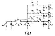
−誘導性磁化モードにおいてエネルギを蓄積するとともに、誘導性減磁モードにおいてエネルギを転送する誘導性回路と、
−少なくとも2つの非反転出力電圧を提供する少なくとも2つの非反転分岐と、
−反転出力電圧を提供する反転分岐と、
を備え、
前記反転分岐及び前記非反転分岐が、前記誘導性回路の出力に並列接続され、前記誘導性回路が、前記反転分岐へ及び前記少なくとも2つの非反転分岐のうちの1つへエネルギを転送し、前記反転電圧及び前記少なくとも2つの非反転分岐のうちの1つの対応する非反転出力電圧が、逆の極性及び略等しい大きさを有する。
Claims (10)
- −誘導性磁化モードにおいてエネルギを蓄積するとともに、誘導性減磁モードにおいてエネルギを転送する誘導性回路と、
−少なくとも2つの非反転出力電圧を提供する少なくとも2つの非反転分岐と、
−反転出力電圧を提供する反転分岐と、
を備え、
前記反転分岐及び前記非反転分岐が、前記誘導性回路の出力に並列接続され、前記誘導性回路が、前記反転分岐へ及び前記少なくとも2つの非反転分岐のうちの1つへエネルギを転送し、前記反転電圧及び前記少なくとも2つの非反転分岐のうちの1つの対応する非反転出力電圧が、逆の極性及び略等しい大きさを有する電圧変換器。 - 前記反転分岐が、前記誘導性減磁モードにおいて転送されるエネルギを蓄積するとともに、前記誘導性磁化モードにおいて前記転送されるエネルギを放出する容量性回路を備える、請求項1に記載の電圧変換器。
- 前記容量性回路が、該容量性回路の入力を介して前記転送されたエネルギを受け取る一方で、該容量性回路の出力が接地電圧に接続され、該容量性回路が、更に、該出力を介してエネルギを放出する一方で、該入力が該接地電圧に接続される、請求項2に記載の電圧変換器。
- 前記誘導性磁化モード及び前記誘導性減磁モードのそれぞれにおいて、該容量性回路の前記入力及び前記出力を前記接地電圧にそれぞれ接続する第1及び第2スイッチ装置を備える、請求項3に記載の電圧変換器。
- 前記電圧変換器が、入力電圧が前記誘導性回路へ供給される電圧降下変換回路を更に備える、請求項1に記載の電圧変換器。
- 前記電圧降下変換回路が、前記誘導性回路に前記入力電圧及び接地電圧を交互に供給する第3及び第4スイッチ装置を備える、請求項5に記載の電圧変換器。
- 前記少なくとも2つの分岐のうちの少なくとも1つが、前記分岐を有効状態にする更なるスイッチ装置を備える、請求項1に記載の電圧変換器。
- 前記電圧変換器が、前記スイッチ装置を制御する制御手段を更に備える、請求項1ないし7の何れか一項に記載の電圧変換器。
- 請求項1ないし8の何れか一項に記載の電圧変換器を備える電源管理ユニット。
- 請求項7に記載の電源ユニットを備える携帯型装置。
Applications Claiming Priority (2)
| Application Number | Priority Date | Filing Date | Title |
|---|---|---|---|
| EP03103887 | 2003-10-21 | ||
| PCT/IB2004/052134 WO2005039033A1 (en) | 2003-10-21 | 2004-10-19 | Voltage converter |
Publications (1)
| Publication Number | Publication Date |
|---|---|
| JP2007509598A true JP2007509598A (ja) | 2007-04-12 |
Family
ID=34443047
Family Applications (1)
| Application Number | Title | Priority Date | Filing Date |
|---|---|---|---|
| JP2006536245A Withdrawn JP2007509598A (ja) | 2003-10-21 | 2004-10-19 | 電圧変換器 |
Country Status (7)
| Country | Link |
|---|---|
| US (1) | US7466114B2 (ja) |
| EP (1) | EP1678817A1 (ja) |
| JP (1) | JP2007509598A (ja) |
| KR (1) | KR20060108617A (ja) |
| CN (1) | CN1871760A (ja) |
| TW (1) | TW200520355A (ja) |
| WO (1) | WO2005039033A1 (ja) |
Cited By (2)
| Publication number | Priority date | Publication date | Assignee | Title |
|---|---|---|---|---|
| JP2008148514A (ja) * | 2006-12-13 | 2008-06-26 | Toppoly Optoelectronics Corp | Dcdcコンバータ |
| JP2010536318A (ja) * | 2007-08-08 | 2010-11-25 | アドバンスト・アナロジック・テクノロジーズ・インコーポレイテッド | 時分割マルチ出力dc/dcコンバータ及び電圧レギュレータ |
Families Citing this family (16)
| Publication number | Priority date | Publication date | Assignee | Title |
|---|---|---|---|---|
| FR2909495B1 (fr) * | 2006-12-05 | 2009-01-16 | Thales Sa | Convertisseur dc dc elevateur de tension |
| US8614569B2 (en) * | 2007-04-24 | 2013-12-24 | St-Ericsson Sa | Method of controlling a switched-mode power supply having a single inductive element and several outputs, and corresponding power supply, in particular for a cellular mobile telephone |
| US7768756B2 (en) | 2007-04-27 | 2010-08-03 | Hewlett-Packard Development Company, L.P. | Leakage current protection circuit |
| TWI411210B (zh) * | 2010-11-23 | 2013-10-01 | Univ Nat Chiao Tung | 具電荷泵控制之單電感多重輸出直流轉換器 |
| EP2466738B1 (en) | 2010-12-20 | 2018-04-04 | ams AG | Voltage converter and method for voltage conversion |
| US8345030B2 (en) | 2011-03-18 | 2013-01-01 | Qualcomm Mems Technologies, Inc. | System and method for providing positive and negative voltages from a single inductor |
| TWI514738B (zh) * | 2011-07-07 | 2015-12-21 | Sitronix Technology Corp | Voltage converter |
| US8786592B2 (en) | 2011-10-13 | 2014-07-22 | Qualcomm Mems Technologies, Inc. | Methods and systems for energy recovery in a display |
| DE102011089648A1 (de) * | 2011-12-22 | 2013-06-27 | Robert Bosch Gmbh | Energiespeichereinrichtung, System mit Energiespeichereinrichtung und Verfahren zum Ansteuern einer Energiespeichereinrichtung |
| US9178422B2 (en) * | 2013-02-21 | 2015-11-03 | Texas Instruments Incorporated | Resonance-based single inductor output-driven DC-DC converter and method |
| US9621021B2 (en) | 2013-06-21 | 2017-04-11 | Microchip Technology Inc. | Auxiliary power supplies in parallel with a switch of a switching regulator |
| US9621037B2 (en) | 2013-10-07 | 2017-04-11 | Microsemi Semiconductor (U.S.) Inc. | Voltage regulator with charge pump for generating second voltage source |
| KR20160001093A (ko) * | 2014-06-26 | 2016-01-06 | 삼성전자주식회사 | 스위칭 레귤레이터를 제어하는 방법 및 전자 장치 |
| US10581241B2 (en) * | 2017-06-22 | 2020-03-03 | Silicon Laboratories Inc. | Clamping inductive flyback voltage to reduce power dissipation |
| DE102021115505A1 (de) * | 2020-06-15 | 2021-12-16 | Maxim Integrated Products, Inc. | Stromgesteuerter Einzelinduktivität-Mehrfachausgang-DC-DC-Wandler mit kontinuierlichem Leitungsmodus und diskontinuierlichem Leitungsmodus |
| WO2025096252A1 (en) * | 2023-10-30 | 2025-05-08 | Qorvo Us, Inc. | Inverting buck-boost hybrid converter topologies |
Family Cites Families (12)
| Publication number | Priority date | Publication date | Assignee | Title |
|---|---|---|---|---|
| US5099144A (en) * | 1988-12-28 | 1992-03-24 | Kabushiki Kaisha Toshiba | Apparatus for optical power transmission and optically powered system |
| US5278688A (en) * | 1990-04-24 | 1994-01-11 | Ortel Corporation | Fault tolerant fiber optic transmission system |
| JP2938958B2 (ja) * | 1990-10-31 | 1999-08-25 | 富士通株式会社 | Dc―dcコンバータ |
| US5617015A (en) * | 1995-06-07 | 1997-04-01 | Linear Technology Corporation | Multiple output regulator with time sequencing |
| US5751139A (en) * | 1997-03-11 | 1998-05-12 | Unitrode Corporation | Multiplexing power converter |
| US6075295A (en) * | 1997-04-14 | 2000-06-13 | Micro Linear Corporation | Single inductor multiple output boost regulator |
| IT1308586B1 (it) * | 1999-01-20 | 2002-01-08 | St Microelectronics Srl | Dispositivo di alimentazione duale con singolo convertitore continua-continua e traslatore capacitivo |
| JP2004503197A (ja) * | 2000-07-06 | 2004-01-29 | コーニンクレッカ フィリップス エレクトロニクス エヌ ヴィ | Pfm/pwmモード用多出力dc/dcコンバータ |
| JP2004518394A (ja) * | 2001-01-17 | 2004-06-17 | コーニンクレッカ フィリップス エレクトロニクス エヌ ヴィ | 制御された多出力dc/dcコンバータ |
| JP2003256052A (ja) * | 2002-02-26 | 2003-09-10 | Sharp Corp | スイッチドキャパシタ型安定化電源回路およびそれを用いる電子機器 |
| JP2003289666A (ja) * | 2002-03-28 | 2003-10-10 | Fujitsu Ltd | スイッチング電源回路 |
| JP2005049830A (ja) * | 2003-07-14 | 2005-02-24 | Fuji Photo Film Co Ltd | 光信号伝送システム |
-
2004
- 2004-10-19 JP JP2006536245A patent/JP2007509598A/ja not_active Withdrawn
- 2004-10-19 WO PCT/IB2004/052134 patent/WO2005039033A1/en not_active Ceased
- 2004-10-19 KR KR1020067007608A patent/KR20060108617A/ko not_active Withdrawn
- 2004-10-19 US US10/576,553 patent/US7466114B2/en not_active Expired - Fee Related
- 2004-10-19 EP EP04770281A patent/EP1678817A1/en not_active Withdrawn
- 2004-10-19 CN CNA2004800310093A patent/CN1871760A/zh active Pending
- 2004-10-20 TW TW093131893A patent/TW200520355A/zh unknown
Cited By (2)
| Publication number | Priority date | Publication date | Assignee | Title |
|---|---|---|---|---|
| JP2008148514A (ja) * | 2006-12-13 | 2008-06-26 | Toppoly Optoelectronics Corp | Dcdcコンバータ |
| JP2010536318A (ja) * | 2007-08-08 | 2010-11-25 | アドバンスト・アナロジック・テクノロジーズ・インコーポレイテッド | 時分割マルチ出力dc/dcコンバータ及び電圧レギュレータ |
Also Published As
| Publication number | Publication date |
|---|---|
| KR20060108617A (ko) | 2006-10-18 |
| CN1871760A (zh) | 2006-11-29 |
| US7466114B2 (en) | 2008-12-16 |
| US20070030617A1 (en) | 2007-02-08 |
| TW200520355A (en) | 2005-06-16 |
| EP1678817A1 (en) | 2006-07-12 |
| WO2005039033A1 (en) | 2005-04-28 |
Similar Documents
| Publication | Publication Date | Title |
|---|---|---|
| JP2007509598A (ja) | 電圧変換器 | |
| TWI455466B (zh) | 具有適應性及無損失的切換過程的切換網路部件以及用於操作此類切換網路部件的方法 | |
| KR102125595B1 (ko) | 컨버터와 다단 배전압 정류회로를 병용한 균등화 기능을 구비한 충방전기 | |
| US10298124B2 (en) | Hybrid DCDC power converter with increased efficiency | |
| KR101367607B1 (ko) | 동기형 dc-dc 컨버터 | |
| US7893662B2 (en) | Method and related device for charging at the same voltage two or more capacitors connected in series | |
| KR100874284B1 (ko) | Dc-dc 변환기, 전자 디바이스, 방법 및 승압 dc-dc변환기 | |
| CN101888734B (zh) | 带升/降压功率因数校正dc-dc转换器的电子镇流器 | |
| CN205092768U (zh) | 能量收集电路 | |
| CN101145699B (zh) | 电源系统和用于控制输出电压的方法 | |
| CN105518969A (zh) | 具有升降压操作的电池充电器 | |
| US20200076305A1 (en) | Electronic converter and method of operating an electronic converter | |
| KR100927649B1 (ko) | 직류 전압 컨버터 | |
| US9660523B2 (en) | System and method for reducing power loss in switched-capacitor power converters | |
| JP2018521622A (ja) | インダクタ電流に基づいてブーストスイッチングレギュレータを制御するための回路および方法 | |
| RU2631265C2 (ru) | Зарядное устройство и способ зарядки | |
| WO2007131779A1 (en) | Voltage generator arrangement and method for voltage conversion | |
| US6396724B1 (en) | Charge-pumped DC bias supply | |
| CN111164870A (zh) | 使用开关调节器和电压限制器的电压倍增器 | |
| KR101022136B1 (ko) | 압전 에너지 수확을 위한 공진형 자려 부스트 컨버터 회로 | |
| EP1691472A1 (en) | Self regulating charge pump | |
| KR20210056696A (ko) | 디커플링 동작을 수행하는 부스트 컨버터 | |
| EP1790065A1 (en) | High efficiency switching power supply | |
| KR20120121818A (ko) | 적응형 전하 펌프 | |
| CN117134479A (zh) | 一种电源转换电路 |
Legal Events
| Date | Code | Title | Description |
|---|---|---|---|
| RD03 | Notification of appointment of power of attorney |
Free format text: JAPANESE INTERMEDIATE CODE: A7423 Effective date: 20070911 |
|
| A621 | Written request for application examination |
Free format text: JAPANESE INTERMEDIATE CODE: A621 Effective date: 20071018 |
|
| A711 | Notification of change in applicant |
Free format text: JAPANESE INTERMEDIATE CODE: A711 Effective date: 20080619 |
|
| A711 | Notification of change in applicant |
Free format text: JAPANESE INTERMEDIATE CODE: A711 Effective date: 20081110 |
|
| A521 | Request for written amendment filed |
Free format text: JAPANESE INTERMEDIATE CODE: A523 Effective date: 20081204 |
|
| A761 | Written withdrawal of application |
Free format text: JAPANESE INTERMEDIATE CODE: A761 Effective date: 20090414 |