JP2007517618A - Artificial spine joint - Google Patents
Artificial spine joint Download PDFInfo
- Publication number
- JP2007517618A JP2007517618A JP2006549472A JP2006549472A JP2007517618A JP 2007517618 A JP2007517618 A JP 2007517618A JP 2006549472 A JP2006549472 A JP 2006549472A JP 2006549472 A JP2006549472 A JP 2006549472A JP 2007517618 A JP2007517618 A JP 2007517618A
- Authority
- JP
- Japan
- Prior art keywords
- component
- joint
- anterior
- posterior
- joint replacement
- Prior art date
- Legal status (The legal status is an assumption and is not a legal conclusion. Google has not performed a legal analysis and makes no representation as to the accuracy of the status listed.)
- Pending
Links
- 210000001503 joint Anatomy 0.000 claims abstract description 69
- 210000000988 bone and bone Anatomy 0.000 claims description 29
- 210000002517 zygapophyseal joint Anatomy 0.000 claims description 22
- 230000007246 mechanism Effects 0.000 claims description 13
- 230000001537 neural effect Effects 0.000 claims description 4
- 238000011882 arthroplasty Methods 0.000 description 34
- 238000013459 approach Methods 0.000 description 24
- 238000000034 method Methods 0.000 description 23
- 239000000463 material Substances 0.000 description 14
- 229910052751 metal Inorganic materials 0.000 description 11
- 239000002184 metal Substances 0.000 description 11
- 230000006870 function Effects 0.000 description 9
- 210000004705 lumbosacral region Anatomy 0.000 description 7
- 239000004696 Poly ether ether ketone Substances 0.000 description 6
- 229920002530 polyetherether ketone Polymers 0.000 description 6
- 239000000919 ceramic Substances 0.000 description 5
- 230000004927 fusion Effects 0.000 description 5
- 238000003780 insertion Methods 0.000 description 5
- 230000037431 insertion Effects 0.000 description 5
- 210000005036 nerve Anatomy 0.000 description 5
- 102100020760 Ferritin heavy chain Human genes 0.000 description 4
- 101001002987 Homo sapiens Ferritin heavy chain Proteins 0.000 description 4
- 238000002513 implantation Methods 0.000 description 4
- 210000003041 ligament Anatomy 0.000 description 4
- 238000012986 modification Methods 0.000 description 4
- 230000004048 modification Effects 0.000 description 4
- 210000003205 muscle Anatomy 0.000 description 4
- 229920000642 polymer Polymers 0.000 description 4
- 238000001356 surgical procedure Methods 0.000 description 4
- 208000007103 Spondylolisthesis Diseases 0.000 description 3
- -1 but not limited to Substances 0.000 description 3
- 230000008878 coupling Effects 0.000 description 3
- 238000010168 coupling process Methods 0.000 description 3
- 238000005859 coupling reaction Methods 0.000 description 3
- 239000004744 fabric Substances 0.000 description 3
- 238000012423 maintenance Methods 0.000 description 3
- 206010039722 scoliosis Diseases 0.000 description 3
- 125000006850 spacer group Chemical group 0.000 description 3
- 239000013589 supplement Substances 0.000 description 3
- 208000024891 symptom Diseases 0.000 description 3
- VTYYLEPIZMXCLO-UHFFFAOYSA-L Calcium carbonate Chemical compound [Ca+2].[O-]C([O-])=O VTYYLEPIZMXCLO-UHFFFAOYSA-L 0.000 description 2
- 206010061246 Intervertebral disc degeneration Diseases 0.000 description 2
- RTAQQCXQSZGOHL-UHFFFAOYSA-N Titanium Chemical compound [Ti] RTAQQCXQSZGOHL-UHFFFAOYSA-N 0.000 description 2
- 102000009618 Transforming Growth Factors Human genes 0.000 description 2
- 108010009583 Transforming Growth Factors Proteins 0.000 description 2
- MCMNRKCIXSYSNV-UHFFFAOYSA-N Zirconium dioxide Chemical compound O=[Zr]=O MCMNRKCIXSYSNV-UHFFFAOYSA-N 0.000 description 2
- 230000004075 alteration Effects 0.000 description 2
- 210000003484 anatomy Anatomy 0.000 description 2
- 230000000712 assembly Effects 0.000 description 2
- 238000000429 assembly Methods 0.000 description 2
- 239000001506 calcium phosphate Substances 0.000 description 2
- 238000000576 coating method Methods 0.000 description 2
- 230000001054 cortical effect Effects 0.000 description 2
- 230000007850 degeneration Effects 0.000 description 2
- 230000003412 degenerative effect Effects 0.000 description 2
- 238000013461 design Methods 0.000 description 2
- 229910003460 diamond Inorganic materials 0.000 description 2
- 239000010432 diamond Substances 0.000 description 2
- 244000013123 dwarf bean Species 0.000 description 2
- 235000021331 green beans Nutrition 0.000 description 2
- 229910052588 hydroxylapatite Inorganic materials 0.000 description 2
- 239000007943 implant Substances 0.000 description 2
- 208000014674 injury Diseases 0.000 description 2
- 230000007659 motor function Effects 0.000 description 2
- 230000002138 osteoinductive effect Effects 0.000 description 2
- 230000001575 pathological effect Effects 0.000 description 2
- XYJRXVWERLGGKC-UHFFFAOYSA-D pentacalcium;hydroxide;triphosphate Chemical compound [OH-].[Ca+2].[Ca+2].[Ca+2].[Ca+2].[Ca+2].[O-]P([O-])([O-])=O.[O-]P([O-])([O-])=O.[O-]P([O-])([O-])=O XYJRXVWERLGGKC-UHFFFAOYSA-D 0.000 description 2
- 239000004033 plastic Substances 0.000 description 2
- 229920003023 plastic Polymers 0.000 description 2
- 229920001652 poly(etherketoneketone) Polymers 0.000 description 2
- 229920003229 poly(methyl methacrylate) Polymers 0.000 description 2
- 239000004926 polymethyl methacrylate Substances 0.000 description 2
- 102000004169 proteins and genes Human genes 0.000 description 2
- 108090000623 proteins and genes Proteins 0.000 description 2
- 210000000954 sacrococcygeal region Anatomy 0.000 description 2
- 210000001519 tissue Anatomy 0.000 description 2
- 239000010936 titanium Substances 0.000 description 2
- 229910052719 titanium Inorganic materials 0.000 description 2
- 238000013519 translation Methods 0.000 description 2
- 230000008733 trauma Effects 0.000 description 2
- QORWJWZARLRLPR-UHFFFAOYSA-H tricalcium bis(phosphate) Chemical compound [Ca+2].[Ca+2].[Ca+2].[O-]P([O-])([O-])=O.[O-]P([O-])([O-])=O QORWJWZARLRLPR-UHFFFAOYSA-H 0.000 description 2
- 229940078499 tricalcium phosphate Drugs 0.000 description 2
- 229910000391 tricalcium phosphate Inorganic materials 0.000 description 2
- 235000019731 tricalcium phosphate Nutrition 0.000 description 2
- 102100024506 Bone morphogenetic protein 2 Human genes 0.000 description 1
- 102100022544 Bone morphogenetic protein 7 Human genes 0.000 description 1
- OYPRJOBELJOOCE-UHFFFAOYSA-N Calcium Chemical compound [Ca] OYPRJOBELJOOCE-UHFFFAOYSA-N 0.000 description 1
- OKTJSMMVPCPJKN-UHFFFAOYSA-N Carbon Chemical compound [C] OKTJSMMVPCPJKN-UHFFFAOYSA-N 0.000 description 1
- 229920000049 Carbon (fiber) Polymers 0.000 description 1
- 229910000684 Cobalt-chrome Inorganic materials 0.000 description 1
- 206010073681 Epidural haemorrhage Diseases 0.000 description 1
- 206010016059 Facial pain Diseases 0.000 description 1
- 239000004705 High-molecular-weight polyethylene Substances 0.000 description 1
- 101000762366 Homo sapiens Bone morphogenetic protein 2 Proteins 0.000 description 1
- 101000899361 Homo sapiens Bone morphogenetic protein 7 Proteins 0.000 description 1
- 229910019142 PO4 Inorganic materials 0.000 description 1
- 208000002193 Pain Diseases 0.000 description 1
- 239000004697 Polyetherimide Substances 0.000 description 1
- 239000004642 Polyimide Substances 0.000 description 1
- 229910001069 Ti alloy Inorganic materials 0.000 description 1
- 229920010741 Ultra High Molecular Weight Polyethylene (UHMWPE) Polymers 0.000 description 1
- 239000004699 Ultra-high molecular weight polyethylene Substances 0.000 description 1
- HZEWFHLRYVTOIW-UHFFFAOYSA-N [Ti].[Ni] Chemical compound [Ti].[Ni] HZEWFHLRYVTOIW-UHFFFAOYSA-N 0.000 description 1
- 239000000853 adhesive Substances 0.000 description 1
- 230000001070 adhesive effect Effects 0.000 description 1
- 229910045601 alloy Inorganic materials 0.000 description 1
- 239000000956 alloy Substances 0.000 description 1
- PNEYBMLMFCGWSK-UHFFFAOYSA-N aluminium oxide Inorganic materials [O-2].[O-2].[O-2].[Al+3].[Al+3] PNEYBMLMFCGWSK-UHFFFAOYSA-N 0.000 description 1
- 208000037873 arthrodesis Diseases 0.000 description 1
- 239000011324 bead Substances 0.000 description 1
- 239000000560 biocompatible material Substances 0.000 description 1
- 229910052791 calcium Inorganic materials 0.000 description 1
- 239000011575 calcium Substances 0.000 description 1
- 229910000019 calcium carbonate Inorganic materials 0.000 description 1
- 229910052799 carbon Inorganic materials 0.000 description 1
- 239000004917 carbon fiber Substances 0.000 description 1
- 210000000845 cartilage Anatomy 0.000 description 1
- 239000004568 cement Substances 0.000 description 1
- 229910010293 ceramic material Inorganic materials 0.000 description 1
- 238000003486 chemical etching Methods 0.000 description 1
- 239000000788 chromium alloy Substances 0.000 description 1
- 239000011248 coating agent Substances 0.000 description 1
- 239000010952 cobalt-chrome Substances 0.000 description 1
- 230000000295 complement effect Effects 0.000 description 1
- 238000010276 construction Methods 0.000 description 1
- 238000012937 correction Methods 0.000 description 1
- 230000005786 degenerative changes Effects 0.000 description 1
- 238000010586 diagram Methods 0.000 description 1
- 238000006073 displacement reaction Methods 0.000 description 1
- 210000001951 dura mater Anatomy 0.000 description 1
- 230000000694 effects Effects 0.000 description 1
- RTZKZFJDLAIYFH-UHFFFAOYSA-N ether Substances CCOCC RTZKZFJDLAIYFH-UHFFFAOYSA-N 0.000 description 1
- 230000005484 gravity Effects 0.000 description 1
- 238000011065 in-situ storage Methods 0.000 description 1
- 230000003993 interaction Effects 0.000 description 1
- 230000008407 joint function Effects 0.000 description 1
- 229910001092 metal group alloy Inorganic materials 0.000 description 1
- 150000002739 metals Chemical class 0.000 description 1
- 239000003607 modifier Substances 0.000 description 1
- 230000000921 morphogenic effect Effects 0.000 description 1
- 229910001000 nickel titanium Inorganic materials 0.000 description 1
- TWNQGVIAIRXVLR-UHFFFAOYSA-N oxo(oxoalumanyloxy)alumane Chemical compound O=[Al]O[Al]=O TWNQGVIAIRXVLR-UHFFFAOYSA-N 0.000 description 1
- RVTZCBVAJQQJTK-UHFFFAOYSA-N oxygen(2-);zirconium(4+) Chemical compound [O-2].[O-2].[Zr+4] RVTZCBVAJQQJTK-UHFFFAOYSA-N 0.000 description 1
- NBIIXXVUZAFLBC-UHFFFAOYSA-K phosphate Chemical compound [O-]P([O-])([O-])=O NBIIXXVUZAFLBC-UHFFFAOYSA-K 0.000 description 1
- 239000010452 phosphate Substances 0.000 description 1
- 229920002492 poly(sulfone) Polymers 0.000 description 1
- 229920001601 polyetherimide Polymers 0.000 description 1
- 229920001721 polyimide Polymers 0.000 description 1
- 230000008569 process Effects 0.000 description 1
- 239000002296 pyrolytic carbon Substances 0.000 description 1
- 238000007493 shaping process Methods 0.000 description 1
- 210000004872 soft tissue Anatomy 0.000 description 1
- 210000003594 spinal ganglia Anatomy 0.000 description 1
- 208000005198 spinal stenosis Diseases 0.000 description 1
- 238000005507 spraying Methods 0.000 description 1
- 229910001220 stainless steel Inorganic materials 0.000 description 1
- 239000010935 stainless steel Substances 0.000 description 1
- 229910001256 stainless steel alloy Inorganic materials 0.000 description 1
- 239000000126 substance Substances 0.000 description 1
- 238000006467 substitution reaction Methods 0.000 description 1
- 229920002994 synthetic fiber Polymers 0.000 description 1
- 239000012209 synthetic fiber Substances 0.000 description 1
- 210000000115 thoracic cavity Anatomy 0.000 description 1
- 230000007704 transition Effects 0.000 description 1
- 229920000785 ultra high molecular weight polyethylene Polymers 0.000 description 1
- 239000000602 vitallium Substances 0.000 description 1
- 229910001928 zirconium oxide Inorganic materials 0.000 description 1
Images

Classifications
-
- A—HUMAN NECESSITIES
- A61—MEDICAL OR VETERINARY SCIENCE; HYGIENE
- A61F—FILTERS IMPLANTABLE INTO BLOOD VESSELS; PROSTHESES; DEVICES PROVIDING PATENCY TO, OR PREVENTING COLLAPSING OF, TUBULAR STRUCTURES OF THE BODY, e.g. STENTS; ORTHOPAEDIC, NURSING OR CONTRACEPTIVE DEVICES; FOMENTATION; TREATMENT OR PROTECTION OF EYES OR EARS; BANDAGES, DRESSINGS OR ABSORBENT PADS; FIRST-AID KITS
- A61F2/00—Filters implantable into blood vessels; Prostheses, i.e. artificial substitutes or replacements for parts of the body; Appliances for connecting them with the body; Devices providing patency to, or preventing collapsing of, tubular structures of the body, e.g. stents
- A61F2/02—Prostheses implantable into the body
- A61F2/30—Joints
- A61F2/44—Joints for the spine, e.g. vertebrae, spinal discs
- A61F2/442—Intervertebral or spinal discs, e.g. resilient
- A61F2/4425—Intervertebral or spinal discs, e.g. resilient made of articulated components
-
- A—HUMAN NECESSITIES
- A61—MEDICAL OR VETERINARY SCIENCE; HYGIENE
- A61B—DIAGNOSIS; SURGERY; IDENTIFICATION
- A61B17/00—Surgical instruments, devices or methods
- A61B17/56—Surgical instruments or methods for treatment of bones or joints; Devices specially adapted therefor
- A61B17/58—Surgical instruments or methods for treatment of bones or joints; Devices specially adapted therefor for osteosynthesis, e.g. bone plates, screws or setting implements
- A61B17/68—Internal fixation devices, including fasteners and spinal fixators, even if a part thereof projects from the skin
- A61B17/84—Fasteners therefor or fasteners being internal fixation devices
- A61B17/86—Pins or screws or threaded wires; nuts therefor
-
- A—HUMAN NECESSITIES
- A61—MEDICAL OR VETERINARY SCIENCE; HYGIENE
- A61F—FILTERS IMPLANTABLE INTO BLOOD VESSELS; PROSTHESES; DEVICES PROVIDING PATENCY TO, OR PREVENTING COLLAPSING OF, TUBULAR STRUCTURES OF THE BODY, e.g. STENTS; ORTHOPAEDIC, NURSING OR CONTRACEPTIVE DEVICES; FOMENTATION; TREATMENT OR PROTECTION OF EYES OR EARS; BANDAGES, DRESSINGS OR ABSORBENT PADS; FIRST-AID KITS
- A61F2/00—Filters implantable into blood vessels; Prostheses, i.e. artificial substitutes or replacements for parts of the body; Appliances for connecting them with the body; Devices providing patency to, or preventing collapsing of, tubular structures of the body, e.g. stents
- A61F2/02—Prostheses implantable into the body
- A61F2/08—Muscles; Tendons; Ligaments
-
- A—HUMAN NECESSITIES
- A61—MEDICAL OR VETERINARY SCIENCE; HYGIENE
- A61F—FILTERS IMPLANTABLE INTO BLOOD VESSELS; PROSTHESES; DEVICES PROVIDING PATENCY TO, OR PREVENTING COLLAPSING OF, TUBULAR STRUCTURES OF THE BODY, e.g. STENTS; ORTHOPAEDIC, NURSING OR CONTRACEPTIVE DEVICES; FOMENTATION; TREATMENT OR PROTECTION OF EYES OR EARS; BANDAGES, DRESSINGS OR ABSORBENT PADS; FIRST-AID KITS
- A61F2/00—Filters implantable into blood vessels; Prostheses, i.e. artificial substitutes or replacements for parts of the body; Appliances for connecting them with the body; Devices providing patency to, or preventing collapsing of, tubular structures of the body, e.g. stents
- A61F2/02—Prostheses implantable into the body
- A61F2/30—Joints
- A61F2/3094—Designing or manufacturing processes
- A61F2/30965—Reinforcing the prosthesis by embedding particles or fibres during moulding or dipping
-
- A—HUMAN NECESSITIES
- A61—MEDICAL OR VETERINARY SCIENCE; HYGIENE
- A61F—FILTERS IMPLANTABLE INTO BLOOD VESSELS; PROSTHESES; DEVICES PROVIDING PATENCY TO, OR PREVENTING COLLAPSING OF, TUBULAR STRUCTURES OF THE BODY, e.g. STENTS; ORTHOPAEDIC, NURSING OR CONTRACEPTIVE DEVICES; FOMENTATION; TREATMENT OR PROTECTION OF EYES OR EARS; BANDAGES, DRESSINGS OR ABSORBENT PADS; FIRST-AID KITS
- A61F2/00—Filters implantable into blood vessels; Prostheses, i.e. artificial substitutes or replacements for parts of the body; Appliances for connecting them with the body; Devices providing patency to, or preventing collapsing of, tubular structures of the body, e.g. stents
- A61F2/02—Prostheses implantable into the body
- A61F2/30—Joints
- A61F2/44—Joints for the spine, e.g. vertebrae, spinal discs
- A61F2/4405—Joints for the spine, e.g. vertebrae, spinal discs for apophyseal or facet joints, i.e. between adjacent spinous or transverse processes
-
- A—HUMAN NECESSITIES
- A61—MEDICAL OR VETERINARY SCIENCE; HYGIENE
- A61F—FILTERS IMPLANTABLE INTO BLOOD VESSELS; PROSTHESES; DEVICES PROVIDING PATENCY TO, OR PREVENTING COLLAPSING OF, TUBULAR STRUCTURES OF THE BODY, e.g. STENTS; ORTHOPAEDIC, NURSING OR CONTRACEPTIVE DEVICES; FOMENTATION; TREATMENT OR PROTECTION OF EYES OR EARS; BANDAGES, DRESSINGS OR ABSORBENT PADS; FIRST-AID KITS
- A61F2/00—Filters implantable into blood vessels; Prostheses, i.e. artificial substitutes or replacements for parts of the body; Appliances for connecting them with the body; Devices providing patency to, or preventing collapsing of, tubular structures of the body, e.g. stents
- A61F2/02—Prostheses implantable into the body
- A61F2/28—Bones
- A61F2002/2817—Bone stimulation by chemical reactions or by osteogenic or biological products for enhancing ossification, e.g. by bone morphogenetic or morphogenic proteins [BMP] or by transforming growth factors [TGF]
-
- A—HUMAN NECESSITIES
- A61—MEDICAL OR VETERINARY SCIENCE; HYGIENE
- A61F—FILTERS IMPLANTABLE INTO BLOOD VESSELS; PROSTHESES; DEVICES PROVIDING PATENCY TO, OR PREVENTING COLLAPSING OF, TUBULAR STRUCTURES OF THE BODY, e.g. STENTS; ORTHOPAEDIC, NURSING OR CONTRACEPTIVE DEVICES; FOMENTATION; TREATMENT OR PROTECTION OF EYES OR EARS; BANDAGES, DRESSINGS OR ABSORBENT PADS; FIRST-AID KITS
- A61F2/00—Filters implantable into blood vessels; Prostheses, i.e. artificial substitutes or replacements for parts of the body; Appliances for connecting them with the body; Devices providing patency to, or preventing collapsing of, tubular structures of the body, e.g. stents
- A61F2/02—Prostheses implantable into the body
- A61F2/30—Joints
- A61F2002/30001—Additional features of subject-matter classified in A61F2/28, A61F2/30 and subgroups thereof
- A61F2002/30316—The prosthesis having different structural features at different locations within the same prosthesis; Connections between prosthetic parts; Special structural features of bone or joint prostheses not otherwise provided for
- A61F2002/30329—Connections or couplings between prosthetic parts, e.g. between modular parts; Connecting elements
- A61F2002/30331—Connections or couplings between prosthetic parts, e.g. between modular parts; Connecting elements made by longitudinally pushing a protrusion into a complementarily-shaped recess, e.g. held by friction fit
-
- A—HUMAN NECESSITIES
- A61—MEDICAL OR VETERINARY SCIENCE; HYGIENE
- A61F—FILTERS IMPLANTABLE INTO BLOOD VESSELS; PROSTHESES; DEVICES PROVIDING PATENCY TO, OR PREVENTING COLLAPSING OF, TUBULAR STRUCTURES OF THE BODY, e.g. STENTS; ORTHOPAEDIC, NURSING OR CONTRACEPTIVE DEVICES; FOMENTATION; TREATMENT OR PROTECTION OF EYES OR EARS; BANDAGES, DRESSINGS OR ABSORBENT PADS; FIRST-AID KITS
- A61F2/00—Filters implantable into blood vessels; Prostheses, i.e. artificial substitutes or replacements for parts of the body; Appliances for connecting them with the body; Devices providing patency to, or preventing collapsing of, tubular structures of the body, e.g. stents
- A61F2/02—Prostheses implantable into the body
- A61F2/30—Joints
- A61F2002/30001—Additional features of subject-matter classified in A61F2/28, A61F2/30 and subgroups thereof
- A61F2002/30316—The prosthesis having different structural features at different locations within the same prosthesis; Connections between prosthetic parts; Special structural features of bone or joint prostheses not otherwise provided for
- A61F2002/30329—Connections or couplings between prosthetic parts, e.g. between modular parts; Connecting elements
- A61F2002/30383—Connections or couplings between prosthetic parts, e.g. between modular parts; Connecting elements made by laterally inserting a protrusion, e.g. a rib into a complementarily-shaped groove
-
- A—HUMAN NECESSITIES
- A61—MEDICAL OR VETERINARY SCIENCE; HYGIENE
- A61F—FILTERS IMPLANTABLE INTO BLOOD VESSELS; PROSTHESES; DEVICES PROVIDING PATENCY TO, OR PREVENTING COLLAPSING OF, TUBULAR STRUCTURES OF THE BODY, e.g. STENTS; ORTHOPAEDIC, NURSING OR CONTRACEPTIVE DEVICES; FOMENTATION; TREATMENT OR PROTECTION OF EYES OR EARS; BANDAGES, DRESSINGS OR ABSORBENT PADS; FIRST-AID KITS
- A61F2/00—Filters implantable into blood vessels; Prostheses, i.e. artificial substitutes or replacements for parts of the body; Appliances for connecting them with the body; Devices providing patency to, or preventing collapsing of, tubular structures of the body, e.g. stents
- A61F2/02—Prostheses implantable into the body
- A61F2/30—Joints
- A61F2002/30001—Additional features of subject-matter classified in A61F2/28, A61F2/30 and subgroups thereof
- A61F2002/30316—The prosthesis having different structural features at different locations within the same prosthesis; Connections between prosthetic parts; Special structural features of bone or joint prostheses not otherwise provided for
- A61F2002/30329—Connections or couplings between prosthetic parts, e.g. between modular parts; Connecting elements
- A61F2002/30433—Connections or couplings between prosthetic parts, e.g. between modular parts; Connecting elements using additional screws, bolts, dowels, rivets or washers e.g. connecting screws
-
- A—HUMAN NECESSITIES
- A61—MEDICAL OR VETERINARY SCIENCE; HYGIENE
- A61F—FILTERS IMPLANTABLE INTO BLOOD VESSELS; PROSTHESES; DEVICES PROVIDING PATENCY TO, OR PREVENTING COLLAPSING OF, TUBULAR STRUCTURES OF THE BODY, e.g. STENTS; ORTHOPAEDIC, NURSING OR CONTRACEPTIVE DEVICES; FOMENTATION; TREATMENT OR PROTECTION OF EYES OR EARS; BANDAGES, DRESSINGS OR ABSORBENT PADS; FIRST-AID KITS
- A61F2/00—Filters implantable into blood vessels; Prostheses, i.e. artificial substitutes or replacements for parts of the body; Appliances for connecting them with the body; Devices providing patency to, or preventing collapsing of, tubular structures of the body, e.g. stents
- A61F2/02—Prostheses implantable into the body
- A61F2/30—Joints
- A61F2002/30001—Additional features of subject-matter classified in A61F2/28, A61F2/30 and subgroups thereof
- A61F2002/30316—The prosthesis having different structural features at different locations within the same prosthesis; Connections between prosthetic parts; Special structural features of bone or joint prostheses not otherwise provided for
- A61F2002/30329—Connections or couplings between prosthetic parts, e.g. between modular parts; Connecting elements
- A61F2002/30462—Connections or couplings between prosthetic parts, e.g. between modular parts; Connecting elements retained or tied with a rope, string, thread, wire or cable
-
- A—HUMAN NECESSITIES
- A61—MEDICAL OR VETERINARY SCIENCE; HYGIENE
- A61F—FILTERS IMPLANTABLE INTO BLOOD VESSELS; PROSTHESES; DEVICES PROVIDING PATENCY TO, OR PREVENTING COLLAPSING OF, TUBULAR STRUCTURES OF THE BODY, e.g. STENTS; ORTHOPAEDIC, NURSING OR CONTRACEPTIVE DEVICES; FOMENTATION; TREATMENT OR PROTECTION OF EYES OR EARS; BANDAGES, DRESSINGS OR ABSORBENT PADS; FIRST-AID KITS
- A61F2/00—Filters implantable into blood vessels; Prostheses, i.e. artificial substitutes or replacements for parts of the body; Appliances for connecting them with the body; Devices providing patency to, or preventing collapsing of, tubular structures of the body, e.g. stents
- A61F2/02—Prostheses implantable into the body
- A61F2/30—Joints
- A61F2002/30001—Additional features of subject-matter classified in A61F2/28, A61F2/30 and subgroups thereof
- A61F2002/30316—The prosthesis having different structural features at different locations within the same prosthesis; Connections between prosthetic parts; Special structural features of bone or joint prostheses not otherwise provided for
- A61F2002/30535—Special structural features of bone or joint prostheses not otherwise provided for
- A61F2002/30576—Special structural features of bone or joint prostheses not otherwise provided for with extending fixation tabs
- A61F2002/30578—Special structural features of bone or joint prostheses not otherwise provided for with extending fixation tabs having apertures, e.g. for receiving fixation screws
-
- A—HUMAN NECESSITIES
- A61—MEDICAL OR VETERINARY SCIENCE; HYGIENE
- A61F—FILTERS IMPLANTABLE INTO BLOOD VESSELS; PROSTHESES; DEVICES PROVIDING PATENCY TO, OR PREVENTING COLLAPSING OF, TUBULAR STRUCTURES OF THE BODY, e.g. STENTS; ORTHOPAEDIC, NURSING OR CONTRACEPTIVE DEVICES; FOMENTATION; TREATMENT OR PROTECTION OF EYES OR EARS; BANDAGES, DRESSINGS OR ABSORBENT PADS; FIRST-AID KITS
- A61F2/00—Filters implantable into blood vessels; Prostheses, i.e. artificial substitutes or replacements for parts of the body; Appliances for connecting them with the body; Devices providing patency to, or preventing collapsing of, tubular structures of the body, e.g. stents
- A61F2/02—Prostheses implantable into the body
- A61F2/30—Joints
- A61F2002/30001—Additional features of subject-matter classified in A61F2/28, A61F2/30 and subgroups thereof
- A61F2002/30316—The prosthesis having different structural features at different locations within the same prosthesis; Connections between prosthetic parts; Special structural features of bone or joint prostheses not otherwise provided for
- A61F2002/30535—Special structural features of bone or joint prostheses not otherwise provided for
- A61F2002/30604—Special structural features of bone or joint prostheses not otherwise provided for modular
- A61F2002/30616—Sets comprising a plurality of prosthetic parts of different sizes or orientations
-
- A—HUMAN NECESSITIES
- A61—MEDICAL OR VETERINARY SCIENCE; HYGIENE
- A61F—FILTERS IMPLANTABLE INTO BLOOD VESSELS; PROSTHESES; DEVICES PROVIDING PATENCY TO, OR PREVENTING COLLAPSING OF, TUBULAR STRUCTURES OF THE BODY, e.g. STENTS; ORTHOPAEDIC, NURSING OR CONTRACEPTIVE DEVICES; FOMENTATION; TREATMENT OR PROTECTION OF EYES OR EARS; BANDAGES, DRESSINGS OR ABSORBENT PADS; FIRST-AID KITS
- A61F2/00—Filters implantable into blood vessels; Prostheses, i.e. artificial substitutes or replacements for parts of the body; Appliances for connecting them with the body; Devices providing patency to, or preventing collapsing of, tubular structures of the body, e.g. stents
- A61F2/02—Prostheses implantable into the body
- A61F2/30—Joints
- A61F2002/30001—Additional features of subject-matter classified in A61F2/28, A61F2/30 and subgroups thereof
- A61F2002/30621—Features concerning the anatomical functioning or articulation of the prosthetic joint
- A61F2002/30649—Ball-and-socket joints
- A61F2002/30654—Details of the concave socket
-
- A—HUMAN NECESSITIES
- A61—MEDICAL OR VETERINARY SCIENCE; HYGIENE
- A61F—FILTERS IMPLANTABLE INTO BLOOD VESSELS; PROSTHESES; DEVICES PROVIDING PATENCY TO, OR PREVENTING COLLAPSING OF, TUBULAR STRUCTURES OF THE BODY, e.g. STENTS; ORTHOPAEDIC, NURSING OR CONTRACEPTIVE DEVICES; FOMENTATION; TREATMENT OR PROTECTION OF EYES OR EARS; BANDAGES, DRESSINGS OR ABSORBENT PADS; FIRST-AID KITS
- A61F2/00—Filters implantable into blood vessels; Prostheses, i.e. artificial substitutes or replacements for parts of the body; Appliances for connecting them with the body; Devices providing patency to, or preventing collapsing of, tubular structures of the body, e.g. stents
- A61F2/02—Prostheses implantable into the body
- A61F2/30—Joints
- A61F2002/30001—Additional features of subject-matter classified in A61F2/28, A61F2/30 and subgroups thereof
- A61F2002/30621—Features concerning the anatomical functioning or articulation of the prosthetic joint
- A61F2002/30649—Ball-and-socket joints
- A61F2002/30662—Ball-and-socket joints with rotation-limiting means
-
- A—HUMAN NECESSITIES
- A61—MEDICAL OR VETERINARY SCIENCE; HYGIENE
- A61F—FILTERS IMPLANTABLE INTO BLOOD VESSELS; PROSTHESES; DEVICES PROVIDING PATENCY TO, OR PREVENTING COLLAPSING OF, TUBULAR STRUCTURES OF THE BODY, e.g. STENTS; ORTHOPAEDIC, NURSING OR CONTRACEPTIVE DEVICES; FOMENTATION; TREATMENT OR PROTECTION OF EYES OR EARS; BANDAGES, DRESSINGS OR ABSORBENT PADS; FIRST-AID KITS
- A61F2/00—Filters implantable into blood vessels; Prostheses, i.e. artificial substitutes or replacements for parts of the body; Appliances for connecting them with the body; Devices providing patency to, or preventing collapsing of, tubular structures of the body, e.g. stents
- A61F2/02—Prostheses implantable into the body
- A61F2/30—Joints
- A61F2002/30001—Additional features of subject-matter classified in A61F2/28, A61F2/30 and subgroups thereof
- A61F2002/30621—Features concerning the anatomical functioning or articulation of the prosthetic joint
- A61F2002/30649—Ball-and-socket joints
- A61F2002/30665—Dual arrangement of two adjacent ball-and-socket joints
-
- A—HUMAN NECESSITIES
- A61—MEDICAL OR VETERINARY SCIENCE; HYGIENE
- A61F—FILTERS IMPLANTABLE INTO BLOOD VESSELS; PROSTHESES; DEVICES PROVIDING PATENCY TO, OR PREVENTING COLLAPSING OF, TUBULAR STRUCTURES OF THE BODY, e.g. STENTS; ORTHOPAEDIC, NURSING OR CONTRACEPTIVE DEVICES; FOMENTATION; TREATMENT OR PROTECTION OF EYES OR EARS; BANDAGES, DRESSINGS OR ABSORBENT PADS; FIRST-AID KITS
- A61F2/00—Filters implantable into blood vessels; Prostheses, i.e. artificial substitutes or replacements for parts of the body; Appliances for connecting them with the body; Devices providing patency to, or preventing collapsing of, tubular structures of the body, e.g. stents
- A61F2/02—Prostheses implantable into the body
- A61F2/30—Joints
- A61F2002/30001—Additional features of subject-matter classified in A61F2/28, A61F2/30 and subgroups thereof
- A61F2002/30667—Features concerning an interaction with the environment or a particular use of the prosthesis
- A61F2002/30682—Means for preventing migration of particles released by the joint, e.g. wear debris or cement particles
- A61F2002/30685—Means for reducing or preventing the generation of wear particulates
-
- A—HUMAN NECESSITIES
- A61—MEDICAL OR VETERINARY SCIENCE; HYGIENE
- A61F—FILTERS IMPLANTABLE INTO BLOOD VESSELS; PROSTHESES; DEVICES PROVIDING PATENCY TO, OR PREVENTING COLLAPSING OF, TUBULAR STRUCTURES OF THE BODY, e.g. STENTS; ORTHOPAEDIC, NURSING OR CONTRACEPTIVE DEVICES; FOMENTATION; TREATMENT OR PROTECTION OF EYES OR EARS; BANDAGES, DRESSINGS OR ABSORBENT PADS; FIRST-AID KITS
- A61F2/00—Filters implantable into blood vessels; Prostheses, i.e. artificial substitutes or replacements for parts of the body; Appliances for connecting them with the body; Devices providing patency to, or preventing collapsing of, tubular structures of the body, e.g. stents
- A61F2/02—Prostheses implantable into the body
- A61F2/30—Joints
- A61F2002/30001—Additional features of subject-matter classified in A61F2/28, A61F2/30 and subgroups thereof
- A61F2002/30667—Features concerning an interaction with the environment or a particular use of the prosthesis
- A61F2002/3069—Revision endoprostheses
-
- A—HUMAN NECESSITIES
- A61—MEDICAL OR VETERINARY SCIENCE; HYGIENE
- A61F—FILTERS IMPLANTABLE INTO BLOOD VESSELS; PROSTHESES; DEVICES PROVIDING PATENCY TO, OR PREVENTING COLLAPSING OF, TUBULAR STRUCTURES OF THE BODY, e.g. STENTS; ORTHOPAEDIC, NURSING OR CONTRACEPTIVE DEVICES; FOMENTATION; TREATMENT OR PROTECTION OF EYES OR EARS; BANDAGES, DRESSINGS OR ABSORBENT PADS; FIRST-AID KITS
- A61F2/00—Filters implantable into blood vessels; Prostheses, i.e. artificial substitutes or replacements for parts of the body; Appliances for connecting them with the body; Devices providing patency to, or preventing collapsing of, tubular structures of the body, e.g. stents
- A61F2/02—Prostheses implantable into the body
- A61F2/30—Joints
- A61F2/30767—Special external or bone-contacting surface, e.g. coating for improving bone ingrowth
- A61F2002/30769—Special external or bone-contacting surface, e.g. coating for improving bone ingrowth madreporic
-
- A—HUMAN NECESSITIES
- A61—MEDICAL OR VETERINARY SCIENCE; HYGIENE
- A61F—FILTERS IMPLANTABLE INTO BLOOD VESSELS; PROSTHESES; DEVICES PROVIDING PATENCY TO, OR PREVENTING COLLAPSING OF, TUBULAR STRUCTURES OF THE BODY, e.g. STENTS; ORTHOPAEDIC, NURSING OR CONTRACEPTIVE DEVICES; FOMENTATION; TREATMENT OR PROTECTION OF EYES OR EARS; BANDAGES, DRESSINGS OR ABSORBENT PADS; FIRST-AID KITS
- A61F2/00—Filters implantable into blood vessels; Prostheses, i.e. artificial substitutes or replacements for parts of the body; Appliances for connecting them with the body; Devices providing patency to, or preventing collapsing of, tubular structures of the body, e.g. stents
- A61F2/02—Prostheses implantable into the body
- A61F2/30—Joints
- A61F2/30767—Special external or bone-contacting surface, e.g. coating for improving bone ingrowth
- A61F2/30771—Special external or bone-contacting surface, e.g. coating for improving bone ingrowth applied in original prostheses, e.g. holes or grooves
- A61F2002/3082—Grooves
-
- A—HUMAN NECESSITIES
- A61—MEDICAL OR VETERINARY SCIENCE; HYGIENE
- A61F—FILTERS IMPLANTABLE INTO BLOOD VESSELS; PROSTHESES; DEVICES PROVIDING PATENCY TO, OR PREVENTING COLLAPSING OF, TUBULAR STRUCTURES OF THE BODY, e.g. STENTS; ORTHOPAEDIC, NURSING OR CONTRACEPTIVE DEVICES; FOMENTATION; TREATMENT OR PROTECTION OF EYES OR EARS; BANDAGES, DRESSINGS OR ABSORBENT PADS; FIRST-AID KITS
- A61F2/00—Filters implantable into blood vessels; Prostheses, i.e. artificial substitutes or replacements for parts of the body; Appliances for connecting them with the body; Devices providing patency to, or preventing collapsing of, tubular structures of the body, e.g. stents
- A61F2/02—Prostheses implantable into the body
- A61F2/30—Joints
- A61F2/30767—Special external or bone-contacting surface, e.g. coating for improving bone ingrowth
- A61F2/30771—Special external or bone-contacting surface, e.g. coating for improving bone ingrowth applied in original prostheses, e.g. holes or grooves
- A61F2002/30841—Sharp anchoring protrusions for impaction into the bone, e.g. sharp pins, spikes
-
- A—HUMAN NECESSITIES
- A61—MEDICAL OR VETERINARY SCIENCE; HYGIENE
- A61F—FILTERS IMPLANTABLE INTO BLOOD VESSELS; PROSTHESES; DEVICES PROVIDING PATENCY TO, OR PREVENTING COLLAPSING OF, TUBULAR STRUCTURES OF THE BODY, e.g. STENTS; ORTHOPAEDIC, NURSING OR CONTRACEPTIVE DEVICES; FOMENTATION; TREATMENT OR PROTECTION OF EYES OR EARS; BANDAGES, DRESSINGS OR ABSORBENT PADS; FIRST-AID KITS
- A61F2/00—Filters implantable into blood vessels; Prostheses, i.e. artificial substitutes or replacements for parts of the body; Appliances for connecting them with the body; Devices providing patency to, or preventing collapsing of, tubular structures of the body, e.g. stents
- A61F2/02—Prostheses implantable into the body
- A61F2/30—Joints
- A61F2/30767—Special external or bone-contacting surface, e.g. coating for improving bone ingrowth
- A61F2/30771—Special external or bone-contacting surface, e.g. coating for improving bone ingrowth applied in original prostheses, e.g. holes or grooves
- A61F2002/30878—Special external or bone-contacting surface, e.g. coating for improving bone ingrowth applied in original prostheses, e.g. holes or grooves with non-sharp protrusions, for instance contacting the bone for anchoring, e.g. keels, pegs, pins, posts, shanks, stems, struts
- A61F2002/30884—Fins or wings, e.g. longitudinal wings for preventing rotation within the bone cavity
-
- A—HUMAN NECESSITIES
- A61—MEDICAL OR VETERINARY SCIENCE; HYGIENE
- A61F—FILTERS IMPLANTABLE INTO BLOOD VESSELS; PROSTHESES; DEVICES PROVIDING PATENCY TO, OR PREVENTING COLLAPSING OF, TUBULAR STRUCTURES OF THE BODY, e.g. STENTS; ORTHOPAEDIC, NURSING OR CONTRACEPTIVE DEVICES; FOMENTATION; TREATMENT OR PROTECTION OF EYES OR EARS; BANDAGES, DRESSINGS OR ABSORBENT PADS; FIRST-AID KITS
- A61F2/00—Filters implantable into blood vessels; Prostheses, i.e. artificial substitutes or replacements for parts of the body; Appliances for connecting them with the body; Devices providing patency to, or preventing collapsing of, tubular structures of the body, e.g. stents
- A61F2/02—Prostheses implantable into the body
- A61F2/30—Joints
- A61F2/30767—Special external or bone-contacting surface, e.g. coating for improving bone ingrowth
- A61F2002/30906—Special external or bone-contacting surface, e.g. coating for improving bone ingrowth shot- sand- or grit-blasted
-
- A—HUMAN NECESSITIES
- A61—MEDICAL OR VETERINARY SCIENCE; HYGIENE
- A61F—FILTERS IMPLANTABLE INTO BLOOD VESSELS; PROSTHESES; DEVICES PROVIDING PATENCY TO, OR PREVENTING COLLAPSING OF, TUBULAR STRUCTURES OF THE BODY, e.g. STENTS; ORTHOPAEDIC, NURSING OR CONTRACEPTIVE DEVICES; FOMENTATION; TREATMENT OR PROTECTION OF EYES OR EARS; BANDAGES, DRESSINGS OR ABSORBENT PADS; FIRST-AID KITS
- A61F2/00—Filters implantable into blood vessels; Prostheses, i.e. artificial substitutes or replacements for parts of the body; Appliances for connecting them with the body; Devices providing patency to, or preventing collapsing of, tubular structures of the body, e.g. stents
- A61F2/02—Prostheses implantable into the body
- A61F2/30—Joints
- A61F2/30767—Special external or bone-contacting surface, e.g. coating for improving bone ingrowth
- A61F2/30907—Nets or sleeves applied to surface of prostheses or in cement
- A61F2002/30909—Nets
-
- A—HUMAN NECESSITIES
- A61—MEDICAL OR VETERINARY SCIENCE; HYGIENE
- A61F—FILTERS IMPLANTABLE INTO BLOOD VESSELS; PROSTHESES; DEVICES PROVIDING PATENCY TO, OR PREVENTING COLLAPSING OF, TUBULAR STRUCTURES OF THE BODY, e.g. STENTS; ORTHOPAEDIC, NURSING OR CONTRACEPTIVE DEVICES; FOMENTATION; TREATMENT OR PROTECTION OF EYES OR EARS; BANDAGES, DRESSINGS OR ABSORBENT PADS; FIRST-AID KITS
- A61F2/00—Filters implantable into blood vessels; Prostheses, i.e. artificial substitutes or replacements for parts of the body; Appliances for connecting them with the body; Devices providing patency to, or preventing collapsing of, tubular structures of the body, e.g. stents
- A61F2/02—Prostheses implantable into the body
- A61F2/30—Joints
- A61F2/30767—Special external or bone-contacting surface, e.g. coating for improving bone ingrowth
- A61F2002/30925—Special external or bone-contacting surface, e.g. coating for improving bone ingrowth etched
-
- A—HUMAN NECESSITIES
- A61—MEDICAL OR VETERINARY SCIENCE; HYGIENE
- A61F—FILTERS IMPLANTABLE INTO BLOOD VESSELS; PROSTHESES; DEVICES PROVIDING PATENCY TO, OR PREVENTING COLLAPSING OF, TUBULAR STRUCTURES OF THE BODY, e.g. STENTS; ORTHOPAEDIC, NURSING OR CONTRACEPTIVE DEVICES; FOMENTATION; TREATMENT OR PROTECTION OF EYES OR EARS; BANDAGES, DRESSINGS OR ABSORBENT PADS; FIRST-AID KITS
- A61F2220/00—Fixations or connections for prostheses classified in groups A61F2/00 - A61F2/26 or A61F2/82 or A61F9/00 or A61F11/00 or subgroups thereof
- A61F2220/0025—Connections or couplings between prosthetic parts, e.g. between modular parts; Connecting elements
- A61F2220/0033—Connections or couplings between prosthetic parts, e.g. between modular parts; Connecting elements made by longitudinally pushing a protrusion into a complementary-shaped recess, e.g. held by friction fit
-
- A—HUMAN NECESSITIES
- A61—MEDICAL OR VETERINARY SCIENCE; HYGIENE
- A61F—FILTERS IMPLANTABLE INTO BLOOD VESSELS; PROSTHESES; DEVICES PROVIDING PATENCY TO, OR PREVENTING COLLAPSING OF, TUBULAR STRUCTURES OF THE BODY, e.g. STENTS; ORTHOPAEDIC, NURSING OR CONTRACEPTIVE DEVICES; FOMENTATION; TREATMENT OR PROTECTION OF EYES OR EARS; BANDAGES, DRESSINGS OR ABSORBENT PADS; FIRST-AID KITS
- A61F2220/00—Fixations or connections for prostheses classified in groups A61F2/00 - A61F2/26 or A61F2/82 or A61F9/00 or A61F11/00 or subgroups thereof
- A61F2220/0025—Connections or couplings between prosthetic parts, e.g. between modular parts; Connecting elements
- A61F2220/0041—Connections or couplings between prosthetic parts, e.g. between modular parts; Connecting elements using additional screws, bolts, dowels or rivets, e.g. connecting screws
-
- A—HUMAN NECESSITIES
- A61—MEDICAL OR VETERINARY SCIENCE; HYGIENE
- A61F—FILTERS IMPLANTABLE INTO BLOOD VESSELS; PROSTHESES; DEVICES PROVIDING PATENCY TO, OR PREVENTING COLLAPSING OF, TUBULAR STRUCTURES OF THE BODY, e.g. STENTS; ORTHOPAEDIC, NURSING OR CONTRACEPTIVE DEVICES; FOMENTATION; TREATMENT OR PROTECTION OF EYES OR EARS; BANDAGES, DRESSINGS OR ABSORBENT PADS; FIRST-AID KITS
- A61F2220/00—Fixations or connections for prostheses classified in groups A61F2/00 - A61F2/26 or A61F2/82 or A61F9/00 or A61F11/00 or subgroups thereof
- A61F2220/0025—Connections or couplings between prosthetic parts, e.g. between modular parts; Connecting elements
- A61F2220/0075—Connections or couplings between prosthetic parts, e.g. between modular parts; Connecting elements sutured, ligatured or stitched, retained or tied with a rope, string, thread, wire or cable
-
- A—HUMAN NECESSITIES
- A61—MEDICAL OR VETERINARY SCIENCE; HYGIENE
- A61F—FILTERS IMPLANTABLE INTO BLOOD VESSELS; PROSTHESES; DEVICES PROVIDING PATENCY TO, OR PREVENTING COLLAPSING OF, TUBULAR STRUCTURES OF THE BODY, e.g. STENTS; ORTHOPAEDIC, NURSING OR CONTRACEPTIVE DEVICES; FOMENTATION; TREATMENT OR PROTECTION OF EYES OR EARS; BANDAGES, DRESSINGS OR ABSORBENT PADS; FIRST-AID KITS
- A61F2310/00—Prostheses classified in A61F2/28 or A61F2/30 - A61F2/44 being constructed from or coated with a particular material
- A61F2310/00005—The prosthesis being constructed from a particular material
- A61F2310/00161—Carbon; Graphite
- A61F2310/00167—Diamond or diamond-like carbon
-
- A—HUMAN NECESSITIES
- A61—MEDICAL OR VETERINARY SCIENCE; HYGIENE
- A61F—FILTERS IMPLANTABLE INTO BLOOD VESSELS; PROSTHESES; DEVICES PROVIDING PATENCY TO, OR PREVENTING COLLAPSING OF, TUBULAR STRUCTURES OF THE BODY, e.g. STENTS; ORTHOPAEDIC, NURSING OR CONTRACEPTIVE DEVICES; FOMENTATION; TREATMENT OR PROTECTION OF EYES OR EARS; BANDAGES, DRESSINGS OR ABSORBENT PADS; FIRST-AID KITS
- A61F2310/00—Prostheses classified in A61F2/28 or A61F2/30 - A61F2/44 being constructed from or coated with a particular material
- A61F2310/00005—The prosthesis being constructed from a particular material
- A61F2310/00179—Ceramics or ceramic-like structures
- A61F2310/00185—Ceramics or ceramic-like structures based on metal oxides
- A61F2310/00239—Ceramics or ceramic-like structures based on metal oxides containing zirconia or zirconium oxide ZrO2
-
- A—HUMAN NECESSITIES
- A61—MEDICAL OR VETERINARY SCIENCE; HYGIENE
- A61F—FILTERS IMPLANTABLE INTO BLOOD VESSELS; PROSTHESES; DEVICES PROVIDING PATENCY TO, OR PREVENTING COLLAPSING OF, TUBULAR STRUCTURES OF THE BODY, e.g. STENTS; ORTHOPAEDIC, NURSING OR CONTRACEPTIVE DEVICES; FOMENTATION; TREATMENT OR PROTECTION OF EYES OR EARS; BANDAGES, DRESSINGS OR ABSORBENT PADS; FIRST-AID KITS
- A61F2310/00—Prostheses classified in A61F2/28 or A61F2/30 - A61F2/44 being constructed from or coated with a particular material
- A61F2310/00389—The prosthesis being coated or covered with a particular material
- A61F2310/00395—Coating or prosthesis-covering structure made of metals or of alloys
Landscapes
- Health & Medical Sciences (AREA)
- Orthopedic Medicine & Surgery (AREA)
- Engineering & Computer Science (AREA)
- Biomedical Technology (AREA)
- Life Sciences & Earth Sciences (AREA)
- Veterinary Medicine (AREA)
- Public Health (AREA)
- General Health & Medical Sciences (AREA)
- Heart & Thoracic Surgery (AREA)
- Animal Behavior & Ethology (AREA)
- Transplantation (AREA)
- Vascular Medicine (AREA)
- Oral & Maxillofacial Surgery (AREA)
- Cardiology (AREA)
- Neurology (AREA)
- Surgery (AREA)
- Rheumatology (AREA)
- Rehabilitation Therapy (AREA)
- Nuclear Medicine, Radiotherapy & Molecular Imaging (AREA)
- Manufacturing & Machinery (AREA)
- Medical Informatics (AREA)
- Molecular Biology (AREA)
- Prostheses (AREA)
- Surgical Instruments (AREA)
Abstract
【解決手段】上椎骨と下椎骨の間の連結の少なくとも一部を作成するための人工脊椎関節(100)は、関節運動をする関節に置換するアッセンブリ(102)を備えている。この関節運動型関節置換アッセンブリは、上椎骨と下椎骨の間の椎間円板空間内へと伸張する前方関節置換構成要素(106、112)と、第1後方関節置換構成要素(108、114)と、前方関節置換構成要素と第1後方関節置換構成要素の間に連結された第1ブリッジ構成要素(110、116)と、を備えている。この人工脊椎関節は、更に、支持関節置換アッセンブリ(104)を備えている。支持関節置換アッセンブリは、上椎骨と下椎骨の間の椎間円板空間内へと伸張する前方支持構成要素(146、152)と、第2後方関節置換構成要素(148、154)と、前方支持構成要素と第2後方関節置換構成要素の間に連結された第2ブリッジ構成要素(150、156)と、を備えている。前方支持構成要素は、関節運動型関節置換構成要素と係合している。
【選択図】図1An artificial spinal joint (100) for creating at least a portion of a connection between an upper vertebra and a lower vertebra includes an assembly (102) that replaces the articulating joint. The articulating joint replacement assembly includes an anterior joint replacement component (106, 112) that extends into the intervertebral disc space between the upper and lower vertebrae and a first posterior joint replacement component (108, 114). ) And a first bridge component (110, 116) coupled between the anterior joint replacement component and the first posterior joint replacement component. The artificial spinal joint further includes a support joint replacement assembly (104). The support joint replacement assembly includes an anterior support component (146, 152) that extends into the intervertebral disc space between the upper and lower vertebrae, a second posterior joint replacement component (148, 154), and an anterior A second bridge component (150, 156) coupled between the support component and the second posterior joint replacement component. The anterior support component is engaged with the articulating joint replacement component.
[Selection] Figure 1
Description
本発明の実施形態は、概括的には、脊椎外科処置を実施するための装置と方法に関し、より具体的には、実施形態の中には、椎間板空間に後方進入的に挿入可能な脊椎関節形成用装置に関するものもある。本発明では、天然の脊椎関節の円板及び関節面機能の両方を、後方進入法によって置換する全脊椎関節形成術での使用を含め、各種実施形態を想定している。 Embodiments of the present invention generally relate to devices and methods for performing spinal surgical procedures, and more particularly, in some embodiments, spinal joints that can be inserted posteriorly into an intervertebral disc space. Some also relate to forming devices. The present invention contemplates various embodiments, including use in total spinal arthroplasty in which both the natural spinal joint disc and joint surface functions are replaced by a posterior approach.
本出願は、2004年1月9日出願の米国仮特許出願第60/534,960号「後方腰椎関節形成術」からの優先権を主張する。以下の出願も、上記仮特許出願に対する優先権を主張しており、本出願にも関連している。それら一連の出願を参考文献として本願に援用する。米国特許出願番号不詳(弁理士事件番号PC1146)、2005年1月7日出願、「脊椎関節形成装置及び方法」;米国特許出願番号不詳(弁理士事件番号P21769)、2005年1月7日出願、「二重関節運動式脊椎装置及び方法」;米国特許出願番号不詳(弁理士事件番号P21756)、2005年1月7日出願、「分割式脊椎装置及び方法」;米国特許出願番号不詳(弁理士事件番号P21752)、2005年1月7日出願、「相互接続式脊椎装置及び方法」;米国特許出願番号不詳(弁理士事件番号P21743)、2005年1月7日出願、「支持構造装置及び方法」;米国特許出願番号不詳(弁理士事件番号P21765)、2005年1月7日出願、「中央関節運動式脊椎装置及び方法」;及び、米国特許出願番号不詳(弁理士事件番号P21751)、2005年1月7日出願、「後方脊椎装置及び方法」
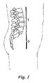
当技術では既知のように、ヒトの解剖学的構造において、脊椎は、一般的には、引張及び圧縮荷重を受け止める可撓性のある柱であり、屈曲動作を可能にすると共に、肋骨、筋肉、及び靭帯の接合場所を提供している。脊柱は、大まかには3つの部分、即ち、頚椎、胸椎、腰椎に分けられる。図1は、健康なヒトの脊柱の腰椎1と仙骨領域3を概略的に示している。脊椎の部分は、椎骨と呼ばれる個々の骨から成り、椎骨同士は、その間に収まっている椎間円板によって分離されている。
This application claims priority from U.S. Provisional Patent Application No. 60 / 534,960 “Opposite Lumbar Arthroplasty” filed Jan. 9, 2004. The following applications also claim priority to the provisional patent application and are related to this application. These series of applications are incorporated herein by reference. US patent application number unknown (patent attorney case number PC1146), filed January 7, 2005, "Spine Arthroplasty Device and Method"; US patent application number unknown (patent attorney case number P21769), filed January 7, 2005 US patent application number unknown (patent attorney case number P21756), filed on Jan. 7, 2005, “split spinal device and method”; US patent application number unknown (patent Case No. P21752), filed Jan. 7, 2005, “Interconnected Spinal Devices and Methods”; US Patent Application No. Unknown (Attorney Case No. P21743), filed Jan. 7, 2005, “Supporting Structure Device and US Patent Application Number Unknown (Attorney Case No. P21765), filed Jan. 7, 2005, “Central Articulating Spinal Apparatus and Method”; and US Patent Application Number More (Attorney Docket No. P21751), 1 May 7, 2005 application, "behind the spine apparatus and method."
As is known in the art, in human anatomy, the spine is generally a flexible column that accepts tensile and compressive loads, allowing flexion movements, as well as ribs, muscles , And provides a place to join the ligament. The spinal column is roughly divided into three parts: cervical, thoracic and lumbar. FIG. 1 schematically shows a
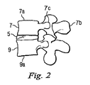
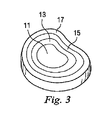
図2は、2つの隣接する椎骨7、9の間に配置された健康な椎間円板5を有する腰椎領域の右側面の一部を示している。所与の何れの関節においても、上側の椎骨を上椎骨と呼び、下側の椎骨を下椎骨と呼ぶ。各椎骨は、重量を支える主要領域である略円筒形の椎体7a、9aと、3つの骨突起、例えば7b、7c、7d(図2ではこの内2つが見える)を備えている。図7Aでは、全ての突起が見えているが、この図に示すように、突起7b、7c、7dは、椎体7の円周方向に間隔を空けた位置から外向きに伸張している。突起は、他にも機能はあるが、特に筋肉と靭帯を接合するための領域を提供している。隣り合う椎骨は、関節面構成要素7e(図2)を介して互いに対して動くが、この関節面構成要素7eは、椎骨の円筒形の椎体から伸張し、屈曲時は互いに重なり合って滑動し脊椎の動きを誘導するようになっている。面関節は2つあり、それぞれ、隣接する椎骨に関わりを持つ上側及び下側関節面構成要素によって画定されている。健康な椎間円板を図3に示している。図3に示すように、椎間円板には4つの領域、即ち、髄核11、遷移領域13、内層線維輪領域15、外層線維輪領域17がある。一般に、内層線維輪領域15と外層線維輪領域17は、その上方及び下方の椎体にしっかりと取り付いた繊維性軟骨質物質の層で構成されている。通常、髄核11は、より水和した状態にある。
FIG. 2 shows a part of the right side of the lumbar region with a healthy
これら椎間円板は、衝撃吸収装置と関節の機能を兼ね備えている。椎間円板は、脊柱が受ける圧縮及び引張荷重を吸収すると同時に、隣接する椎体が、特に脊椎の屈曲(撓む)時に、互いに対して或る制限された量だけ動けるように作られている。この様に、椎間円板は、常に筋肉及び/又は重力による圧力の下にあるので、一般に腰椎の中では「摩耗と断裂」の徴候が現れる最初の部分である。 These intervertebral discs have both an impact absorbing device and a joint function. The intervertebral disc is designed to absorb the compressive and tensile loads experienced by the spinal column, while at the same time allowing adjacent vertebral bodies to move a limited amount relative to each other, particularly when the spine is flexed. Yes. Thus, the intervertebral disc is always the first part of the lumbar spine to show signs of “wear and tear” because it is always under pressure due to muscle and / or gravity.
面関節は脊椎と共に殆ど常に動いているため、面関節変性も普通に起こる。実際に、面関節変性と円板変性は併発する頻度が高い。一般的には、一方が一次的な問題であり、他方は脊椎の機構が変質したことにより生じる二次的問題であるかもしれないが、外科的選択肢を考慮する段階までに、面関節変性と円板変性の両方が通常は発症している。例えば、面関節及び/又は椎間円板の機構が変質したせいで、脊髄の狭窄、変性脊椎すべり症、及び変性脊柱側弯症が引き起こされることもある。 Since face joints are almost always moving with the spine, face joint degeneration also occurs normally. In fact, facet joint degeneration and disc degeneration frequently occur together. In general, one may be a primary problem and the other may be a secondary problem caused by alterations in the vertebral mechanics. Both disc degeneration usually develops. For example, spinal stenosis, degenerative spondylolisthesis, and degenerative scoliosis may be caused by alterations in the facet joint and / or intervertebral disc mechanisms.
上記症状を治療するための外科的処置の1つに、脊椎関節固定術(spinal arthrodesis)(即ち、脊椎固定術(spine fusion))があり、これは前方進入法及び/又は後方進入法の両方で実施されてきた。後方進入法による処置には、現場固定術(in-situ fusion)、後側方的器具使用による融合、経椎間孔腰椎椎体間固定術(transforaminal lumbar interbody fusion)(「TLIF」)及び後方腰椎椎体間固定術(posterior lumbar interbody fusion)(「PLIF」)が含まれる。脊椎体節の固定的融合(solidly fusing)でそのレベルの動きを無くしてしまうと、当面の症候は緩和されるが、患者によっては動きを維持するのが好都合な場合もある。変性した円板又は面関節をそれぞれ人工円板又は人工面関節に外科的に置換することも知られている。しかしながら、既知の装置又は方法には、本開示の実施形態の利点を提供できるものは皆無である。 One surgical procedure for treating the above symptoms is spinal arthrodesis (ie, spine fusion), which includes both anterior and / or posterior approaches. Has been implemented. The posterior approach includes in-situ fusion, fusion using posterior lateral instruments, transforaminal lumbar interbody fusion ("TLIF") and posterior Includes posterior lumbar interbody fusion ("PLIF"). Eliminating that level of movement with solidly fusing vertebral segments will alleviate the immediate symptoms, but it may be convenient to maintain movement in some patients. It is also known to surgically replace a degenerated disc or facet joint with an artificial disc or facet joint, respectively. However, none of the known devices or methods can provide the advantages of the embodiments of the present disclosure.
従って、上記状況は、既知の移植片及び外科処置技法の欠点及び不都合を回避した、改良された脊椎関節形成術の必要性を示している。 Thus, the above situation illustrates the need for an improved spinal arthroplasty that avoids the disadvantages and disadvantages of known graft and surgical techniques.
或る実施形態では、上椎骨と下椎骨の間の連結の少なくとも一部を作成するための人工脊椎関節は、関節運動をする関節に置換するためのアッセンブリを備えている。この関節運動型関節置換アッセンブリは、上椎骨と下椎骨の間の椎間円板空間内へと伸張する前方関節置換構成要素と、第1後方関節置換構成要素と、前方関節置換構成要素と第1後方関節置換構成要素の間に連結された第1ブリッジ構成要素と、を備えている。この人工脊椎関節は、支持関節置換アッセンブリを更に備えている。支持関節置換アッセンブリは、上及び下椎骨の間の椎間円板空間内へと伸張する前方支持構成要素と、第2後方関節置換構成要素と、前方支持構成要素と第2後方関節置換構成要素の間に連結された第2ブリッジ構成要素と、を備えている。前方支持構成要素は、関節運動型関節置換構成要素と係合している。 In certain embodiments, an artificial spinal joint for creating at least a portion of a connection between an upper vertebra and an inferior vertebra includes an assembly for replacement with an articulating joint. The articulating joint replacement assembly includes an anterior joint replacement component that extends into an intervertebral disc space between an upper vertebra and a lower vertebra, a first posterior joint replacement component, an anterior joint replacement component, and a first joint replacement component. A first bridge component coupled between the one posterior joint replacement component. The artificial spinal joint further includes a support joint replacement assembly. The support joint replacement assembly includes an anterior support component that extends into an intervertebral disc space between the upper and lower vertebrae, a second posterior joint replacement component, an anterior support component, and a second posterior joint replacement component. A second bridge component connected between the two. The anterior support component is engaged with the articulating joint replacement component.
別の実施形態では、人工脊椎関節を移植する方法が提供されている。この方法は、椎間円板空間にアクセスするために患者の背部に第1露出部を作成する段階と、椎間円板空間にアクセスするために患者の背部に第2露出部を作成する段階と、第1露出部を通して第1経路に沿って椎間円板空間に人工脊椎関節の関節運動アッセンブリ部分を送り込む段階と、第2露出部を通して第2経路に沿って椎間円板空間に人工脊椎関節の支持アッセンブリ部分を送り込む段階と、関節運動アッセンブリ部分を支持アッセンブリ部分と係合させる段階と、を含んでいる。この実施形態では、第1露出部は第2露出部よりも大きい。 In another embodiment, a method for implanting an artificial spinal joint is provided. The method includes creating a first exposed portion on the patient's back to access the intervertebral disc space and creating a second exposed portion on the patient's back to access the intervertebral disc space. And a step of feeding an articulation assembly portion of the artificial spinal joint along the first path through the first exposed part into the intervertebral disk space along the second path through the second exposed part. Delivering a support assembly portion of the spinal joint and engaging the articulation assembly portion with the support assembly portion. In this embodiment, the first exposed portion is larger than the second exposed portion.
別の実施形態では、上椎骨と下椎骨の間に連結を作成するためのシステムにおいて、上椎骨と下椎骨の間の椎間円板空間内へと、経椎間孔進入法(transforaminal approach)経椎間孔を介して移植するための前方関節運動アッセンブリと、前方関節運動アッセンブリに接続され、椎間円板空間の後方に伸張する第1後方関節運動アッセンブリと、を備えているシステムが提供されている。前方関節運動アッセンブリは、吻側関節運動面と係合している尾側関節運動面を備えており、この尾側と吻側の関節運動面の係合により回転の中心が画定されている。回転の中心は、一般的には、椎間円板空間を通る前後方向中心軸に沿って位置している。 In another embodiment, in a system for creating a connection between upper and lower vertebrae, a transforaminal approach into the intervertebral disc space between the upper and lower vertebrae A system comprising an anterior articulation assembly for implantation via a transvertebral foramen and a first posterior articulation assembly connected to the anterior articulation assembly and extending rearward of the intervertebral disc space is provided. Has been. The anterior articulation assembly includes a caudal articulation surface engaged with the rostral articulation surface, and the center of rotation is defined by the engagement of the caudal and rostral articulation surfaces. The center of rotation is generally located along a central axis in the front-rear direction passing through the intervertebral disc space.
開示されている実施形態は、腰椎の外傷後の、椎間板に起因する、関節面痛又は脊椎すべり症の退行性変化、及び/又は腰椎の複数レベルの運動機能の維持に有用である。 The disclosed embodiments are useful for degenerative changes in articular pain or spondylolisthesis due to intervertebral discs following lumbar trauma and / or maintaining multiple levels of lumbar motor function.
追加的及び代わりの特徴、利点、使用法及び実施形態は、以下の説明、図面及び特許請求の範囲に記載しており、その中で明らかになるであろう。 Additional and alternative features, advantages, usage, and embodiments are described in, and will be apparent from, the following description, drawings, and claims.
各図面は、椎間円板、又は椎間円板と少なくとも1つの対応する面関節との組み合わせを置換するための人工脊椎関節の様々な実施形態を示している。本開示の原理による人工脊椎関節の各種実施形態は、関節置換に陥り易い問題の何れを治療するのにも使用することができ、特に、例えば、腰椎の外傷後の、椎間板に起因する、関節面痛又は脊椎すべり症の退行性変化、及び/又は腰椎の複数のレベルの運動機能維持に使用することができる。 Each drawing shows various embodiments of an artificial spinal joint for replacing an intervertebral disc or a combination of an intervertebral disc and at least one corresponding facet joint. Various embodiments of an artificial spinal joint in accordance with the principles of the present disclosure can be used to treat any of the problems prone to joint replacement, and in particular, joints resulting from an intervertebral disc after trauma of the lumbar spine, for example. It can be used to degenerate changes in facial pain or spondylolisthesis and / or to maintain multiple levels of motor function in the lumbar spine.
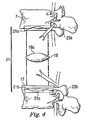
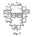
図4−図7は、人工脊椎関節の第1の代表的な実施形態を示している。図4及び図5に示すように、各関節は2つの関節形成用半部から構成され、各半部は、スペーサ又は円板19と保持部21とを有している。保持部21は、第1保持部21aと第2保持部21bを含んでいる。図4に示す例では、第1保持部21aは、第2保持部21bに対して上位(上方)にあり、円板19がその間に収まっている。この代表的な実施形態による人工脊椎関節は、第1保持部と第2保持部それぞれとして2つの半部を有しているが、代わりの実施形態は、人工脊椎関節が、1つの第1保持部材と、1つの第2保持部材と、1つのスペーサを有するように実施してもよいと理解されたい。また、代わりの実施形態は、それぞれに大きさの異なる半部又は2つより多い構成要素で構成されている、第1保持部と、第2保持部と、及び/又は円板とを有する関節形成用装置で実施してもよい旨理解されたい。
4-7 illustrate a first exemplary embodiment of an artificial spinal joint. As shown in FIGS. 4 and 5, each joint is composed of two joint forming halves, and each half has a spacer or
また、図4に示すように、第1保持部21aと第2保持部21bは、2つの隣接する椎骨の間に装着されている。より具体的には、第1保持部は2つの隣接椎骨の内の上側の椎骨の下面に沿って装着され、第2保持部は、2つの隣接する椎骨の内の下側の椎骨の上面上方に装着される。しかしながら、当業者には理解頂けるように、第1保持部と第2保持部は、このような配置に限定されず、ここに図示したものとは異なる位置に配置し及び/又は異なる形状であってもよい。
Moreover, as shown in FIG. 4, the 1st holding |
椎骨の残っている終板に接する関節形成用装置の保持部21a、21bの表面は、骨の内部成長とそれらの間の堅固な接合を促すために、ビード付き材料で被覆され又はプラズマ噴霧されていてもよい。具体的には、骨の内部成長を促す面は、コバルトクロムモリブデン合金に、チタン/カルシウム/リン酸塩の二重被覆、メッシュ面、又は他の効果的な面仕上げを施したものでもよい。代わりに、又は組み合わせて、ポリメチルメタクリレート(PMMA)のような接着剤又はセメントを、終板の一方又は両方に移植片の全体又は一部を固定するために使用してもよい。
The surfaces of the
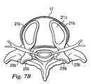
後で詳しく説明するが、外層線維輪領域17(例えば、図4、7B参照)の大部分、或る実施形態では約300度は、終板の下部分にそのまま残され、これは、骨の内部成長が起こって保持部を相手方の各椎骨にしっかりと取り付けるまで、下側保持部を所定の位置に保持するストッパとして機能する(図4は、残されている外層線維輪17の一部しか示していない)。対照的に、従来の前方関節形成術では、通常、外層線維輪17の約270度が取り除かれる。また、当面の固定には椎弓根スクリュー(pedicle screws)も使用することができ、これについては後で論じる他の実施形態に結び付けて詳しく説明する。
As will be described in detail later, the majority of the outer annulus region 17 (see, eg, FIGS. 4, 7B), in some embodiments, approximately 300 degrees is left intact in the lower portion of the endplate, It functions as a stopper to hold the lower holding part in place until ingrowth occurs and the holding part is firmly attached to each vertebra of the other side (FIG. 4 shows only a part of the remaining
本開示の各種実施形態では、第1保持部21aと第2保持部21bは、両者の間に円板19を保持できる構造に作られている。例えば、2つの凸状面19aを備えた円板19の場合、第1保持部21aと第2保持部21bは、それぞれ、円板19が保持される空間を画定する凹状面21cを有している。例えば、図4に示す代表的な実施形態では、円板19の上側凸状面19aは、第1保持部21aの凹状面21cにより画定されている陥凹部内に嵌め込まれ、円板19の下側凸状面19bは、第2保持部21bの凹状面21cにより画定されている陥凹部内に嵌め込まれる。
In various embodiments of the present disclosure, the
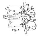
図5は、組み立て済みの代表的な人工脊椎関節の、関節形成用半部が両方共に所定の位置に配置された状態の前面図を示しており、図6は、図5に示す組み立て済み人工脊椎関節の側面図を示している。図5と図6に示すように、円板19は、第1保持部21aと第2保持部21bの間に保持されている。なお、円板19は第1保持部21aと第2保持部21bの間に保持されているが、円板19は、第1保持部21aの対応する面21aと第2保持部21bとにより画定された空間内で自由に滑動できるものと理解されたい。この様にして、隣接する椎骨の間の制限された動きを実現している。
FIG. 5 shows a front view of a representative assembled artificial spinal joint with both arthroplasty halves in place and FIG. 6 shows the assembled artificial prosthesis shown in FIG. Fig. 6 shows a side view of a spinal joint. As shown in FIGS. 5 and 6, the
図4、5、6に示す代表的な実施形態では、円板19は、第1保持部21aと第2保持部21bの間に挿入される別体の構成要素である。しかしながら、下に論じるように、スペーサ又は円板19は、第1保持部21aと第2保持部21bの一方又は両方と共に形成してもよいし、一体に形成してもよいと理解されたい。
In the representative embodiment shown in FIGS. 4, 5, and 6, the
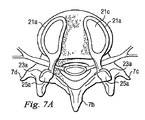
本開示の代表的な実施形態では、図4、6、7A、7Bを見れば良く分かるように、人工脊椎関節の各保持部は、第1人工関節面構成要素23aと第2人工関節面構成要素23bを含んでいる。図7Aと図7Bに示すように、第1人工関節面構成要素23aは面25aを有し、対応する第2人工関節面構成要素23bは面25bを有しており、面25aが面25bに嵌り込んで隣接する椎骨を安定化させると共に、各椎骨の他方の椎骨に対する可動性を留保し及び案内するように構成されている。上側及び下側保持部21a及び21bの各セットは、一対の関節面構成要素23a、23bを有し、それらは一体となって面関節を画定している。この実施形態による関節面を用いた関節全置換術(total joint replacement)の場合、左右の関節形成用装置は、後方から見た場合に2つの隣接する面関節を画定することになる。
In a representative embodiment of the present disclosure, as can be understood by looking at FIGS. 4, 6, 7A, and 7B, each holding portion of the artificial spinal joint includes a first artificial
人工面関節が設けられているか否かに関わりなく、関節形成用装置の左右半部に関係付けられた各上側及び下側保持部は、互いに完全に独立している。即ち、図7Aに示すように、例えば、各半部に対応付けられた第1保持部21aは、互いに直接接触しているわけではない。図7Bに示す第2保持部21bに関しても同じことが当てはまる。しかしながら、当業者には理解頂けるように、人工面関節を含んでいる本開示の実施形態においてさえ、各半部の第1保持部21aの少なくとも一部、及び/又は各半部の第2保持部21bの少なくとも一部は、互いに直接接触し及び/又は接続されていてもよく、これについては図17から図18の説明に関連付けて更に詳しく説明する。
Regardless of whether artificial face joints are provided or not, the upper and lower holding portions associated with the left and right halves of the arthroplasty device are completely independent of each other. That is, as shown in FIG. 7A, for example, the
また、本開示の様々な実施形態では、円板19、第1保持部21a、及び第2保持部21bは、圧縮力及び引張力を伝達する接続をやり易くすると共に、隣接面それぞれの間で略横方向に上記のような滑動運動ができるようにするのに適していれば、どの様な材料で作ってもよい。例えば、第1の実施形態では、第1保持部21aと第2保持部21bは、通常、ステンレス鋼、チタン、及びコバルトクロムのような外科用移植片適している金属又は金属合金、又は炭素繊維のような複合材料、又はポリエーテルエーテルケトン(PEEK)のようなプラスチック材料、又は他の適した材料で作られる。円板は、高分子量ポリエチレン又はPEEKのようなプラスチックから、又はセラミック、金属、及び限定するわけではないが、炭素繊維、ゴム、又は他の適した材料のような天然又は合成繊維から作られる。一般的に、面の滑動特性を維持し易くするため、面は、研磨し及び/又は被覆して滑らかな面にする。例えば、面が金属製の場合、金属面は研磨された金属でもよい。
In various embodiments of the present disclosure, the
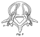
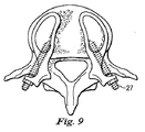
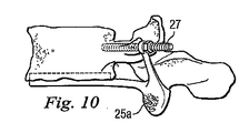
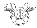
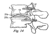
図8から図14は、人工脊椎関節の第2の実施形態を示している。第1の実施形態と異なる特徴だけをここでは詳しく説明する。第2の代表的な実施形態では、例えば椎弓根スクリュー(pedicle screws)27のような固定用構成要素が設けられ、第1保持部21a及び/又は第2保持部21bそれぞれの間に、対応する椎骨に対してよりしっかりした且つ直接的な接合を形成している。更に、この実施形態は、一方の保持部、ここでは下側保持部21bと一体に作られた円板19を示している。円板19は、その保持部と同じ材料で一体成形してもよいし、似た又は異なる材料で別個に成形した後、保持部に永続的に接合して一体の装置を形成してもよい。この実施形態では、円板19と保持部は全て金属で作られている。
8 to 14 show a second embodiment of the artificial spinal joint. Only the features different from the first embodiment will be described in detail here. In the second exemplary embodiment, a fixing component such as a
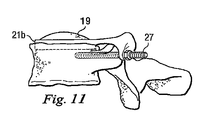
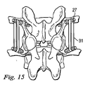
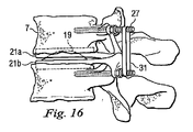
図15と図16は、人工脊椎関節の第3の実施形態を示している。第3の代表的な実施形態では、例えばテンションバンド31のような追加の固定用構成要素が設けられ、第1保持部21aを第2保持部21bに締結することによって隣接する椎骨の間の可動性を制限する、後靭帯の機能を補い、又はこれに置き換えている。図15と図16に示すように、後部テンションバンド31は、対応する椎弓根スクリュー27同士の周りに、又は他の都合のよい取り付け箇所に巻きつけることにより設けられる。
15 and 16 show a third embodiment of the artificial spinal joint. In a third exemplary embodiment, an additional fixation component, such as a
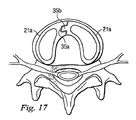
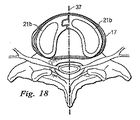
図17と図18は、人工脊椎関節の第4の実施形態を示している。図17と図18に示す代表的な実施形態では、人工脊椎関節は、人工関節面構成要素を除いて、上に論じた特徴を全て備えている。この実施形態では、天然の面関節が留保されている。靭帯のテンションバンドが無傷のまま残される実施形態もある。加えて、この実施形態は、第1保持部21aと第2保持部21bの配置を維持するのに役立つ各上側及び下側保持部の間の前方正中線接合の具体的な事例を含んでいる。
17 and 18 show a fourth embodiment of the artificial spinal joint. In the exemplary embodiment shown in FIGS. 17 and 18, the artificial spinal joint has all of the features discussed above, except for the artificial joint surface components. In this embodiment, the natural facet joint is reserved. In some embodiments, the ligament tension band is left intact. In addition, this embodiment includes a specific case of a front midline junction between each upper and lower holding part that helps to maintain the arrangement of the first holding
図17と図18は、第1保持部21aに、第2保持部21bに形成された対応する嵌め込み部分と相補形のロック・キー式のパターンを設けることができることを示している。より具体的には、第1保持部21aの一方の半部は、U字形状部35aの外側境界を有しており、対応する第1保持部21aの他方の半部は、U字形状部35aに嵌る突き出た部分35bの形をした外側境界を有している。その結果、第1保持部21a、21bの各半部は、所定の位置に維持される。しかしながら、上側又は下側保持部は、移植し易くし及び/又は関節を概ね安定した対称的構成に形成し及び/又は維持するのを支援する何らかのやり方で、椎体間空間、例えばその正中線前方部で、一体に嵌め合わせ、及び/又は接続してもよい。図18に示す下側の終板に残された線維輪17により与えられる内向きの力によって、下側保持部の間にそのような接合を作り出すことがなおさら重要である。各下側保持部の間の正中線接合は、保持部を正中線37に向けて移動させようとする外層線維輪の力に抵抗することになる。
17 and 18 show that the
各種代表的実施形態に示すように、ロックとキーのように一体に嵌り合って各部の互いに対する配置を維持する第1及び/又は第2保持部以外の部分も、人工脊椎関節の各半部は、椎骨の正中線37を中心に概ね対称になっている。
As shown in various representative embodiments, the portions other than the first and / or second holding portions that fit together and maintain the arrangement of the portions relative to each other, such as a lock and a key, are also included in each half of the artificial spinal joint. Are generally symmetrical about the
繰り返すが、これらの代表的実施形態は、単に説明を目的としており、本発明の可能な設計、実施例、変更及び使用例を網羅することを意図しているわけではない。また、本開示の或る実施形態に関連して説明した特徴は、上に明示的に述べていなくとも、他の実施形態に結び付けて使用することができる。 Again, these exemplary embodiments are for illustrative purposes only and are not intended to be exhaustive of possible designs, examples, modifications and uses of the invention. Also, features described in connection with certain embodiments of the present disclosure may be used in conjunction with other embodiments, even if not explicitly stated above.
上に論じたことから当業者には自明であろうが、人工関節の移植に使用するのに適した外科処置の手法を以下に簡単に説明する。一般的には、上で論じたように、人工脊椎関節は、既知のTLIF又はPLIF手法に類似の後方孔横断式進入法を用いて体内に移植される。この進入法によれば、患者の背部に正中線切開のような切開を施し、この孔を経由して罹患した円板の一部又は全部と周辺組織を取り出す。面関節を一部でも置換するか否かによるが、天然の面関節を削って人工面関節用の空間を作成する。次いで、人工脊椎関節の各半部を、左右の孔横断開口部を通してそれぞれ一個ずつ挿入する。即ち、関節面構成要素を備えている場合もいない場合もあるが、上側及び下側保持部と、人工円板が別体で設けられていればその人工円板と、を含んでいる人工脊椎関節の各部品を、孔を通して適切な椎間空間に配置する。人工関節の各部品は、完全に別々でもよいし、又は孔を通して挿入する前にその内の2つ又は3つ以上を、布又は当技術で既知の材料で一体に繋ぎ又はパッケージ化してもよい。天然の円板の外層線維輪の少なくとも一部を残しておける場合、人工脊椎関節の各側の下側保持部は、線維輪の対応する部分に当接するように挿入する。正中線前方接合が設けられている場合、保持部材の左右半部は、嵌め合わされ、外層線維輪で所定の位置に保持される。すると、線維輪の残り部分は、それが処置前に在ったのと実質的に同じ場所に位置することになる。 As discussed above, as will be apparent to those skilled in the art, a surgical procedure suitable for use in artificial joint implantation is briefly described below. In general, as discussed above, an artificial spinal joint is implanted into the body using a posterior foramen approach similar to known TLIF or PLIF techniques. According to this approach, an incision such as a midline incision is made on the patient's back, and part or all of the affected disc and surrounding tissue are removed via this hole. Depending on whether or not the face joint is partially replaced, the natural face joint is cut to create a space for the artificial face joint. Next, one half of each artificial spinal joint is inserted through each of the left and right hole-crossing openings. That is, an artificial spine including an upper and lower holding portion and an artificial disc if the artificial disc is provided separately, which may or may not include a joint surface component. Each part of the joint is placed in the appropriate intervertebral space through the hole. The components of the prosthesis may be completely separate, or two or more of them may be joined or packaged together with a cloth or material known in the art prior to insertion through the hole. . When at least a part of the outer layer annulus of the natural disc can be left, the lower holding part on each side of the artificial spinal joint is inserted so as to abut against the corresponding part of the annulus. When the midline front joint is provided, the left and right halves of the holding member are fitted together and held in place by the outer layer annulus. The rest of the annulus will then be located at substantially the same location as it was before the procedure.
また、天然円板の線維輪全体を取り除かねばならない場合、又は残っている線維輪が不十分である場合は、例えば、人工脊椎関節の諸部品が確実に定位置に留まるように、椎弓根スクリューを使用している本開示の実施形態を用いることができる。なお、当業者には理解頂けるように、後方進入法の利点が限定されることにはなるが、人工関節は、前方進入法又は前方進入法と後方進入法の組み合わせにより実施することもできる。例えば、人工脊椎関節の部品の一部を前方進入法で挿入し、他の部品を後方進入法で挿入してもよい。前方及び後方進入法で配置された部品は、図17と図18に示す実施形態と同じように一体に嵌め合せることができる。 Also, if the entire annulus of the natural disc has to be removed, or if the remaining annulus is insufficient, for example, the pedicle will ensure that the components of the prosthetic spinal joint remain in place. Embodiments of the present disclosure using screws can be used. As can be understood by those skilled in the art, the advantages of the backward approach method are limited, but the artificial joint can be implemented by the forward approach method or a combination of the forward approach method and the backward approach method. For example, some of the parts of the artificial spine joint may be inserted by the forward approach method, and other parts may be inserted by the backward approach method. The parts arranged in the forward and backward approach can be fitted together as in the embodiment shown in FIGS.
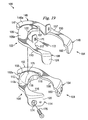
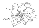
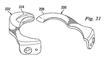
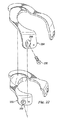
次に、図19と図20に示す実施形態では、人工椎間関節100は、椎骨7、9の間に挿入される2つの関節形成用半部102、104を含んでいる。関節形成用半部102は、関節運動型関節置換アッセンブリであり、吻側前方構成要素106と、吻側後方関節構成要素108と、前方構成要素106と後方構成要素108の間を伸張する吻側ブリッジ110と、を含んでいる。吻側前方構成要素106は、更に、凸状の壁部107を含んでいる。関節形成用半部102は、更に、尾側前方関節構成要素112と、尾側後方関節構成要素114と、前方構成要素112と後方構成要素114の間を伸張する尾側ブリッジ116と、を含んでいる。尾側前方構成要素112は、更に、凸状の壁部115を含んでいる。吻側前方関節構成要素106は骨接触面106aを含んでおり、尾側前方関節構成要素112は骨接触面112aを含んでいる。
19 and 20, the artificial intervertebral joint 100 includes two
「吻側(rostral)」及び「尾側(caudal)」という用語は、幾つかの実施形態で、それら実施形態の構成要素の位置を説明するのに使用している。吻側は、当技術では通常、頭部に向く位置を説明するのに用いられ、尾側は、尾部又は足に向く位置を説明するのに用いられており、吻側と尾側は、ここでは単に図示の実施形態の構成要素の相対位置に対する修飾語として用いている。例えば、吻側構成要素は、図示の関節の一方の側にあり、尾側は当該関節の別の側にある。構成要素は、図示の実施形態を説明するために吻側及び尾側と称しているからといって、患者の解剖学的構造に対する装置又は方法の適用の方向を限定することも、特許請求の範囲を何れかの装置又は方法に限定することも、意図しているわけではない。 The terms “rostral” and “caudal” are used in some embodiments to describe the location of the components of those embodiments. The rostral side is usually used in the art to describe the position facing the head, the caudal side is used to describe the position facing the tail or foot, the rostral side and the caudal side here However, it is simply used as a modifier for the relative positions of the components in the illustrated embodiment. For example, the rostral component is on one side of the illustrated joint and the caudal side is on the other side of the joint. Claiming that the components are referred to as rostral and caudal to describe the illustrated embodiment also limits the direction of application of the device or method to the patient's anatomy. It is not intended to limit the scope to any device or method.
この実施形態では、吻側ブリッジ110は、神経根を外に出すための出口ポータルと人工孔を作成するために凹凸117を含んでいる。ブリッジ110、116の何れか、具体的には尾側ブリッジ116は、天然の椎弓根を補助又は置換する「スーパー」又は人工椎弓根であってもよい。更にこの実施形態では、尾側前方関節構成要素112は、湾曲した突起118のような尾側関節運動面を含んでおり、尾側後方関節構成要素114は、後方関節運動部120を含んでいる。吻側前方関節構成要素106は、湾曲突起部118を受け入れるように作られた前方ソケットのような吻側関節運動面を含んでいる。湾曲突起部118の曲率半径を前方ソケット122の曲率半径とガタの無いように整合させて、拘束のきついボール・ソケット型係合を作成している。前方ソケット122を湾曲突起部118と係合させると、回転中心125が決まる。代わりの実施形態では、湾曲突起部に比較してソケットの曲率半径を大きくすることにより、湾曲突起部がソケット内で並進できるようにしている。
In this embodiment, the
吻側後方関節構成要素108は、後方関節運動部120と係合するように作られた後方ソケット124を含んでいる。後方関節運動部120の曲率半径は、後方ソケット124の曲率半径よりも小さいので、後方関節構成要素108、114の間の運動を許容し且つ結合を制限している。後方ソケット124と後方関節運動部120の曲率半径は、関節形成用半部102の共通の回転中心から放射されていてもよい。この実施形態では、後方ソケット124の曲率半径は比較的大きいので、得られた関節は拘束が緩い。代わりの実施形態では、尾側後方構成要素の後方突起部のガタの無い曲率半径が、ガタの無い曲率半径を有する吻側後方構成要素と嵌り合って、拘束のきつい後方関節を作成している。
The rostral posterior
関節形成用半部104は、支持関節置換アッセンブリであり、吻側前方支持構成要素146と、吻側後方関節構成要素148と、前方構成要素146と後方構成要素148の間を伸張する吻側ブリッジ150と、を含んでいる。吻側前方構成要素146は、更に、凹状の壁部147を含んでいる。関節形成用半部104は、更に、尾側前方支持構成要素152と、尾側後方関節構成要素154と、前方構成要素152と後方構成要素154の間を伸張する尾側ブリッジ156と、を含んでいる。尾側前方構成要素152は、更に、凹状の壁部155を含んでいる。吻側前方支持構成要素146は、骨接触面146aを含んでおり、尾側前方支持構成要素152は、骨接触面152aを含んでいる。
The
この実施形態では、吻側ブリッジ150は、神経根を外に出すための出口ポータルと人工孔を作成するために凹凸157を含んでいる。この実施形態でも、尾側後方関節構成要素154は、後方関節運動部160を含んでいる。吻側後方関節構成要素148は、後方関節運動部160と係合するように作られた後方ソケット162を含んでいる。後方関節運動部160の曲率半径は、後方ソケット162の曲率半径よりも小さいので、後方関節構成要素148、154の間の運動を許容し且つ結合を制限している。後方ソケット162と後方関節運動部160の曲率半径は、関節形成用半部104の共通の回転中心から放射されていてもよい。この実施形態では、後方ソケット162の曲率半径は比較的大きいので、得られた関節は拘束が緩い。代わりの実施形態では、尾側後方構成要素の後方突起部のガタの無い曲率半径が、ガタの無い曲率半径を有する吻側後方構成要素と嵌り合って、拘束のきつい後方関節を作成している。
In this embodiment, the
前方構成要素106、112、146、152及びブリッジ構成要素110、116、150、156の大きさと形状は、後方外科的進入法又は経椎間孔外科的進入法の制約により制限される。例えば、前方構成要素106、112、146、152は、後方の外科的露出部、カムビン(Kambin)の三角形、及び他の神経要素の間を通過させて装着できるようにしながら、最大の椎骨終板面積を覆って荷重を分散し沈下を少なくするように構成される。ブリッジ構成要素110、116、150、156の幅も、カムビンの三角形を通過して、神経要素と共存させるために、できる限り小さくされている。
The size and shape of the
関節形成用半部102、104は、更に、椎骨7、9に固着するための造形を備えている。しかしながら、代わりの実施形態では、固定用の造形は省かれていると理解されたい。関節形成用半部104は、関節形成用半部102と実質的に同様な固定用の造形を含んでいるので、これ以上詳しくは説明しない。関節形成用半部102は、吻側前方関節構成要素106から吻側に伸張する接続用構成要素170を含んでいる。この実施形態の接続用構成要素170は、スクリュー172のような骨ファスナを受け入れるようになっている孔を含んでいる。接続用構成要素170は、スクリュー172を筒状の椎体7aに固着することができるような向きに配置されている。
The arthroplasty halves 102, 104 are further provided with a shape for fixing to the
関節形成用半部102は、更に、尾側後方関節構成要素114に取り付けられるか、又はこれと一体に形成された接続用構成要素174を含んでいる。この実施形態の接続用構成要素174は、スクリュー176のような骨ファスナを受け入れるようになっている孔を含んでいる。接続用構成要素174は、スクリュー176が、中心軸から角度の付いた又は斜めに向いた、椎弓根を通して画定された経路を通るように、スクリュー176を椎弓根外的(extrapedicularly)に挿入できるような向きに配置されている。この実施形態では、スクリューは、椎弓根の壁を通過して、強力な皮質固定を実現する。椎弓根外固定(extrapedicular fixation)は、略後方−前方に椎弓根を通して画定された軸を下る経路を通らず椎弓根に固定されるどの様な固定でもよい。骨ファスナー172、176は、関節運動、軟組織及び天然構造に干渉しないように、埋め込まれる。
The
或る代わりの実施形態では、後方構成要素から伸張する接続用構成要素は、スクリューが、略後方−前方に椎弓根を通して画定された軸を下って椎弓根内に挿入される向きに配置されている。なお、他の代わりの実施形態では、接続用構成要素は、関節形成用半部の様々な構成要素から、様々な角度で、様々な方向に伸張していると理解されたい。例えば、接続用構成要素は、吻側前方関節構成要素からではなく吻側ブリッジから伸張していてもよい。 In an alternative embodiment, the connecting component extending from the posterior component is oriented so that the screw is inserted into the pedicle below the axis defined through the pedicle approximately posterior-to-anterior. Has been. It should be understood that in other alternative embodiments, the connecting components extend from the various components of the arthroplasty half at various angles and in various directions. For example, the connecting component may extend from the rostral bridge rather than from the rostral anterior joint component.
図19と図20に示すように、関節運動型関節置換アッセンブリ102の吻側構成要素106、108、110は、一体に形成されている。モジュール式の代わりの実施形態では、これら構成要素は、互いに取り外し可能に連結されていると理解されたい。例えば、吻側前方関節構成要素は、ブリッジとは別に装着してもよい。前方構成要素を所定の位置に配置した後、例えば、螺合接続、ボルト式接続、又はラッチ式接続のような当技術では既知の機構で、ブリッジを前方構成要素に取り付けてもよい。次いで、モジュール式吻側構成要素を、同様の締結機構でブリッジに取り付けて、関節形成用半部の吻側部分が完成する。同じように、尾側構成要素又は支持関節置換アッセンブリの構成要素はモジュール式でもよい。
As shown in FIGS. 19 and 20, the
関節形成用半部102、104は、適した生体適合性を有する材料であれば、コバルト−クロム合金、チタン合金、ニッケルチタン合金、及び/又はステンレス鋼合金のような金属を含め、どの様な材料で形成してもよい。酸化アルミニウム又はアルミナ、酸化ジルコニウム又はジルコニア、粒子状ダイアモンドの圧縮物、及び/又は熱分解性炭素のようなセラミック材料も適している。ポリエーテルエーテルケトン(PEEK)、炭素強化PEEK、又はポリエーテルケトンケトン(PEKK)のようなポリアリルエーテルケトン(PAEK)系のあらゆる種類;ポリスルフォン;ポリエーテルイミド;ポリイミド;超高分子量ポリエチレン(UHMWPE);及び/又は架橋UHMWPEを含むポリマー材料も使用することができる。この関節形成半部102、104を備えている各種構成要素は、異なる材料で形成してもよく、従って、金属と金属、金属とセラミック、金属とポリマー、セラミックとセラミック、セラミックとポリマー、ポリマーとポリマーの積層構造とすることもできる。関節形成用半部102、104の骨接触面は、移植された人工器官の固定を強化する造形又は被覆を含んでいてもよい。例えば、面は、化学的エッチング、ビード吹き付け、サンダー仕上げ、研削、セレーション加工、及び/又はダイヤモンド切削などで、粗面加工を施してもよい。関節形成用半部102、104の骨接触面の全て又は一部は、骨の内部成長及び固定を促進するため、ヒドロキシアパタイト(HA)、リン酸三カルシウム(TCP)、及び/又は炭酸カルシウムのような生体適合性を有する骨誘導性の物質で被覆してもよい。代わりに、形質転換成長因子(TFG)ベータ上科由来のタンパク質、又はBMP2又はBMP7のような骨形態形成タンパク質のような骨誘発性被覆を使用してもよい。他の適した造形としては、スパイク、リッジ、及び/又は他の面の肌理が含まれる。 The arthroplasty halves 102, 104 may be any suitable biocompatible material, including metals such as cobalt-chromium alloys, titanium alloys, nickel titanium alloys, and / or stainless steel alloys. You may form with a material. Also suitable are ceramic materials such as aluminum oxide or alumina, zirconium oxide or zirconia, compacts of particulate diamond, and / or pyrolytic carbon. Any kind of polyallyl ether ketone (PAEK) system such as polyetheretherketone (PEEK), carbon reinforced PEEK, or polyetherketoneketone (PEKK); polysulfone; polyetherimide; polyimide; ultra high molecular weight polyethylene (UHMWPE) ); And / or polymeric materials including cross-linked UHMWPE can also be used. The various components comprising the arthroplasty halves 102, 104 may be formed of different materials, and thus, metal to metal, metal to ceramic, metal to polymer, ceramic to ceramic, ceramic to polymer, polymer and A laminated structure of polymers can also be used. The bone contacting surfaces of the arthroplasty halves 102, 104 may include features or coverings that enhance fixation of the implanted prosthesis. For example, the surface may be roughened by chemical etching, bead spraying, sanding, grinding, serration, and / or diamond cutting. All or part of the bone contacting surfaces of the arthroplasty halves 102, 104 may be made of hydroxyapatite (HA), tricalcium phosphate (TCP), and / or calcium carbonate to promote bone ingrowth and fixation. You may coat | cover with the osteoinductive substance which has such biocompatibility. Alternatively, osteoinductive coatings such as proteins from the transforming growth factor (TFG) beta superfamily or bone morphogenic proteins such as BMP2 or BMP7 may be used. Other suitable features include spikes, ridges, and / or other surface textures.
人工椎間関節100は、以下に述べるように、椎骨7、9の間に装着される。一般に、人工椎間関節100は、既知のTLIF又はPLIFと同様の手法で後方経椎間孔進入法を使って体内に移植される。一般的に、PLIF進入法の方が正中寄りであり、椎骨内空間にアクセスするためには、横切っている神経根及び硬膜をより大きく後退させることになる。これら構造体の間の空間は、カムビンの三角形として知られている。TLIF進入法は、通常、もっと斜め方向になるので、出て行く神経根を後退させるのは少なくて済み、横切っている構造体の後退幅が小さいので硬膜外出血も少なくて済む。出て行く神経根の位置の上方且つカムビンの三角形の外側で、更に側方寄りの進入法を用いて、内空間にアクセスすることもできる。幾つかの事例では、関節面を切除せずに、更に側方寄りの進入法によって、内空間にアクセスすることもできる。また、腰筋を通る直接側方進入法も、既知である。この進入法は、後方の神経要素を完全に回避する。本発明の実施形態は、上記一般的な進入法の何れを利用する場合も想定している。
The artificial facet joint 100 is mounted between the
上記進入法の少なくとも1つにより、患者の背部に正中切開のような切開を施して、罹患した円板の一部又は全部を周辺組織と共に孔を経由して取り出す。椎骨9の上終板面を削り、やすりをかけ、そうでなければ切除して、尾側前方骨接触面112aのプロフィールと整合させて、椎骨9の上終板面に作用する応力分布を正規化し、及び/又は骨の内部成長に先立つ初期固定を提供する。椎骨9の終板に前処理を施すことにより、面は平坦化され、又は、面輪郭が、ポケット、溝、又は骨接触面112a上の対応する造形に整合するものとなる。椎骨7の下終板は、出て行く神経根及び背根神経節が許容する範囲まで、吻側前方関節構成要素106を受け入れるように同様に前処理される。面関節を置換するか否かにより、椎骨7、9の天然の面関節を仕上げて、後方構成要素108、114のための空間を作り出す。
By at least one of the above approaches, an incision, such as a midline incision, is made on the patient's back, and part or all of the affected disc is removed through the hole with the surrounding tissue. The upper end plate surface of the vertebra 9 is shaved, filed, otherwise resected and aligned with the profile of the caudal anterior
次いで、人工椎間関節100の人工関節置換アッセンブリ102を、例えば左の経椎間孔の露出部(transforaminal exposure)を通して個別に挿入する。即ち、吻側及び尾側前方関節構成要素106、112を含んでいる人工関節置換アッセンブリ102の各部品を、それぞれ孔に通して、略円筒状椎体7a、9aの間の適切な椎間円板空間に配置する。前方関節構成要素106、112は、「インゲン豆」TLIFグラフトに使用されているものとよく似た湾曲経路に沿って送り込まれる。椎間円板空間内で、前方関節構成要素106、112は、前方ソケット122が湾曲突起部118と係合し、回転の中心125が、椎間円板空間を通る横方向に中心合わせされた前後方向軸127に概ね沿って位置するように、配置される。挿入時、関節運動型関節置換アッセンブリ102の各部品は、完全に別々でもよいし、又は孔を通して挿入する前にその内の2つ又は3つ以上を、布又は当技術で既知の材料により一体に繋ぎ又はパッケージ化してもよい。天然の円板の外層線維輪の少なくとも一部を残しておける場合、尾側前方関節構成要素は、線維輪の対応する部分に当接するように挿入する。
The prosthetic
上記のように、前方ソケット122が湾曲突起118と係合することにより形成される前方関節接合は、片側を送り込むことで完成される。支持関節置換アッセンブリ104が挿入できないか、又は一方の側方配置半部だけを使用するのが望ましい場合は、関節運動型関節置換アッセンブリ102は単独で機能する。関節運動型関節置換アッセンブリ102を単独で使用する場合は、回転の中心125は軸127に沿って位置するが、代わりの実施形態では、回転の中心は軸127の一方の側に位置する。前方関節接合のこの種の意図的な側性化は、脊柱側弯症の矯正又は平衡補正を要する他の病的症状を矯正する場合に望ましい楔効果を作り出す。関節運動用と支持用の両方の関節置換アッセンブリを装着する状況では、脊柱側弯症及び同様の病的症状は、高度と形状の異なる前方構成要素同士を使用して修復される。こうすると、関節運動型関節置換アッセンブリは、楔として機能して、支持関節置換アッセンブリとは異なる椎間高を作り出す。
As described above, the front articulation formed by engaging the
ブリッジ110、116は、前方関節構成要素106、112からそれぞれ後方に伸張し、椎間円板空間から後方に伸張している。後方構成要素108、114は、後方ソケット124が後方関節運動部120と係合した状態で、椎間円板空間の後方に配置される。これら後方構成要素108、114は、天然の面関節の機能を置換し又はこれを補う。
次いで、人工椎間関節100の支持関節置換アッセンブリ104は、対側性露出部、例えば右の経椎間孔の露出部、を通して一個ずつ挿入される。即ち、吻側及び尾側前方支持構成要素146、152を含む関節運動型関節置換アッセンブリ104の各部品は、それぞれ対側性孔を通して略円筒形状の椎体7a、9aの間の適切な椎間円板空間に装着される。支持関節置換アッセンブリ104は、関節運動面がないので、関節運動型関節置換アッセンブリ102よりも少ない間隙で済む。この様に、関節運動型関節置換アッセンブリ102を挿入するのに必要な最小間隙は、支持関節置換アッセンブリ104を挿入するのに必要な最小間隙よりも小さく、右側の経椎間孔の露出部は、左側の経椎間孔の露出部よりも小さくてよい。前方支持構成要素146、152も、「インゲン豆」TLIFグラフトで使用されているものと同様の湾曲経路、又は構成要素の形状に対応する他の経路に沿って送り込まれる。支持関節置換アッセンブリ104の各部品は、完全に別々でもよいし、又は孔を通して挿入する前にその内の2つ又は3つ以上を、布又は当技術で既知の材料により一体に繋ぎ又はパッケージ化してもよい。椎間円板空間内で、前方支持構成要素146、152は、前方関節構成要素106、112にそれぞれ接続される。この実施形態では、尾側前方関節構成要素112の凸状壁115は、尾側前方支持構成要素152の凹状壁155と係合状態に配置される。吻側前方関節構成要素106は、吻側前方支持構成要素146に対して同様に配置される。前方支持構成要素146、152は、前方関節運動構成要素106、112の回転中心125を、椎間円板空間内の略中央位置に位置決めして維持する働きをすると共に、前方脊柱に沈下を制限する追加の表面積を提供する働きもする。この実施形態では、凸状壁115と凹状壁155の間の界面、又は凸状壁107と凹状壁147の間の界面において、軸旋回、滑動、又は回転運動を行うことができる。
The supporting
或る代わりの実施形態では、吻側の関節構成要素と支持構成要素だけが接続されている。別の実施形態では、尾側の関節構成要素と支持部関節構成要素だけが接続されている。別の実施形態では、処置中に問題が起きた場合は、対側性露出部は放棄される。従って、関節形成術は、関節運動型関節置換アッセンブリだけを片側から送り込むことによって完了する。ブリッジ150、156は、前方関節構成要素146、152から後方に伸張し、椎間円板空間から後方に伸張する。後方構成要素148、154は、後方ソケット162が後方関節運動部160と係合した状態で、椎間円板空間の後方に配置される。これら後方構成要素148、154は、天然の面関節の機能を置換し又はこれを補う。
In an alternative embodiment, only the rostral joint component and the support component are connected. In another embodiment, only the caudal joint component and the support joint component are connected. In another embodiment, the contralateral exposure is abandoned if a problem occurs during the procedure. Thus, arthroplasty is completed by feeding only the articulating joint replacement assembly from one side.
装着後、関節運動型関節置換アッセンブリ102と支持関節置換アッセンブリ104は、椎骨7、9に固定される。スクリュー172は、接続用構成要素170を通して、略円筒形の椎体7aにねじ込まれる。スクリュー176は、接続用構成要素174を通して挿入され、椎骨9に椎弓根外的に固着され、例えば、スクリュー176は、椎弓根の側壁を通過して強力な皮質固定を実現する。対応するファスナを使用して支持関節置換アッセンブリ104を固定する。なお、スクリューは、関節形成用半部全体を移植し終えた後、又は吻側及び尾側構成要素それぞれが移植された後の何れかに、移植できるものと理解されたい。
After mounting, the articulating
装着された状態では、吻側前方関節構成要素106と尾側前方関節構成要素112により作成される前方ボール・ソケット型関節は、比較的安定し自己心出しする。前方及び後方関節は、両方共、関節形成用半部102が剪断力、特に前後方向の力に抵抗できるようにする。尾側前方関節構成要素112に対する吻側前方関節構成要素106の動きは、後方ソケット124内での後方関節運動部120の変位により制限される。例えば、尾側前方関節構成要素112に対する吻側前方関節構成要素106の側方の並進は、後方関節によって制限される。円筒形椎体7a、9aにより画定される長手方向軸周りの回転運動は、後方関節の拘束と、2つの関節形成用半部102、104により提供される合成的拘束の両方によって制限される。また、後方関節は、どの様な真の側方屈曲自由度にでも制約を課す。
In the mounted state, the anterior ball and socket joint created by the rostral anterior
運動の純粋な自由は、関節運動型関節置換アッセンブリ102の前方関節を通って画定される軸の周りの屈曲−伸展運動に制限される。しかしながら、或る一定の状況の下では、関節100は、上記設計上の制約を乗り越えて、一定の範囲内の横方向、回転方向、及び連結型の運動を許容する。例えば、前方関節構成要素106、112は相互接合から外れ、制限された「リフトオフ」状態になり、厳格な屈曲−伸展運動を超える追加的自由度と連結運動が可能になる。前方関節の自己心出し特性によって、リフトオフが生じた後の再接続と整列が確実に行われる。前方関節構成要素106、112の制限付き接続解除は、後方関節の拘束の程度により調節される。例えば、後方関節の拘束が比較的緩ければ、リフトオフの程度は大きくなる。しかしながら、後方関節の再接続と整列を確実に行うには、後方関節にある程度の制約があったほうが有効であろう。一般に、同一又は同程度の曲率半径を有する各構成要素できつく拘束した、単純な前方配置のボール・ソケット関節は、剪断力に抵抗し並進を制限しながら、屈曲−伸展、側方屈曲、及び捻り運動をできるようにする。後方構成要素に、更に拘束を強めたボール・ソケット関節を加えると、捻り等の自由度に制限を追加することもできる。追加の関節は、運動の自由度を更に制限する。前方又は後方関節が外れるか又は関節運動解除が許容される場合には、追加の自由度が上記のように許容される。ボールとソケットの間の隙間の形状を変えることによっても、追加の運動の自由度が許容されることになる。
Pure freedom of movement is limited to flexion-extension movement about an axis defined through the anterior joint of articulating
前方及び後方関節の頑丈で寛大な構造は、関節形成用半部102、104の配置に整列不良や僅かな精度不良があっても、これを許容する。例えば、前方関節構成要素106、112の自己整列型ボール・ソケット構造は、構成要素同士の或る一定量の整列不良を容認する。従って、構成要素106、112の挿入軌道は、少しならずれてもよい。後方突起120と後方ソケット124の相互作用は、関節形成用半部102、104の間の、平行整列不良及び/又は前後方向整列不良にも対応することができる。
The rugged and generous construction of the anterior and posterior joints allows for misalignment and slight imperfections in the placement of the arthroplasty halves 102,104. For example, the self-aligning ball and socket structure of the anterior
次に、図21に示す実施形態では、人工椎間関節は、以下に記載の相違点を除き、人工椎間関節100と実質的に同じである。この実施形態では、尾側前方関節構成要素202は、スロット204を含んでおり、尾側前方支持構成要素206は、タブ208を含んでいる。スロット204は、タブ208を受け入れて保持するように作られている。スロットは、湾曲していても傾斜していてもよいし、又は、尾側前方関節構成要素202と尾側前方支持構成要素206の間の固定及び選択的取り外し可能な接続を許容する別の種類の係止造形を備えていてもよい。スロット/タブ係合は、尾側前方構成要素又は吻側前方構成要素を接続するのに使用される接続機構の一種でしかない。ねじ付の陥凹部とねじ付のロッドの連結のような、当技術では既知の他の種類の機械的又は固着的接合機構を、接続機構として使用してもよい。
Next, in the embodiment shown in FIG. 21, the artificial facet joint is substantially the same as the artificial facet joint 100 except for the differences described below. In this embodiment, the caudal anterior
次に、図22に示す実施形態では、後方関節構成要素への制御性を高めることにより、前方関節運動構成用要素の制御性を高めている。この代わりの実施形態では、人工椎間関節は、以下に記載の相違点を除き、人工椎間関節100と実質的に同じである。この実施形態では、尾側後方関節構成要素250は、開口(aperture)のような接続用構成要素252を含んでいる。吻側後方関節構成要素254は、細長い開口(elongated aperture)又はスロットのような接続用構成要素256を含んでいる。ブッシュを備えた骨スクリューのような骨ファスナ258を細長開口部256と開口部252に通して椎骨9に挿入する。ファスナ258は、細長開口部256内で並進することができる。従って、前方関節運動型関節置換構成要素は、ファスナ258が開口部256内で並進する際に、或る一定の範囲で屈曲−伸展運動することができる。この実施形態では、接続用構成要素は、椎弓根外的取り付けができるように構成されているが、椎弓根内的及び椎体内固定も、容認可能な選択肢である。
Next, in the embodiment shown in FIG. 22, the controllability of the anterior joint component is enhanced by increasing the controllability to the posterior joint component. In this alternative embodiment, the artificial facet joint is substantially the same as the artificial facet joint 100 except for the differences described below. In this embodiment, the caudal posterior
或る代わりの実施形態では、上記椎間関節は、何れも、更に、吻側前方構成要素から伸張する吻側キール、及び/又は尾側前方関節構成要素から尾側ブリッジに沿って伸張する尾側キールを含んでいる。吻側キールは、椎骨7aの下終板と係合し、尾側キールは椎体9aの上終板及び椎骨9の椎弓根の上面と係合する。なお、椎体7aの下終板は、吻側キールを受け入れるために削られ又は前処理されるものと理解されたい。同様に、椎体9aの上終板と椎骨9の椎弓根は、尾側キールを受け入れる溝を作るために、削られ、彫られ、又は何らかのやり方で前処理される。キールは、骨への接続を助け、関節形成用半部の運動を所望の自由度に制限する。キールは、傾斜した又は半円筒状の断面を有している。2つ以上のキールを所与のどの構成要素に使用してもよいと理解されたい。
In an alternative embodiment, any of the facet joints further includes a rostral keel that extends from the rostral anterior component and / or a tail that extends from the caudal anterior joint component along the caudal bridge. Includes side keel. The rostral keel engages the lower end plate of the
以上、代表的な実施形態を幾つか詳しく説明してきたが、当業者には容易に理解頂けるように、これら代表的な実施形態には、本開示の新規な教示及び利点から実質的に逸脱すること無く、多くの修正を施すことができる。従って、そのような修正及び変更は、全て特許請求の範囲に定義する本発明の範囲内に含まれるものとする。当業者には理解頂けるように、そのような修正及び等価な構造又は方法は、本開示の精神及び範囲を逸脱するものではなく、本開示の精神及び範囲を逸脱することなく、様々な変化、置換、及び変更を施すことができる。「水平」、「垂直」、「上」、「上側」、「下側」、「下」、「左」、及び「右」など、空間についての言及は全て、説明だけを目的としたものであり、本開示の範囲内で変えることができるものと理解されたい。請求項において、手段プラス機能の節は、列挙した機能を実行するものとしてここに説明した構造を、構造的等価物だけではなく等価的構造も含めて、包含するものである。 While several representative embodiments have been described in detail above, as those skilled in the art will readily appreciate, these representative embodiments depart substantially from the novel teachings and advantages of the present disclosure. Many modifications can be made. Accordingly, all such modifications and changes are intended to be included within the scope of this invention as defined in the claims. As those skilled in the art will appreciate, such modifications and equivalent structures or methods do not depart from the spirit and scope of the present disclosure, and various changes, without departing from the spirit and scope of the present disclosure, Substitutions and changes can be made. All references to space, such as “horizontal”, “vertical”, “upper”, “upper”, “lower”, “lower”, “left”, and “right” are for illustrative purposes only. It should be understood that variations can be made within the scope of this disclosure. In the claims, the means-plus-function section includes the structures described herein as performing the listed functions, including not only structural equivalents but also equivalent structures.
Claims (26)
前記上椎骨及び前記下椎骨の間の椎間円板空間内に配置するための前方関節置換構成要素と、第1後方関節置換構成要素と、前記前方関節置換構成要素及び前記第1後方関節置換構成要素の間で連結された第1ブリッジ構成要素とを備えている、関節運動型関節置換アッセンブリと、
前記上椎骨及び前記下椎骨の間の椎間円板空間内に配置するための前方支持構成要素と、第2後方関節置換構成要素と、前記前方支持構成要素及び前記第2後方関節置換構成要素の間で連結された第2ブリッジ構成要素とを備えている、支持関節置換アッセンブリとを備え、
前記前方支持構成要素が、前記前方関節置換構成要素と係合するするようになっている、人工脊椎関節。 In an artificial spinal joint for creating at least part of the connection between the upper and lower vertebrae,
An anterior joint replacement component for placement in an intervertebral disc space between the upper vertebra and the lower vertebra, a first posterior joint replacement component, the anterior joint replacement component and the first posterior joint replacement An articulating joint replacement assembly comprising a first bridge component coupled between the components;
An anterior support component for placement in an intervertebral disc space between the upper vertebra and the lower vertebra, a second posterior joint replacement component, the anterior support component and the second posterior joint replacement component A support joint replacement assembly comprising a second bridge component coupled between
An artificial spinal joint, wherein the anterior support component is adapted to engage the anterior joint replacement component.
後方ソケットを含んでいる吻側後方構成要素と、
後方関節運動部を含んでいる尾側後方構成要素と、を備えており、
前記後方関節運動部は、前記後方ソケットと関節運動するようになっている、請求項1に記載の人工脊椎関節。 The first posterior joint replacement component is
A rostral posterior component including a posterior socket;
A caudal posterior component including a posterior articulation section,
The artificial spinal joint according to claim 1, wherein the posterior articulation unit is adapted to articulate with the posterior socket.
前記後方関節運動部は開口部を備えており、
前記ファスナは前記開口部を通して、前記上椎骨又は前記下椎骨に挿入されるようになっており、更に、前記ファスナの少なくとも一部は、前記後方ソケットと関節運動するようになっている、請求項12に記載の人工椎間関節。 It also has a fastener,
The posterior articulation section comprises an opening;
The fastener is adapted to be inserted into the upper or lower vertebra through the opening, and at least a portion of the fastener is adapted to articulate with the posterior socket. 12. The artificial facet joint according to 12.
前記上椎骨及び前記下椎骨の間の椎間円板空間内へと伸張する前方関節置換構成要素と、
前記前方関節置換構成要素に連結され、前記前方関節置換構成要素から後方に、前記椎間円板空間を越えて伸張するブリッジ構成要素と、
前記ブリッジに連結されている後方関節置換構成要素であって、後方ソケットと係合する後方突起部を含んでいる後方関節置換構成要素とを備え、
前記ブリッジ及び前記後方関節置換構成要素が、前記上椎骨と前記下椎骨との間に画定されている横方向に中心合わせされた前後方向軸の一方の側に配置されるようになっている、人工脊椎関節。 In an artificial spinal joint for creating at least part of the connection between the upper and lower vertebrae,
An anterior joint replacement component extending into the intervertebral disc space between the upper vertebra and the lower vertebra;
A bridge component coupled to the anterior joint replacement component and extending posteriorly from the anterior joint replacement component beyond the disc space;
A posterior joint replacement component coupled to the bridge, comprising a posterior protrusion for engaging a posterior socket; and a posterior joint replacement component comprising:
The bridge and the posterior joint replacement component are arranged on one side of a laterally centered anteroposterior axis defined between the upper vertebra and the lower vertebra; Artificial spinal joint.
前記上椎骨及び前記下椎骨の間の椎間円板空間で関節運動ができるようにする第1手段と、
前記椎間円板空間の後方で関節運動ができるようにする第2手段と、
前記第1手段及び前記第2手段の間を連結するための第3手段と、
前記椎間円板空間内で前記第1手段を支持するための第4手段とを備えている、システム。 In a system for creating at least part of a connection between an upper vertebra and a lower vertebra,
First means for allowing articulation in an intervertebral disc space between the upper vertebra and the lower vertebra;
Second means for allowing articulation behind the intervertebral disc space;
A third means for connecting between the first means and the second means;
And a fourth means for supporting the first means in the intervertebral disc space.
Applications Claiming Priority (2)
| Application Number | Priority Date | Filing Date | Title |
|---|---|---|---|
| US53496004P | 2004-01-09 | 2004-01-09 | |
| PCT/US2005/000656 WO2005070278A2 (en) | 2004-01-09 | 2005-01-10 | Centrally articulating spinal device and method |
Publications (1)
| Publication Number | Publication Date |
|---|---|
| JP2007517618A true JP2007517618A (en) | 2007-07-05 |
Family
ID=36702913
Family Applications (8)
| Application Number | Title | Priority Date | Filing Date |
|---|---|---|---|
| JP2006549486A Withdrawn JP2007517621A (en) | 2004-01-09 | 2005-01-10 | Double articulating spine apparatus and method |
| JP2006549449A Pending JP2007517608A (en) | 2004-01-09 | 2005-01-10 | Support structure apparatus and method |
| JP2006549487A Expired - Fee Related JP4589932B2 (en) | 2004-01-09 | 2005-01-10 | Spine arthroplasty device and method |
| JP2006549485A Pending JP2007517620A (en) | 2004-01-09 | 2005-01-10 | Artificial spine joint |
| JP2006549448A Pending JP2007517607A (en) | 2004-01-09 | 2005-01-10 | Artificial spine joint |
| JP2006549472A Pending JP2007517618A (en) | 2004-01-09 | 2005-01-10 | Artificial spine joint |
| JP2006549470A Pending JP2007517617A (en) | 2004-01-09 | 2005-01-10 | Interconnected spinal devices and methods |
| JP2006549469A Pending JP2007517616A (en) | 2004-01-09 | 2005-01-10 | Split spine device and method |
Family Applications Before (5)
| Application Number | Title | Priority Date | Filing Date |
|---|---|---|---|
| JP2006549486A Withdrawn JP2007517621A (en) | 2004-01-09 | 2005-01-10 | Double articulating spine apparatus and method |
| JP2006549449A Pending JP2007517608A (en) | 2004-01-09 | 2005-01-10 | Support structure apparatus and method |
| JP2006549487A Expired - Fee Related JP4589932B2 (en) | 2004-01-09 | 2005-01-10 | Spine arthroplasty device and method |
| JP2006549485A Pending JP2007517620A (en) | 2004-01-09 | 2005-01-10 | Artificial spine joint |
| JP2006549448A Pending JP2007517607A (en) | 2004-01-09 | 2005-01-10 | Artificial spine joint |
Family Applications After (2)
| Application Number | Title | Priority Date | Filing Date |
|---|---|---|---|
| JP2006549470A Pending JP2007517617A (en) | 2004-01-09 | 2005-01-10 | Interconnected spinal devices and methods |
| JP2006549469A Pending JP2007517616A (en) | 2004-01-09 | 2005-01-10 | Split spine device and method |
Country Status (10)
| Country | Link |
|---|---|
| EP (8) | EP1711140B1 (en) |
| JP (8) | JP2007517621A (en) |
| KR (2) | KR20060129008A (en) |
| CN (8) | CN1909855A (en) |
| AU (8) | AU2005204563B2 (en) |
| BR (1) | BRPI0506732A (en) |
| CA (8) | CA2552341A1 (en) |
| IL (1) | IL176680A0 (en) |
| MX (1) | MXPA06007862A (en) |
| ZA (1) | ZA200605553B (en) |
Cited By (1)
| Publication number | Priority date | Publication date | Assignee | Title |
|---|---|---|---|---|
| JP2016155023A (en) * | 2011-02-23 | 2016-09-01 | マスウーディ、ファルザドMASSOUDI,Farzad | Spine implant device |
Families Citing this family (19)
| Publication number | Priority date | Publication date | Assignee | Title |
|---|---|---|---|---|
| US8696707B2 (en) * | 2005-03-08 | 2014-04-15 | Zyga Technology, Inc. | Facet joint stabilization |
| US10821003B2 (en) | 2007-06-20 | 2020-11-03 | 3Spline Sezc | Spinal osteotomy |
| EP2200514B1 (en) * | 2007-10-24 | 2012-01-04 | Citow Cervical Visualizer CO. | Method and apparatus for visualizing the cervical vertebrae in a single image |
| US8118873B2 (en) * | 2008-01-16 | 2012-02-21 | Warsaw Orthopedic, Inc. | Total joint replacement |
| IT1401713B1 (en) * | 2010-08-26 | 2013-08-02 | Guizzardi | INTERVERTEBRAL SUPPORT. |
| US9486311B2 (en) | 2013-02-14 | 2016-11-08 | Shifamed Holdings, Llc | Hydrophilic AIOL with bonding |
| US10195018B2 (en) | 2013-03-21 | 2019-02-05 | Shifamed Holdings, Llc | Accommodating intraocular lens |
| EP4257359A3 (en) * | 2013-03-21 | 2023-12-06 | Shifamed Holdings, LLC | Accommodating intraocular lens |
| CA2959354C (en) | 2014-08-26 | 2018-08-21 | Shifamed Holdings, Llc | Accommodating intraocular lens |
| US11141263B2 (en) | 2015-11-18 | 2021-10-12 | Shifamed Holdings, Llc | Multi-piece accommodating intraocular lens |
| WO2017087358A1 (en) | 2015-11-18 | 2017-05-26 | Shifamed Holdings, Llc | Multi-piece accommodating intraocular lens |
| US10350056B2 (en) | 2016-12-23 | 2019-07-16 | Shifamed Holdings, Llc | Multi-piece accommodating intraocular lenses and methods for making and using same |
| EP4512370A3 (en) | 2016-12-23 | 2025-04-30 | Shifamed Holdings, LLC | Multi-piece accommodating intraocular lenses and methods for making and using same |
| EP3634308A4 (en) | 2017-05-30 | 2021-02-24 | Shifamed Holdings, LLC | SURFACE TREATMENTS FOR ACCOMMODATION INTRAOCULAR LENSES AND RELATED METHODS AND DEVICES |
| JP7082822B2 (en) | 2017-06-07 | 2022-06-09 | シファメド・ホールディングス・エルエルシー | Adjustable optical power intraocular lens |
| WO2021007535A1 (en) | 2019-07-11 | 2021-01-14 | Shifamed Holdings, Llc | Accommodating intraocular lenses and associated methods |
| CN111973324B (en) * | 2020-08-20 | 2022-11-11 | 四川大学华西医院 | Orthopedic implant system based on stress self-adaption controllable adjustment and control method thereof |
| US12409046B2 (en) | 2022-04-12 | 2025-09-09 | 3Spine, Inc. | Total spinal joint systems with motion moderators |
| CN119868020B (en) * | 2025-02-06 | 2025-10-03 | 首都医科大学宣武医院 | A lumbar intervertebral disc prosthesis |
Citations (5)
| Publication number | Priority date | Publication date | Assignee | Title |
|---|---|---|---|---|
| JPH10501705A (en) * | 1992-01-06 | 1998-02-17 | ダネク・メディカル・インコーポレーテッド | Disc arthroplasty |
| JP2002528223A (en) * | 1998-10-29 | 2002-09-03 | エスディージーアイ・ホールディングス・インコーポレーテッド | Expandable intervertebral spacer |
| JP2003518978A (en) * | 1999-12-29 | 2003-06-17 | グラフ,アンリ | Intervertebral stabilization device and assembly |
| JP2005503861A (en) * | 2001-09-28 | 2005-02-10 | サルツァー スパイン−テック インク | Skeletal stabilization implant |
| JP2006500078A (en) * | 2002-02-26 | 2006-01-05 | エスディージーアイ・ホールディングス・インコーポレーテッド | Connectable interbody implant |
Family Cites Families (21)
| Publication number | Priority date | Publication date | Assignee | Title |
|---|---|---|---|---|
| CA1283501C (en) * | 1987-02-12 | 1991-04-30 | Thomas P. Hedman | Artificial spinal disc |
| FR2694882B1 (en) * | 1992-08-24 | 1994-10-21 | Sofamor | Intervertebral disc prosthesis. |
| US5674296A (en) * | 1994-11-14 | 1997-10-07 | Spinal Dynamics Corporation | Human spinal disc prosthesis |
| US6146421A (en) * | 1997-08-04 | 2000-11-14 | Gordon, Maya, Roberts And Thomas, Number 1, Llc | Multiple axis intervertebral prosthesis |
| EP1001723A1 (en) * | 1997-08-04 | 2000-05-24 | Gordon, Maya. Roberts & Thomas Number 1 LLC | Multiple axis intervertebral prosthesis |
| US6019792A (en) * | 1998-04-23 | 2000-02-01 | Cauthen Research Group, Inc. | Articulating spinal implant |
| US6179874B1 (en) * | 1998-04-23 | 2001-01-30 | Cauthen Research Group, Inc. | Articulating spinal implant |
| CN2333369Y (en) * | 1998-05-29 | 1999-08-18 | 中山医科大学孙逸仙纪念医院 | Artificial lumbar intervertebral disc |
| WO2000004851A1 (en) * | 1998-07-22 | 2000-02-03 | Spinal Dynamics Corporation | Threaded cylindrical multidiscoid single or multiple array disc prosthesis |
| US6113637A (en) * | 1998-10-22 | 2000-09-05 | Sofamor Danek Holdings, Inc. | Artificial intervertebral joint permitting translational and rotational motion |
| FR2787017B1 (en) * | 1998-12-11 | 2001-04-27 | Dimso Sa | INTERVERTEBRAL DISC PROSTHESIS WITH IMPROVED MECHANICAL BEHAVIOR |
| FR2799638B1 (en) * | 1999-10-14 | 2002-08-16 | Fred Zacouto | FIXATOR AND VERTEBRAL JOINT |
| WO2001039678A1 (en) * | 1999-12-01 | 2001-06-07 | Henry Graf | Intervertebral stabilising device |
| US6610093B1 (en) * | 2000-07-28 | 2003-08-26 | Perumala Corporation | Method and apparatus for stabilizing adjacent vertebrae |
| CA2429246C (en) * | 2000-08-08 | 2011-06-07 | Vincent Bryan | Implantable joint prosthesis |
| FR2817461B1 (en) * | 2000-12-01 | 2003-08-15 | Henry Graf | INTERVERTEBRAL STABILIZATION DEVICE |
| DE10061975C2 (en) * | 2000-12-13 | 2003-01-30 | Eska Implants Gmbh & Co | Intervertebral disc replacement implant part |
| US7090698B2 (en) * | 2001-03-02 | 2006-08-15 | Facet Solutions | Method and apparatus for spine joint replacement |
| US6572653B1 (en) * | 2001-12-07 | 2003-06-03 | Rush E. Simonson | Vertebral implant adapted for posterior insertion |
| WO2003075803A1 (en) * | 2002-03-12 | 2003-09-18 | Cervitech Inc. | Intravertebral prosthesis |
| DE202004015198U1 (en) * | 2004-09-24 | 2004-11-25 | Aesculap Ag & Co. Kg | Intervertebral implant system, includes facette joint implant with two parts for cooperating with adjacent vertebrae bodies |
-
2005
- 2005-01-10 CA CA002552341A patent/CA2552341A1/en not_active Abandoned
- 2005-01-10 CN CNA2005800021416A patent/CN1909855A/en active Pending
- 2005-01-10 JP JP2006549486A patent/JP2007517621A/en not_active Withdrawn
- 2005-01-10 CN CNA2005800020470A patent/CN1917832A/en active Pending
- 2005-01-10 JP JP2006549449A patent/JP2007517608A/en active Pending
- 2005-01-10 CA CA002552361A patent/CA2552361A1/en not_active Abandoned
- 2005-01-10 JP JP2006549487A patent/JP4589932B2/en not_active Expired - Fee Related
- 2005-01-10 EP EP05705392A patent/EP1711140B1/en not_active Expired - Lifetime
- 2005-01-10 CA CA002552018A patent/CA2552018A1/en not_active Abandoned
- 2005-01-10 EP EP05705391A patent/EP1711139B1/en not_active Expired - Lifetime
- 2005-01-10 JP JP2006549485A patent/JP2007517620A/en active Pending
- 2005-01-10 CN CNA200580004832XA patent/CN1917835A/en active Pending
- 2005-01-10 AU AU2005204563A patent/AU2005204563B2/en not_active Expired
- 2005-01-10 EP EP05705304A patent/EP1711134A1/en not_active Withdrawn
- 2005-01-10 CN CN2005800020466A patent/CN1953721B/en not_active Expired - Lifetime
- 2005-01-10 BR BRPI0506732-4A patent/BRPI0506732A/en not_active IP Right Cessation
- 2005-01-10 JP JP2006549448A patent/JP2007517607A/en active Pending
- 2005-01-10 CN CN2005800048283A patent/CN1917833B/en not_active Expired - Lifetime
- 2005-01-10 EP EP05705305A patent/EP1711135B1/en not_active Expired - Lifetime
- 2005-01-10 CA CA002552077A patent/CA2552077A1/en not_active Abandoned
- 2005-01-10 MX MXPA06007862A patent/MXPA06007862A/en not_active Application Discontinuation
- 2005-01-10 CA CA002552012A patent/CA2552012A1/en not_active Abandoned
- 2005-01-10 JP JP2006549472A patent/JP2007517618A/en active Pending
- 2005-01-10 AU AU2005206132A patent/AU2005206132B2/en not_active Expired
- 2005-01-10 AU AU2005206118A patent/AU2005206118A1/en not_active Abandoned
- 2005-01-10 AU AU2005206133A patent/AU2005206133B2/en not_active Expired
- 2005-01-10 AU AU2005206119A patent/AU2005206119B2/en not_active Expired
- 2005-01-10 CA CA002553934A patent/CA2553934A1/en not_active Abandoned
- 2005-01-10 AU AU2005206125A patent/AU2005206125A1/en not_active Abandoned
- 2005-01-10 CA CA002552335A patent/CA2552335A1/en not_active Abandoned
- 2005-01-10 CA CA002552522A patent/CA2552522A1/en not_active Abandoned
- 2005-01-10 KR KR1020067016070A patent/KR20060129008A/en not_active Abandoned
- 2005-01-10 EP EP05705390A patent/EP1711138B1/en not_active Expired - Lifetime
- 2005-01-10 EP EP05705355A patent/EP1711137A2/en not_active Withdrawn
- 2005-01-10 CN CN2005800021810A patent/CN1909856B/en not_active Expired - Lifetime
- 2005-01-10 JP JP2006549470A patent/JP2007517617A/en active Pending
- 2005-01-10 EP EP05722394A patent/EP1711141B1/en not_active Expired - Lifetime
- 2005-01-10 AU AU2005206130A patent/AU2005206130B2/en not_active Expired
- 2005-01-10 JP JP2006549469A patent/JP2007517616A/en active Pending
- 2005-01-10 KR KR1020067016066A patent/KR20060106857A/en not_active Abandoned
- 2005-01-10 CN CNA2005800020432A patent/CN1909854A/en active Pending
- 2005-01-10 CN CNA2005800048298A patent/CN1917834A/en active Pending
- 2005-01-10 AU AU2005206126A patent/AU2005206126A1/en not_active Abandoned
- 2005-01-10 EP EP05705353A patent/EP1711136A1/en not_active Withdrawn
-
2006
- 2006-07-03 IL IL176680A patent/IL176680A0/en unknown
- 2006-07-05 ZA ZA200605553A patent/ZA200605553B/en unknown
Patent Citations (5)
| Publication number | Priority date | Publication date | Assignee | Title |
|---|---|---|---|---|
| JPH10501705A (en) * | 1992-01-06 | 1998-02-17 | ダネク・メディカル・インコーポレーテッド | Disc arthroplasty |
| JP2002528223A (en) * | 1998-10-29 | 2002-09-03 | エスディージーアイ・ホールディングス・インコーポレーテッド | Expandable intervertebral spacer |
| JP2003518978A (en) * | 1999-12-29 | 2003-06-17 | グラフ,アンリ | Intervertebral stabilization device and assembly |
| JP2005503861A (en) * | 2001-09-28 | 2005-02-10 | サルツァー スパイン−テック インク | Skeletal stabilization implant |
| JP2006500078A (en) * | 2002-02-26 | 2006-01-05 | エスディージーアイ・ホールディングス・インコーポレーテッド | Connectable interbody implant |
Cited By (1)
| Publication number | Priority date | Publication date | Assignee | Title |
|---|---|---|---|---|
| JP2016155023A (en) * | 2011-02-23 | 2016-09-01 | マスウーディ、ファルザドMASSOUDI,Farzad | Spine implant device |
Also Published As
Similar Documents
| Publication | Publication Date | Title |
|---|---|---|
| US7771479B2 (en) | Dual articulating spinal device and method | |
| US7901459B2 (en) | Split spinal device and method | |
| US7875077B2 (en) | Support structure device and method | |
| US7556651B2 (en) | Posterior spinal device and method | |
| US20050154467A1 (en) | Interconnected spinal device and method | |
| US20050171608A1 (en) | Centrally articulating spinal device and method | |
| WO2005070349A1 (en) | Mobile bearing spinal device and method | |
| AU2005204563B2 (en) | Split spinal device and method |
Legal Events
| Date | Code | Title | Description |
|---|---|---|---|
| A621 | Written request for application examination |
Free format text: JAPANESE INTERMEDIATE CODE: A621 Effective date: 20080107 |
|
| A977 | Report on retrieval |
Free format text: JAPANESE INTERMEDIATE CODE: A971007 Effective date: 20091026 |
|
| A131 | Notification of reasons for refusal |
Free format text: JAPANESE INTERMEDIATE CODE: A131 Effective date: 20091106 |
|
| A02 | Decision of refusal |
Free format text: JAPANESE INTERMEDIATE CODE: A02 Effective date: 20100331 |