JP2008012425A - Method and apparatus for removing phosphorus and nitrogen from sewage - Google Patents
Method and apparatus for removing phosphorus and nitrogen from sewage Download PDFInfo
- Publication number
- JP2008012425A JP2008012425A JP2006185572A JP2006185572A JP2008012425A JP 2008012425 A JP2008012425 A JP 2008012425A JP 2006185572 A JP2006185572 A JP 2006185572A JP 2006185572 A JP2006185572 A JP 2006185572A JP 2008012425 A JP2008012425 A JP 2008012425A
- Authority
- JP
- Japan
- Prior art keywords
- tank
- aerobic tank
- orp
- nitrification
- amount
- Prior art date
- Legal status (The legal status is an assumption and is not a legal conclusion. Google has not performed a legal analysis and makes no representation as to the accuracy of the status listed.)
- Granted
Links
Images


Landscapes
- Purification Treatments By Anaerobic Or Anaerobic And Aerobic Bacteria Or Animals (AREA)
Abstract
【課題】水量・水質変動のある下水から窒素及びりんを効率的に安定して除去する方法及び装置の提供。
【解決手段】嫌気槽、無酸素槽、及び好気槽を使用する生物学的な下水からのりん及び窒素の除去方法において、好気槽を上流側から下流側にかけて複数の区画に分割して曝気し、且つ、前記好気槽の各区画の曝気量を上流側から下流側へ削減する。
【選択図】図2The present invention provides a method and an apparatus for efficiently and stably removing nitrogen and phosphorus from sewage whose water quantity and water quality vary.
In a method for removing phosphorus and nitrogen from biological sewage using an anaerobic tank, an anaerobic tank, and an aerobic tank, the aerobic tank is divided into a plurality of sections from the upstream side to the downstream side. Aeration is performed, and the amount of aeration in each section of the aerobic tank is reduced from the upstream side to the downstream side.
[Selection] Figure 2
Description
本発明は、下水中に含まれるりん及び窒素を生物学的に除去するプロセスを、ORPを用いて安定化、効率化させる方法およびその装置に関する。 The present invention relates to a method and apparatus for stabilizing and improving the process of biologically removing phosphorus and nitrogen contained in sewage using ORP.
まず、窒素の生物学的除去に関する従来技術を説明する。
下水からの窒素の除去原理は、以下のような生物学的硝化反応と脱窒素反応であり、このような生物処理法が、物理化学的な方法(次亜塩素酸ナトリウムで分解あるいはアンモニアストリッピング)と比較するとランニングコストが小さく、下水処理分野で広く採用されている。本プロセスは、絶対好気性・独立栄養細菌(Nitrosomonas,Nitrobacter等の硝化細菌)による生物学的酸化反応(硝化反応)と通性嫌気性・従属栄養細菌(Pseudomonas等の脱窒細菌)による生物学的還元反応(脱窒反応)の組み合わせから成っている。
First, the prior art relating to the biological removal of nitrogen will be described.
The principle of nitrogen removal from sewage is the following biological nitrification reaction and denitrification reaction. Such biological treatment methods are physicochemical methods (decomposition with sodium hypochlorite or ammonia stripping). Compared to), the running cost is low, and it is widely used in the sewage treatment field. Biological oxidation reaction (nitrification reaction) by absolute aerobic and autotrophic bacteria (Nitrosomonas, Nitrobacter, etc.) and biology by facultative anaerobic, heterotrophic bacteria (denitrification bacteria, such as Pseudomonas) It consists of a combination of chemical reduction reactions (denitrification reactions).
まず、硝化反応について説明する。硝化反応は、溶存酸素(DO)の存在下、すなわち、好気性の条件下において、硝化細菌を用いて、アンモニア性窒素(NH4-N)を亜硝酸性窒素(NO2-N)または硝酸性窒素(NO3-N)まで酸化させる工程である。以下の2段の反応から成っており、関与する硝化細菌の種類は異なっている。すなわち、(1)式に示す反応は、Nitrosomonasを代表種とするアンモニア酸化細菌によってもたらされ(2)式に示す反応は、Nitrobacterを代表種とする亜硝酸酸化細菌によってもたらされる。 First, the nitrification reaction will be described. The nitrification reaction involves the use of nitrifying bacteria in the presence of dissolved oxygen (DO), ie aerobic conditions, to convert ammoniacal nitrogen (NH 4 -N) to nitrite nitrogen (NO 2 -N) or nitric acid. This is a step of oxidizing to basic nitrogen (NO 3 —N). It consists of the following two-stage reaction, and the types of nitrifying bacteria involved are different. That is, the reaction shown in the formula (1) is brought about by an ammonia oxidizing bacterium having Nitrosomonas as a representative species, and the reaction shown in the formula (2) is brought about by a nitrite oxidizing bacterium having Nitrobacter as a representative species.
2NH4 + + 3O2 → 2NO2 -+2H2O+4H+ -----------(1)
2NO2 - + O2 → 2NO3 - -----------(2)
2NH 4 + + 3O 2 → 2NO 2 − + 2H 2 O + 4H + ----------- (1)
2NO 2 - + O 2 → 2NO 3 - ----------- (2)
しかしながら、硝化細菌は、有機物を分解する従属細菌と比較すると、増殖速度が小さく、また、下水や排水中の成分変動によって活性阻害を受けやすい。このため、窒素を除去するためには、硝化細菌を活性汚泥中に安定して大量に増殖させることが極めて重要である。通常、好気槽中での活性汚泥滞留時間(SRT:Sludge Retention Time)および溶存酸素濃度(DO:Disolved Oxygen)を指標として管理されている。 However, nitrifying bacteria have a slower growth rate than subordinate bacteria that decompose organic substances, and are susceptible to activity inhibition due to component fluctuations in sewage and wastewater. For this reason, in order to remove nitrogen, it is extremely important to stably grow nitrifying bacteria in activated sludge in large quantities. Usually, the activated sludge retention time (SRT: Sludge Retention Time) and dissolved oxygen concentration (DO: Disolved Oxygen) in an aerobic tank are managed as indicators.
次に脱窒反応について説明する。硝化反応によって生成したNO2-N並びにNO3-Nは、活性汚泥中の脱窒細菌により、無酸素かつ有機物の存在下で、以下のように還元されて、酸化窒素ガス(N2O)あるいは窒素ガス(N2)となり大気中に放散される。 Next, the denitrification reaction will be described. NO 2 —N and NO 3 —N produced by the nitrification reaction are reduced by denitrifying bacteria in the activated sludge as follows in the presence of oxygen-free and organic matter, and nitric oxide gas (N 2 O) Or it becomes nitrogen gas (N 2 ) and is diffused into the atmosphere.
2NO2 - + 6H2 → N2 +2H2O+2OH- ------------(3)
2NO3 - +10H2 → N2 +4H2O+2OH- ------------(4)
2NO 2 − + 6H 2 → N 2 + 2H 2 O + 2OH − −−−−−−−−−−− (3)
2NO 3 − + 10H 2 → N 2 + 4H 2 O + 2OH − −−−−−−−−−−− (4)
脱窒素を安定して行なうためには、以下の2点が極めて重要である:
(1)DOが存在しないこと(無酸素条件):脱窒細菌は、DOが存在すると、DOを優先的に用いてしまう。このため、NO2-NやNO3-Nが残留しやすい。
(2)十分な有機物(水素供与体)があること:脱窒を行なうためには十分な水素供与体が必要である。水素供与体として、都市下水などでは、下水中の有機物(BOD成分)がそのまま用いられ、有機物を含まない廃水ではメタノールなどが外部から添加されることが多い。BODの場合、BOD(mg/L)は窒素(mg/L)に対して、BOD/N比=3以上必要(Nは窒素元素として)とされている。有機物の種類も重要であり、脱窒速度に大きく影響する。
The following two points are extremely important for stable denitrification:
(1) DO does not exist (anoxic condition): Denitrifying bacteria preferentially use DO when DO is present. For this reason, NO 2 —N or NO 3 —N tends to remain.
(2) A sufficient organic substance (hydrogen donor) is present: a sufficient hydrogen donor is required for denitrification. As a hydrogen donor, organic matter (BOD component) in sewage is used as it is in municipal sewage and methanol is often added from the outside in wastewater not containing organic matter. In the case of BOD, BOD (mg / L) is required to be BOD / N ratio = 3 or more with respect to nitrogen (mg / L) (N is a nitrogen element). The type of organic matter is also important and greatly affects the denitrification rate.
生物学的窒素除去プロセスは、上述したような硝化反応と脱窒素反応を組み合わせたプロセスとなる。通常、最初沈殿池、反応槽(無酸素槽、好気槽)、最終沈澱池から構成されている。反応槽は、無酸素槽、好気槽の順で構成され、好気槽で得た硝化反応の進んだ液を無酸素槽に循環させ、下水中の有機物を利用して脱窒素させることが多い。このため、循環式硝化脱窒法と呼称されている。以下に、循環式硝化脱窒法について説明する。 The biological nitrogen removal process is a process combining the nitrification reaction and the denitrification reaction as described above. Usually, it consists of a first settling tank, a reaction tank (anoxic tank, aerobic tank), and a final settling tank. The reaction tank consists of an anaerobic tank and an aerobic tank in order, and the nitrification reaction liquid obtained in the aerobic tank is circulated to the anoxic tank and denitrified using organic matter in the sewage. Many. For this reason, it is called a circulation nitrification denitrification method. Below, the circulation type nitrification denitrification method is demonstrated.
最初沈殿池は下水中の粗大浮遊物を沈降除去し、反応槽に流入する有機物の負荷を減じる。反応槽は、無酸素槽と好気槽からなりたっているが、無酸素槽(溶存酸素のない状態)には、好気槽から硝化液が循環返送される。無酸素槽において、硝化液中のNO2-N並びにNO3-Nは、活性汚泥中の脱窒細菌により、下水中の有機物と反応し、窒素ガスとして還元除去される。好気槽では、曝気のもとで、活性汚泥中の硝化細菌によりアンモニア性窒素の酸化(硝化)が行なわれ、硝化液の一部が無酸素槽に循環される。最終沈殿池においては、活性汚泥を沈降分離させ上澄液は放流する。沈降分離された濃縮活性汚泥は、その一部を余剰汚泥として引きぬくとともに返送汚泥として、無酸素槽に返送される。 The first sedimentation basin settles and removes large suspended solids in the sewage, reducing the load of organic matter flowing into the reaction tank. The reaction tank is composed of an anaerobic tank and an aerobic tank, and the nitrification liquid is circulated and returned from the aerobic tank to the anoxic tank (the state without dissolved oxygen). In the oxygen-free tank, NO 2 —N and NO 3 —N in the nitrification liquid react with organic matter in the sewage by denitrifying bacteria in the activated sludge and are reduced and removed as nitrogen gas. In the aerobic tank, ammonia nitrogen is oxidized (nitrified) by nitrifying bacteria in the activated sludge under aeration, and a part of the nitrifying liquid is circulated to the anoxic tank. In the final sedimentation basin, activated sludge is settled and the supernatant is discharged. The concentrated activated sludge separated and separated is pulled back as excess sludge and returned to the anoxic tank as return sludge.
生物学的窒素除去プロセスは、物理化学的方法と比較するとランニングコストが小さい利点がある。しかしながら、運転管理が難しい課題も有している。例えば、好気槽末端部において、DOを1.5mg/L以上を維持することが望ましいとされている(非特許文献1、第185頁参照)。これは好気槽でDO(溶存酸素)が不足するとアンモニア酸化が阻害されると考えるためである。一方、好気槽からの循環液を受け入れる無酸素槽においては、酸化還元電位(ORP)をできるだけ低く保つようにするため、好気槽末端のDOがあがりすぎないようにとも記載されている(非特許文献2、第34頁参照)。このようなことから、実際の操業において、管理が難しい側面を有している。
Biological nitrogen removal processes have the advantage of lower running costs compared to physicochemical methods. However, there is a problem that operation management is difficult. For example, it is considered desirable to maintain DO at 1.5 mg / L or more at the end of the aerobic tank (see Non-Patent
このように、生物学的窒素除去プロセスは、基本的な方法は確立された技術であるが、制御が難しい側面があり、安定的・効率的に稼動させるための適切な運転管理方法の確立が強く望まれている。 In this way, the basic method of biological nitrogen removal process is an established technology, but there are aspects that are difficult to control, and it is necessary to establish an appropriate operation management method for stable and efficient operation. It is strongly desired.
次に、本発明に関わる生物学的りん除去の従来方法について説明する。生物学的りん除去プロセスは、一般に最初沈殿池、反応槽(嫌気槽と好気槽)、最終沈澱池から構成されている。最初沈殿池は下水中の粗大浮遊物を沈降除去し、反応槽への有機物負荷を減じる。反応槽は、嫌気槽と好気槽からなりたっており、嫌気槽において、嫌気性条件下におき、活性汚泥中の一部の細菌群(以下、ポリりん酸蓄積細菌という)からりんを放出させる。さらに、好気槽において、ポリりん酸蓄積細菌にりんを放出量以上過剰に摂取させる。最終沈殿池においては、活性汚泥を沈降分離させ上澄液は放流する。最終沈殿池で沈降分離された濃縮活性汚泥は、その一部を余剰汚泥として引きぬくとともに、返送汚泥として、嫌気槽に返送ポンプにより返送される。余剰汚泥は、りんを高濃度に含むため、下水中に含まれていたりんは余剰汚泥の形で系外に引き抜かれることとなる。このような方式を採用すると下水の活性汚泥中のりん濃度は2〜3%から5〜6%程度に増大するといわれている。このような生物学的りん除去プロセスは、嫌気槽と好気槽から構成されているためAO法(Anaerobic-Oxic Process)と呼称されている。 Next, a conventional method for removing biological phosphorus according to the present invention will be described. The biological phosphorus removal process generally consists of an initial settling tank, a reaction tank (anaerobic tank and an aerobic tank), and a final settling tank. The first sedimentation basin removes coarse suspended solids in the sewage and reduces the organic load on the reaction tank. The reaction tank consists of an anaerobic tank and an aerobic tank. In the anaerobic tank, the anaerobic tank is placed under anaerobic conditions, and phosphorus is released from some bacterial groups in the activated sludge (hereinafter referred to as polyphosphate-accumulating bacteria). . Further, in the aerobic tank, polyphosphate-accumulating bacteria are caused to ingest phosphorus in excess of the released amount. In the final sedimentation basin, activated sludge is settled and the supernatant is discharged. A part of the concentrated activated sludge separated and separated in the final sedimentation basin is pulled off as excess sludge and returned to the anaerobic tank by a return pump as return sludge. Since the excess sludge contains phosphorus in a high concentration, the phosphorus contained in the sewage is pulled out of the system in the form of excess sludge. If such a system is adopted, the phosphorus concentration in the activated sludge of sewage is said to increase from 2-3% to about 5-6%. Such a biological phosphorus removal process is called an AO method (Anaerobic-Oxic Process) because it is composed of an anaerobic tank and an aerobic tank.
生物学的りん除去プロセスは、薬注法(凝集剤で不溶化して除去する)と比較すると、ランニングコストが安い、余剰汚泥発生量の増加が小さいなどの利点がある。しかしながら、雨水などが下水に流入すると、下水中の有機物濃度が低下し、嫌気槽において嫌気性条件が達成されず、りんの放出が不十分となり、この結果、処理が不安定化しやすい課題がある。 The biological phosphorus removal process has advantages such as low running cost and small increase in excess sludge generation compared with the chemical injection method (removed by insolubilization with a flocculant). However, when rainwater or the like flows into sewage, the concentration of organic matter in the sewage decreases, the anaerobic condition is not achieved in the anaerobic tank, and the release of phosphorus becomes insufficient. As a result, there is a problem that the treatment tends to become unstable. .
また、好気槽末端部において、DOを1.5mg/L〜2.0mg/Lを維持することが望ましいとされている(非特許文献1、第112頁参照)。これは好気槽でDO(溶存酸素)が不足すると有機物の分解やりん摂取が阻害されると考えるためである。
In addition, it is considered desirable to maintain DO at 1.5 mg / L to 2.0 mg / L at the end of the aerobic tank (see Non-Patent
生物学的りん除去プロセスは、基本的な方法は確立された技術であるが、制御が難しい側面があり、安定的、効率的に稼動させるための適切な運転管理方法の確立が強く望まれている。 The basic method of biological phosphorus removal process is an established technique, but there are aspects that are difficult to control, and there is a strong desire to establish an appropriate operation management method for stable and efficient operation. Yes.
最後に、本発明に関わる生物学的りん及び窒素同時除去の従来方法について説明する。生物学的りん及び窒素同時除去プロセスは、前述した生物学的りん除去プロセスと生物学的窒素除去プロセスを組み合わせたプロセスであり、通常、最初沈殿池、反応槽(嫌気槽、無酸素槽、好気槽)、最終沈澱池から構成されている。最初沈殿池は下水中の粗大浮遊物を沈降除去し、反応槽での有機物負荷を減じる。反応槽は、嫌気槽、無酸素槽と好気槽の順でなりたっている場合が多く、このような場合、A2O法(Anaerobic-Anoxic-Oxic Process)といわれている(図1参照)。 Finally, a conventional method of simultaneous biological phosphorus and nitrogen removal according to the present invention will be described. The biological phosphorus and nitrogen simultaneous removal process is a combination of the biological phosphorus removal process and the biological nitrogen removal process described above, and is usually performed in the first sedimentation tank, reaction tank (anaerobic tank, anaerobic tank, preferred tank). Air tank) and the final sedimentation basin. The first settling basin removes coarse suspended solids in the sewage and reduces the organic load in the reactor. In many cases, the reaction tank consists of an anaerobic tank, an anaerobic tank, and an aerobic tank. In such a case, it is called the A 2 O method (Anaerobic-Anoxic-Oxic Process) (see FIG. 1). .
以下にA2O法について説明する。嫌気槽では前述したように活性汚泥中のポリりん酸蓄積細菌がりんを放出する。無酸素槽には、好気槽から硝化液が循環返送される。無酸素槽においては、この硝化液中のNO2-N並びにNO3-Nは、活性汚泥中の脱窒細菌により、下水中の有機物との脱窒反応により、窒素ガスとして除去される。好気槽では、活性汚泥中の硝化細菌によりアンモニア性窒素の酸化(硝化)が行なわれ、硝化液の一部は、無酸素槽に循環される。また、好気槽では、ポリりん酸蓄積細菌は、りんを過剰に摂取する。最終沈殿池では、活性汚泥を沈降分離し、上澄液は放流する。沈降分離された濃縮活性汚泥は、その一部を余剰汚泥として引きぬくとともに返送汚泥として、嫌気槽に返送ポンプにより返送される。余剰活性汚泥は、りんを高濃度に含むため、下水に含まれていたりんは余剰汚泥の形で系外に引き抜かれることとなる。 The A 2 O method will be described below. In the anaerobic tank, as described above, the polyphosphate-accumulating bacteria in the activated sludge release phosphorus. The nitrification liquid is circulated back to the anaerobic tank from the aerobic tank. In the anoxic tank, NO 2 —N and NO 3 —N in the nitrification solution are removed as nitrogen gas by denitrification bacteria with organic substances in sewage by denitrifying bacteria in activated sludge. In the aerobic tank, ammonia nitrogen is oxidized (nitrification) by nitrifying bacteria in the activated sludge, and a part of the nitrifying liquid is circulated to the anoxic tank. In the aerobic tank, polyphosphate-accumulating bacteria take in excess phosphorus. In the final sedimentation basin, activated sludge is settled and the supernatant is discharged. The concentrated activated sludge separated and separated is pulled back as excess sludge and returned to the anaerobic tank by a return pump as return sludge. Since the surplus activated sludge contains phosphorus at a high concentration, the phosphorus contained in the sewage is extracted out of the system in the form of surplus sludge.
生物学的りん及び窒素同時除去プロセスは、前述した生物学的窒素除去プロセスと生物学的りん除去プロセスの課題を併せ持つため、さらに、制御が難しい側面があり、安定的・効率的に稼動させるための適切な運転管理方法の確立が強く望まれている。
まず、従来の生物学的窒素除去プロセスの課題について説明する。
窒素除去については、硝化反応にともない、(1)及び(2)式から4.57kgO2/kgNH4-Nの酸素消費が発生する。このような硝化反応を推進するため、ブロワによるエネルギー消費量が大きくなるため、無駄な曝気を極力削減する方策が必要である。
First, the problems of the conventional biological nitrogen removal process will be described.
For nitrogen removal, oxygen consumption of 4.57 kgO 2 / kgNH 4 —N occurs from the equations (1) and (2) along with the nitrification reaction. In order to promote such a nitrification reaction, the amount of energy consumed by the blower increases, so a measure for reducing wasteful aeration as much as possible is necessary.
好気槽における硝化反応を促進するため、従来は、図1に示すプロセスにおいて、好気槽末端部のDO計19のDO値を用いたブロワ制御が広く行われている。具体的には、好気槽末端部のDO計19のDO値として通常1.5mg/L以上のDO値が残存することが必要とされ、このDO値によって、好気槽全体の曝気量が管理されている(非特許文献1および非特許文献2)。このDOによる管理方法の場合、好気槽末端部のDO計19のDO値によってのみ、好気槽全体が管理されているため、好気槽の上流部から中流部にかけてDOがほぼ0となっており、好気槽の上流部から下流部にかけての各区画において、どの程度、硝化反応が進んでいるかは把握することは全くなされていない。
In order to accelerate the nitrification reaction in the aerobic tank, conventionally, blower control using the DO value of the
また、好気槽末端部のDO計19のDO値による管理方法では、以下のように下水の水量や水質の時間変動が大きな場合、対応が困難となると考えられる。
Further, in the management method based on the DO value of the
下水は通常濃度や水量の時間変動があるのが一般的である。例えば、午前中は、流入水量が増加するが、夜間には下水量が低下する傾向がある。また、余剰汚泥の脱水などの工程から排出される高濃度のアンモニア含有排水が下水に返送される場合などには、窒素やりんの濃度変動が付加され、一時的に高濃度の排水が流入する。このような水量や水質の時間的変動は、水質管理やエネルギー消費量削減の観点から、操業の工夫や調整池などで極力平準化することが望ましい。しかしながら、このような方策で、水量や濃度の時間変動を抑えられない場合には、従来の好気槽の管理方法のままでは安定した処理結果を得ることは難しい。例えば、通常、好気槽の水理学的滞留時間は8〜12時間程度もある。このため、高いアンモニア濃度の下水が流入している時間帯に、好気槽末端部では低いアンモニア濃度の下水を処理していることになる。この場合、好気槽末端部のDO計19のDO値で好気槽全体の曝気量を調整する方法をとると、DOが十分に供給されていると判断され、好気槽の曝気量を増加させることはない。このため、高いアンモニア濃度の下水が好気槽で十分に処理されないまま、8〜12時間後に好気槽末端部に到達してしまうこととなる。高いアンモニア濃度の下水が好気槽末端部に到達後、好気槽末端部のDO計19のDO値は急激に低下するが、この段階でいくら好気槽の曝気量を増やしたとしても硝化反応の進行を進めることはできず、アンモニアの流出を招いてしまう。
In general, sewage usually has fluctuations in concentration and amount of water over time. For example, the amount of inflow water increases in the morning, but the amount of sewage tends to decrease at night. In addition, when high-concentration ammonia-containing wastewater discharged from processes such as dewatering excess sludge is returned to sewage, concentration fluctuations of nitrogen and phosphorus are added, and high-concentration wastewater flows temporarily. . It is desirable to level out such fluctuations in water volume and water quality as much as possible by means of operational improvements and adjustment ponds from the viewpoint of water quality management and energy consumption reduction. However, if such a measure cannot suppress the time variation of the water amount and concentration, it is difficult to obtain a stable treatment result with the conventional aerobic tank management method. For example, the hydraulic residence time of the aerobic tank is usually about 8 to 12 hours. For this reason, the sewage with a low ammonia concentration is treated at the end of the aerobic tank during the time zone when the sewage with a high ammonia concentration flows. In this case, if the method of adjusting the aeration amount of the entire aerobic tank with the DO value of the
また、好気槽末端部のDO計19のDO値で管理する方法では、アンモニア濃度の低い濃度の下水が流入する時間帯には、逆に、過剰の空気量を好気槽全体に供給することとなり、ブロワによる電力消費量を増加させてしまう。
Moreover, in the method managed by the DO value of the
このように、従来の好気槽の運転方法のままでは、アンモニア濃度が時間的に大きく変動するような負荷変動が大きな下水の処理には、水質確保・省エネルギーの両面から的確に対応できない。アンモニア濃度が時間的に大きく変動するというような下水を処理するためには、好気槽各区画における硝化反応の進行度をリアルタイムで把握できるモニタリングと好気槽各区画の曝気量の制御が必要となる。このことによって、硝化反応の維持とエネルギー消費量のミニマム化を両立して達成することができると考えられる。 Thus, with the conventional method of operating an aerobic tank, the treatment of sewage having a large load fluctuation such that the ammonia concentration largely fluctuates with time cannot be accurately handled in terms of both ensuring water quality and saving energy. In order to treat sewage whose ammonia concentration fluctuates over time, it is necessary to monitor in real time the progress of the nitrification reaction in each aerobic tank and control the amount of aeration in each aerobic tank It becomes. It is considered that this makes it possible to achieve both the maintenance of the nitrification reaction and the minimization of energy consumption.
次に、生物学的なりんの除去方法の最も大きな課題は、りん除去の不安定性である。この原因は、嫌気槽と好気槽の運転方法にある。 Next, the biggest problem of biological phosphorus removal methods is the instability of phosphorus removal. This is due to the operation method of the anaerobic tank and the aerobic tank.
まず、嫌気槽であるが、雨水などの下水への混入などにより、下水中での有機物濃度が低下し、NOx-Nが流入すると嫌気槽でのりんの放出が抑制される。これはORP(酸化還元電位)の上昇と密接に関係している。嫌気槽で、一旦、りんの放出現象が抑制されると、好気槽でのりんの過剰な摂取能力が低下してしまう。嫌気槽でのりん放出を良好に行なうためには下水中に大量の有機物(BODで表示)が必要であり、嫌気槽流入水のBOD(mg/L)/T−P(全りん:mg/L)濃度比が20〜25以上あればりんの放出は良好であるとされている(非特許文献1、非特許文献2参照)。しかしながら、嫌気槽流入水のBOD/T−P比が25以上あっても、嫌気槽でのりんの放出が不良で、処理水中に多量のりんが残留するケースが多くあった。この原因の1つが返送汚泥などからのNOx-Nの流入であった。このため、発明者らは、嫌気槽のORP(酸化還元電位、銀/塩化銀電極基準)値が−400mV以上−200mV以下の範囲に維持されるように、有機酸を嫌気槽に添加することを特徴とする下水からのりん除去の安定化方法を提案している。
First, although it is an anaerobic tank, when the organic substance density | concentration in sewage falls by mixing in sewage, such as rain water, when NOx-N flows in, discharge | release of the phosphorus in an anaerobic tank will be suppressed. This is closely related to an increase in ORP (redox potential). Once the release phenomenon of phosphorus is suppressed in the anaerobic tank, the excessive intake capacity of phosphorus in the aerobic tank is reduced. A large amount of organic matter (indicated by BOD) is required in the sewage to successfully release phosphorus in the anaerobic tank. BOD (mg / L) / T-P (total phosphorus: mg / L) It is said that the release of phosphorus is good when the concentration ratio is 20 to 25 or more (see
次に、好気槽であるが、好気槽でのりんの摂取については、これまでDO濃度との関連が多く指摘されてきた。すなわち、DOが不足するとりん摂取が阻害されるため、概ね、好気槽末端のDO濃度は、1.5〜2.0mg/L (非特許文献1参照)あるいは1.5〜3.0mg/Lが望ましいとされている(非特許文献2参照)のである。 Next, regarding the aerobic tank, the intake of phosphorus in the aerobic tank has been pointed out to be related to the DO concentration. That is, since phosphorus intake is inhibited when DO is insufficient, it is generally considered that the DO concentration at the end of the aerobic tank is preferably 1.5 to 2.0 mg / L (see Non-Patent Document 1) or 1.5 to 3.0 mg / L. (See Non-Patent Document 2).
しかしながら、先に述べたように、通常、下水は濃度・水量の時間変動がある。このような時間変動が大きな場合には、好気槽末端部DO計19のDO値によって、好気槽全体の曝気量を制御するのはりん摂取にとっても多くの問題がある。
However, as described above, usually, sewage has a time variation of concentration and amount of water. When such time fluctuation is large, controlling the amount of aeration in the entire aerobic tank by the DO value of the aerobic tank
例えば、好気槽の水理学的滞留時間は8〜12時間程度あるため、非常に大量の下水、あるいは高い汚濁物濃度の下水が流入している時間帯に、好気槽末端部では少量の下水の時間帯、あるいは、低い汚濁物濃度の下水を処理している。このような場合、従来のDO計19のDO値による制御ではブロワによる空気量の供給を削減してしまい、好気槽の上流部から中流部にかけて、りんの摂取不足が生じてしまう。
For example, the aerobic tank has a hydraulic residence time of about 8-12 hours, so a very small amount of sewage, or a small amount of sewage with a high pollutant concentration, flows at the end of the aerobic tank. We treat sewage during sewage hours or low pollutant concentrations. In such a case, the conventional control by the DO value of the
また、この逆であれば、過剰の空気量を供給し、曝気量が増加し、ブロワによる電力消費量が大きいため、ランニングコストの上昇を招いてしまう。このように、従来の運転方法のままでは負荷変動のある下水のりん処理に的確に対応することは困難である。 On the other hand, if the reverse is true, an excessive amount of air is supplied, the aeration amount increases, and the power consumption by the blower is large, leading to an increase in running cost. Thus, it is difficult to accurately cope with the sewage phosphorus treatment with load fluctuations if the conventional operation method is used.
このように、従来の好気槽の運転方法のままでは、下水の水量・水質が大きく時間変動するような下水の処理には的確に対応できない。下水の水量・水質が時間的に大きく変動するというような下水を処理するためには、好気槽各区画におけるりん摂取反応の進行度を把握できるモニタリングと好気槽各区画の曝気量の時間的調整が必要となる。このことによって、りん摂取の維持と、エネルギー消費量のミニマム化を達成することができるのである。 In this way, the conventional aerobic tank operation method cannot accurately handle sewage treatment in which the amount and quality of sewage fluctuate over time. In order to treat sewage in which the amount and quality of sewage fluctuate significantly over time, monitoring of the progress of the phosphorus intake reaction in each compartment of the aerobic tank and the time of aeration in each compartment of the aerobic tank Adjustment is required. In this way, it is possible to maintain phosphorus intake and minimize energy consumption.
下水からの生物学的りん・窒素同時除去技術については、前述したりん除去、および、窒素除去の課題を併せ持つ。いずれにせよ、従来の管理方法は、時間的な水質・水量変動の大きな下水に対しては、水質の維持・省エネルギーの両面から十分な対応をすることが困難であり、時間的な水質・水量変動の大きな下水にも容易に対応できる管理方法が強く求められている。 The technology for simultaneous removal of biological phosphorus and nitrogen from sewage has both the above-mentioned problems of phosphorus removal and nitrogen removal. In any case, it is difficult for conventional management methods to adequately respond to sewage with large temporal water quality and water volume fluctuations in terms of both water quality maintenance and energy saving. There is a strong demand for a management method that can easily cope with sewage that is subject to large fluctuations.
本発明は、水質・水量が時間的に大きく変動する下水・廃水から、安定して窒素・りんを除去することを目的とする。 An object of the present invention is to stably remove nitrogen and phosphorus from sewage and wastewater whose water quality and water amount greatly vary with time.
本発明者らは、上記の課題を解決すべく検討を重ねた結果、以下の方法により、下水から安定して窒素、りんを除去することに成功した。本発明の要旨とするところは、次の(1)〜(9)である。 As a result of repeated studies to solve the above problems, the present inventors have succeeded in removing nitrogen and phosphorus stably from sewage by the following method. The gist of the present invention is the following (1) to (9).
(1)嫌気槽、無酸素槽、及び好気槽を使用する生物学的な下水からのりん及び窒素の除去方法において、好気槽を上流側から下流側にかけて複数の区画に分割して曝気し、且つ、前記好気槽の各区画の曝気量を上流側から下流側へ削減することを特徴とする前記方法。 (1) In a method for removing phosphorus and nitrogen from biological sewage using an anaerobic tank, anoxic tank, and aerobic tank, the aerobic tank is divided into a plurality of compartments from the upstream side to the downstream side and aerated. And reducing the amount of aeration in each section of the aerobic tank from the upstream side to the downstream side.
(2)前記好気槽の各区画の曝気量を、各区画の硝化反応の寄与率によって決定することを特徴とする前記(1)に記載の方法。 (2) The method according to (1), wherein the amount of aeration in each section of the aerobic tank is determined by a contribution rate of a nitrification reaction in each section.
(3)前記好気槽の各区画のORP(酸化還元電位、銀/塩化銀電極基準)を測定し、当該ORPの測定値を指標として、前記好気槽の各区画の曝気量を制御することを特徴とする、前記(1)又は(2)に記載の方法。 (3) Measure ORP (oxidation-reduction potential, silver / silver chloride electrode standard) of each section of the aerobic tank, and control the amount of aeration in each section of the aerobic tank using the measured value of the ORP as an index The method according to (1) or (2) above, wherein
(4)前記指標は、ORP値と硝化反応の進行度の関係を予め把握し、当該把握した関係によって前記曝気量を決定することを特徴とする、前記(1)〜(3)のいずれかに記載の方法。 (4) Any one of the above (1) to (3), wherein the index grasps in advance the relationship between the ORP value and the progress of nitrification reaction, and determines the aeration amount based on the grasped relationship The method described in 1.
(5)前記好気槽の分割区画数2以上5以下とし、当該分割した最下流区画のORP値を+80mV以上+100mV以下の範囲に制御することを特徴とする、前記(1)〜(4)のいずれかに記載の方法。 (5) The number of divided sections of the aerobic tank is 2 or more and 5 or less, and the ORP value of the divided most downstream section is controlled in a range of +80 mV or more and +100 mV or less, (1) to (4) The method in any one of.
(6)前記嫌気槽のORPを測定し、当該ORPの測定値を指標として、嫌気槽に有機酸を添加することを特徴とする、前記(1)〜(5)のいずれかに記載の方法。 (6) The method according to any one of (1) to (5) above, wherein the ORP of the anaerobic tank is measured and an organic acid is added to the anaerobic tank using the measured value of the ORP as an index. .
(7)前記無酸素槽を2槽以上5槽以下に分割すると共に、前記好気槽の硝化液の一部を前記分割した無酸素槽の各槽へ切り替えて循環投入できるようにし、前記嫌気槽のORPを測定し、当該測定値を指標として、前記硝化液の前記無酸素槽への循環投入位置を決定することを特徴とする、前記(1)〜(6)のいずれかに記載の方法。 (7) The anaerobic tank is divided into 2 tanks and 5 tanks or less, and a part of the nitrification liquid in the aerobic tank is switched to each tank of the divided anaerobic tank so that the anaerobic tank can be circulated. The ORP of the tank is measured, and the circulation input position of the nitrification liquid into the oxygen-free tank is determined using the measured value as an index. The method according to any one of (1) to (6), Method.
(8)嫌気槽、無酸素槽、及び好気槽を有する生物学的な下水からのりん及び窒素の除去装置において、好気槽を上流側から下流側に向かって2段以上5段以下の区画を設定し、当該設定した各区画には、ORP計を設置することに加えて、それぞれ所定の一定流量の曝気用空気を供給するベースノズルを設置すると共に、曝気量の変更が可能な制御用ノズルを設置し、前記各区画のベースノズルへ供給する曝気用空気の配管は集合して共通のベースブロワに接続され、前記各区画に供給する制御用ノズルの配管はそれぞれ独立した制御用ブロワに接続されていることを特徴とする前記装置。 (8) In an apparatus for removing phosphorus and nitrogen from biological sewage having an anaerobic tank, an anaerobic tank, and an aerobic tank, the aerobic tank has two to five stages from the upstream side toward the downstream side. In addition to installing an ORP meter in each set partition, a base nozzle that supplies a predetermined constant flow of aeration air is installed in each of the set sections, and the aeration amount can be changed. The aeration air pipes to be installed to the base nozzles of the respective sections are gathered and connected to a common base blower, and the control nozzle pipes to be supplied to the respective sections are independent control blowers. Connected to the device.
(9)前記各区画のORP計の測定値により、前記制御用ブロワの曝気量をフィードバック制御できることを特徴とする前記(8)記載の装置。 (9) The apparatus according to (8), wherein the aeration amount of the control blower can be feedback-controlled by the measured value of the ORP meter in each section.
尚、本発明において、「好気槽を上流側から下流側にかけて複数の区画に分割して曝気」でいうところの「区画」とは、好気槽を上流から下流にかけて複数段に分けて曝気し、各段毎に曝気量の制御やORPの測定を行うという、単位操作を独立して行うための区画のことであり、単位操作を独立して行うことができれば好気槽内に新たに物理的な仕切りを設ける必要性は無い。 In the present invention, the term “compartment” in “dividing aerobic tank into a plurality of compartments from the upstream side to the downstream side” means aeration by dividing the aerobic tank into a plurality of stages from upstream to downstream. This is a section for performing unit operations independently, such as controlling the amount of aeration and measuring the ORP for each stage. If the unit operations can be performed independently, they are newly added to the aerobic tank. There is no need to provide a physical partition.
本発明により、水質・水量が時間的に大きく変動する下水・廃水から、安定して窒素・りんを除去することが可能となる。省エネルギー化が図れる。 According to the present invention, it is possible to stably remove nitrogen and phosphorus from sewage and wastewater whose water quality and amount greatly vary with time. Energy saving can be achieved.
生物学的りん・窒素同時除去プロセス、特にA2O法を事例として発明法を説明する。
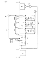
従来の制御方式のA2O法処理フローを図1に、本発明の制御方式のA2O法処理フロ−を図2に示す。
The invention method will be described using a biological phosphorus and nitrogen simultaneous removal process, particularly the A 2 O method as an example.
The A 2 O method processing flow of the conventional control method in FIG. 1, A 2 O method processing flow control method of the present invention - is shown in Figure 2.
いずれの方法も下水の処理手順は同じである。下水1に含まれる粗大浮遊物(主として汚泥)は、最初沈殿池2において沈降除去される。その後、最初沈殿池流出水3は、嫌気槽5に流入する。嫌気槽5では前述したように活性汚泥中のポリりん酸蓄積細菌がりんの吐き出しをおこなう。無酸素槽6には、好気槽7から硝化液17が循環返送される。無酸素槽6においては、この硝化液17中のNO2-N並びにNO3-Nは、活性汚泥中の脱窒細菌により、下水中の有機物との脱窒反応によって、窒素ガスとして除去される。好気槽7では、活性汚泥中の硝化細菌によりアンモニア性窒素の酸化(硝化)が行なわれる。また、好気槽7では、活性汚泥中のポリりん酸蓄積細菌が、りんを過剰に摂取する。最終沈殿池8では、活性汚泥を沈降分離し、上澄液は放流する。沈降分離された濃縮活性汚泥は、その一部を余剰汚泥として引きぬくとともに返送汚泥15として、嫌気槽5に返送ポンプ10により返送される。図1の従来法と図2の発明法では、好気槽7や嫌気槽5の運転管理方法が大きく異なっている。
Both methods have the same sewage treatment procedure. Coarse suspended solids (mainly sludge) contained in the
まず、窒素除去の視点から、本発明の中心である好気槽7の運転方法を説明する。
両法とも好気槽7では、基本として、常時、ベースノズル(ベースブロワ13に空気供給配管接続)によって曝気を行ない、アンモニア酸化細菌により、NH4−NをNO2−Nまで酸化する。続いて、亜硝酸酸化細菌により、NO2−NをNO3−Nまで酸化する。
First, from the viewpoint of nitrogen removal, an operation method of the
In both methods, the
2NH4 + + 3O2 → 2NO2 -+2H2O+4H+ -----------(8)
2NO2 - + O2 → 2NO3 - -----------(9)
2NH 4 + + 3O 2 → 2NO 2 − + 2H 2 O + 4H + ----------- (8)
2NO 2 - + O 2 → 2NO 3 - ----------- (9)
しかしながら、好気槽7の曝気の制御方法は大きく異なる。表1に従来法と発明法の比較を示し、従来法との差異を説明する。
However, the method of controlling the aeration of the
まず、図1の従来法では、好気槽7末端部に設置したDO計19の値によって、好気槽7全体の曝気量を制御する。より具体的には、硝化反応を完了させるためには好気槽7末端部に設置したDO計19の値が通常1.5mg/L以上あることが必要とされ、このDO値によって、各ベースノズルの合計曝気量、すなわち、ベースブロワ13の曝気量の総量が増減されている。
First, in the conventional method of FIG. 1, the aeration amount of the entire
この場合、好気槽7の上流側から下流側にかけて、あくまで均一の曝気である。また、従来法では好気槽7の上流側から下流側にかけて複数の区画に分割し、それぞれの区画において、曝気量を変えたり、またどの程度、硝化反応が進んでいるかは把握することは全くなされていない。一方、図2の本発明法では、好気槽7の上流側から下流側にかけて曝気量を削減するように曝気するところに特徴がある。
In this case, uniform aeration is provided from the upstream side to the downstream side of the
すなわち、好気槽7の上流側から下流側にかけての曝気量は均一ではない。言い換えれば、好気槽7を上流側から下流側にかけて曝気量を変更できる複数の区画に分割し、各区画の曝気量を上流側から下流側へ削減するものである。発明者らは、好気槽7での硝化反応は、好気槽7の微生物量ではなく、むしろ、好気槽7への酸素供給量で支配されている場合が大半であり、好気槽7の上流側での酸素供給量を増加させることによって硝化反応を上流側で促進できることを見出した。すなわち、好気槽7の上流側を微生物量(硝化細菌量)律速になる程度まで酸素供給量を増やしてやれば、上流部において硝化反応を従来法(好気槽7の上流側から下流側にかけて均一の曝気)よりも促進できるのである。好気槽7の上流部で硝化反応を促進することにより、下水の窒素の負荷変動がかなりあったとしても処理水質の維持が容易となる利点がある。
That is, the amount of aeration from the upstream side to the downstream side of the
具体的手段としては、各区画に設置されたベースノズル(各ノズルの曝気用空気の供給配管は集合して共通のベースブロワ13に接続)の曝気量を、上流側から下流側へかけて削減するようにバルブ等で調整する。 As a concrete means, the aeration amount of the base nozzles (aeration air supply pipes of each nozzle are gathered and connected to a common base blower 13) installed in each section is reduced from the upstream side to the downstream side. Adjust with a valve or the like.
その際、特に、分割した好気槽7の各区画における「硝化反応の寄与率」に沿って曝気量を削減することで、より安定してりん及び窒素を除去することが可能となる。
At that time, in particular, by reducing the amount of aeration along the “contribution rate of nitrification reaction” in each section of the divided
なお、「硝化反応の寄与率」とは、好気槽7において硝化反応が100%進行した場合、好気槽7の各区画が硝化反応をどの程度担ったかを示す数値である。ここで硝化反応100%とは、硝化液中のNH4-Nの濃度が検出限界以下となった状態である。
The “contribution rate of the nitrification reaction” is a numerical value indicating how much each section of the
すなわち、硝化反応の寄与率[%]
=(好気槽7の各区画における硝化液中のNH4-Nの濃度
/無酸素槽6から好気槽7に流入する処理液中のNH4-Nの濃度)×100
となる。
That is, contribution rate of nitrification reaction [%]
= (Concentration of NH 4 -N in the treatment solution flowing into the NH 4 -N concentration /
It becomes.
尚、本発明において、「区画」とは、好気槽を上流から下流にかけて複数段に分けて曝気し、各段毎に曝気量の制御やORPの測定を行うという、単位操作を独立して行うための区画のことであり、単位操作を独立して行うことができれば好気槽内に新たに物理的な仕切りを設ける必要性は無い。 In the present invention, the “compartment” is a unit operation in which the aerobic tank is aerated in a plurality of stages from upstream to downstream and the aeration amount is controlled and ORP measurement is performed for each stage independently. It is a section for performing, and if a unit operation can be performed independently, there is no need to newly provide a physical partition in the aerobic tank.
ベースブロワ13による好気槽7の各区画の曝気量は、例えば、ベースノズルの弁14の開度を上流側から下流側にかけて削減するように調整する。各ベースノズルにおける曝気用空気の供給量は、前記調整後は一定を保つ。ベースノズルは各区画に1つに限ったものではなく、好気槽7各区画に複数設置してもかまわない。
The aeration amount of each section of the
さらに、下水の水質・水量変動が大きく、ベースブロワ13のみでは好気槽7各区画における硝化反応の制御が困難な場合、好気槽7の上流側から下流側にかけて複数箇所に制御用ノズル(1つのノズルに対し、1つの制御用ブロワ12で対応)を設置し、この制御用ブロワ12の曝気量を該当する好気槽7各区画における硝化反応の寄与率が達成できるように制御することが好ましい。制御用ノズルは各区画に1つに限ったものではなく、好気槽7各区画に複数設置してもかまわない。
Further, when the sewage water quality and water amount fluctuation are large and it is difficult to control the nitrification reaction in each section of the
また、この際、ベースブロワ13と制御用ブロワ12の総容量は、予測される下水の時間最大のアンモニア性窒素負荷量に対応して設定すればよい。
At this time, the total capacity of the
なお、下水の時間最大のアンモニア性窒素負荷量は、下水の時間あたりの最大水量とアンモニア性窒素濃度を積算することによって得られる。ブロワの総容量は、このアンモニア性窒素負荷量を硝酸性窒素まで酸化するのに必要な酸素量から容易に求めることができる。 In addition, the maximum ammonia nitrogen load amount of sewage time is obtained by integrating the maximum water amount per hour of sewage and the ammonia nitrogen concentration. The total capacity of the blower can be easily determined from the amount of oxygen necessary to oxidize this ammonia nitrogen load to nitrate nitrogen.
好気槽7の各区画に設置した制御用ノズル(制御用ブロワ12に空気供給配管接続)の曝気量は、以下のように制御する。すなわち、好気槽7の上流側から下流側にかけて均等に分割した複数区画の末端部にORP(酸化還元電位、銀/塩化銀電極基準)計18をそれぞれ設置し、このORP計18の測定値に応じて、ORP(酸化還元電位、銀/塩化銀電極基準)計18の近傍に設置した制御用ノズルの曝気量を増減させ、所定のORP値に維持することにより、好気槽各区画の硝化寄与率を調整する。各区画のORP値は、ORP値と硝化反応の進行度の関係を予め実際の下水を用いたバッチ実験で把握し、この得られた関係によって決定する。
The aeration amount of the control nozzle (air supply piping connected to the control blower 12) installed in each section of the
さらに従来法との比較の上で、発明法の利点についてより詳細に説明する。
従来法と比べた発明法の利点は、以下の通りである。
図1の従来法では、通常、好気槽7末端のDO計19のDO値を1.5〜3.0mg/Lとなるように、好気槽7全体を均一に曝気する(非特許文献1、非特許文献2参照)。
Further, the advantages of the inventive method will be described in more detail in comparison with the conventional method.
The advantages of the inventive method over the conventional method are as follows.
In the conventional method of FIG. 1, the
しかしながら、この考え方は、下水の時間的な負荷変動がほとんどなく、また、硝化反応を好気槽で均等に行うとの前提に立っている。すなわち、好気槽7を各区画に分割したとすると各区画での硝化寄与率が等しいことを前提としている。
However, this concept is based on the premise that there is almost no temporal load fluctuation of sewage, and that the nitrification reaction is performed uniformly in an aerobic tank. In other words, assuming that the
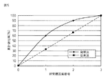
例えば、実際にはこのような管理は行なわれていないが、好気槽7を仮に上流部、中流部、下流部に3分割したとすると図5に示すように各区画の硝化寄与率は等しく33%となる。したがって、好気槽7末端のDO計19のDO値をむやみに下げることはできない。好気槽7末端のDO計19のDO値を下げすぎると、好気槽7末端部分の硝化速度が減少し、所定の硝化寄与率、ひいては所定の水質が得られなくなる。このため、好気槽7末端のDO計19のDO値は、1.5〜3.0mg/Lとせざるを得ず、省エネルギー化は困難である。
For example, although such management is not actually performed, if the
さらに、下水のアンモニア負荷が時間毎に大きく変動し上昇した場合、好気槽7の滞留時間が8〜12時間前後と長いため、流入水のアンモニア濃度が高い時間帯には、好気槽7末端部はアンモニア濃度が低い時間帯の下水を処理している場合がある。このような場合、好気槽7末端のDO計19のDO値による曝気量の制御方式では、好気槽7上流部の曝気量が不足し、好気槽7各区画での硝化速度の低下を招き、所定の硝化寄与率を得ることができなくなる。すなわち、酸素不足により各区画で想定していた安定した硝化寄与率を得ることができず、処理水質が悪化しやすい課題を有している。
Further, when the ammonia load of the sewage greatly fluctuates with time and rises, the residence time of the
一方、図2の本発明法では、従来法と比較し、以下の利点がある。
まず、発明法では、前述したように、好気槽7の上流側から下流側にかけての曝気量は均一ではない。好気槽7を上流側から下流側にかけて曝気量を変更できる複数の区画に分割し、各区画の曝気量を上流側から下流側へ削減する。すなわち、好気槽の上流側を微生物量(硝化細菌量)律速になる程度まで、酸素供給量を増やしてやれば、上流部において硝化反応を従来法(好気槽7の上流側から下流側にかけて均一の曝気)よりも促進できる。上流部で硝化反応を促進することにより、下水に窒素の負荷変動があったとしても、処理水質の維持が容易となる。
On the other hand, the method of the present invention shown in FIG. 2 has the following advantages over the conventional method.
First, in the invention method, as described above, the amount of aeration from the upstream side to the downstream side of the
発明法では、好気槽7各区画のORP計18のORP値をモニタリングし、各区画の硝化寄与率を制御しているため、例えば下水のNH4―N濃度が1.5倍に上昇しても、好気槽7の上流部で所定の硝化率を得ることには変わることがない。好気槽7の上流部で、所定の硝化率を達成できるだけの酸素量をORP計18のORP値を指標として送り込むことができるためである。
In the invention method, since the ORP value of the
ここで、留意すべきことはあらかじめアンモニアの最大の負荷量を下水水質変化の実績などから推定し、好気槽7各区画での設定のORP値に達する酸素量を送り込める、ベースブロワ13と制御用ブロワ12の総容量を設定することである。
Here, it should be noted that the maximum load of ammonia is estimated in advance from the results of changes in the quality of sewage water, and the
ベースブロワ13は、最小負荷量に設定し、制御用ブロワ12は時間最大負荷量時でも対応できるような容量に設定するのが望ましい。下水の負荷変動が大きくなればなるほど制御用ブロワ12のベースブロワ13に対する相対的な容量が大きくなり、また、負荷変動が小さくなればなるほど制御用ブロワ12の相対的な容量は小さくなる。
The
さらに、省エネルギーの視点から重要であることは、好気槽7に対して、下水の水質・水量の時間的変化に対応した各時間帯に好気槽7各区画に硝化に必要な酸素量をいかにタイムリーに無駄なく供給するかということである。
Furthermore, what is important from the viewpoint of energy saving is that the
発明法では、好気槽7各区画に、好気槽7各区画のORP値を指標として、リアルタイムで硝化に必要なだけの酸素量を供給できる。しかも、好気槽7の上流部ほど硝化寄与率を増大させ、好気槽7下流側での硝化寄与率を小さくしているため、好気槽7下流側末端のDO計19のDO値はあえて1.5mg/L以上とする必要はなく、従来法と比べて省エネルギーが可能となる。
In the invention method, an oxygen amount necessary for nitrification can be supplied to each section of the
最後に、発明法の好気槽の具体的な運転方法についてより詳細に説明する。
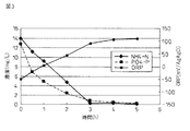
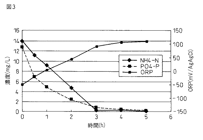
まず、図3に示すように硝化細菌が十分に存在している活性汚泥を用いて、バッチ実験を行ない硝化反応とORP値の時間的変化を求め、硝化反応とORP値の関係を予め把握する。図3の横軸は経過時間を示しているが、好気槽7における滞留時間としてとらえることができる。
Finally, the specific operation method of the aerobic tank of the inventive method will be described in more detail.
First, as shown in FIG. 3, using activated sludge in which nitrifying bacteria are sufficiently present, a batch experiment is performed to determine temporal changes in the nitrification reaction and the ORP value, and the relationship between the nitrification reaction and the ORP value is grasped in advance. . Although the horizontal axis of FIG. 3 shows the elapsed time, it can be taken as the residence time in the
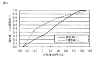
この結果から、図4に示すような好気槽におけるORP値と硝化率(各区画のNH4-N濃度/好気槽流入水中のNH4-N濃度)の関係の図を作成することができる。
したがって、図2の実機連続運転のプロセスにおいても、好気槽7に十分に硝化細菌が存在し、硝化反応が順調に進行すると、好気槽7の上流側から下流側に沿って、NH4-N が減少し、NOx-Nが増加していくと考えられる。
This result is possible to create a diagram of the relationship between the ORP value and the nitrification rate in the aerobic tank, as shown in FIG. 4 (NH 4 -N concentration of NH 4 -N concentration / aerobic tank inlet water for each partition) it can.
Therefore, even in the actual machine continuous operation process of FIG. 2, when nitrifying bacteria are sufficiently present in the
これにしたがい、好気槽7各区画のORP計18のORP値も、上流から下流にかけて徐々に上昇していくと考えることができ、バッチ実験結果と同様に、図4に示すような、好気槽7の各区画におけるORP値と硝化率の関係が判る。
Accordingly, it can be considered that the ORP value of the
図4の結果から、硝化反応とORP値の関係を予め把握する。好気槽7のORP計18のORP値が+40mV〜+60mV(銀/塩化銀電極基準)で硝化率は60〜80%、好気槽7のORP計18のORP値が+60mV〜+80mVで硝化率は80〜90%、好気槽7のORP計18のORP値が+80mV〜+100mVで硝化率は90%〜100%となった。
From the result of FIG. 4, the relationship between the nitrification reaction and the ORP value is grasped in advance. ORP value of
この結果から、好気槽7の上流側から下流側に沿って設置した好気槽7各区画のORP計18のORP値をモニタリングすることにより、各区画での硝化反応の進行度、すなわち、NH4-N の酸化の程度を知ることが可能となる。また、このような結果から、好気槽7の各区画における硝化反応の寄与率を決定することが可能となる。
From this result, by monitoring the ORP value of the
発明者らは、好気槽7各区画の最適な硝化寄与率を、実験的な検討から、以下のような分割に決定した。
発明者らは、好気槽7を均等に3分割した下水処理実験を実施し、上流部の硝化寄与率は60%程度、中流部の硝化寄与率は30%程度、下流部の硝化寄与率は10%程度が水質安定化と省エネルギー化の視点から最も望ましい管理手段であることを知見した。発明法と従来法の硝化寄与率の比較図を図5に示す。
The inventors determined the optimum nitrification contribution rate of each section of the
The inventors conducted a sewage treatment experiment in which the
発明法のように硝化寄与率を上流部に重く配分すれば、下水の負荷変動があっても水質への影響が小さく、しかも、省エネルギー運転が可能である。好気槽7の分割は、3分割に限ったものではなく、本実験結果の図5をベースとして、好気槽7を2〜5分割した場合のそれぞれの区画の硝化寄与率を決めればよい。
If the nitrification contribution rate is heavily distributed to the upstream portion as in the invention method, the influence on the water quality is small even if there is a sewage load fluctuation, and energy-saving operation is possible. The division of the
例えば、2区画分割の場合は、図5の結果から、上流部の硝化寄与率は75%程度、また、下流部の硝化寄与率は25%程度が望ましいことがわかる。また、この場合には図4から、上流部のORP計18のORP値は、+50mV〜+60mV(銀/塩化銀電極基準)、また下流部のORP計18のORP値は、+80mV〜+100mV(銀/塩化銀電極基準)に制御すればよい。
For example, in the case of two-part division, it can be seen from the results of FIG. 5 that the nitrification contribution rate in the upstream portion is preferably about 75% and the nitrification contribution rate in the downstream portion is preferably about 25%. In this case, from FIG. 4, the ORP value of the
また、4区画分割の場合は、図5の結果から、1段部の硝化寄与率は50%2段部の硝化寄与率は25%、3段部の硝化寄与率は20%、4段部は5%が望ましい。この場合には図4から、1段部のORP計18のORP値は、+20mV〜+30mV(銀/塩化銀電極基準)、2段部のORP計18のORP値は、+50mV〜+60mV(銀/塩化銀電極基準)、3段部のORP計18のORP値は、+80mV〜+90mV(銀/塩化銀電極基準)、また、4段部のORP計18のORP値は、+90mV〜+100mV(銀/塩化銀電極基準)に制御すればよい。
In the case of 4 divisions, from the results shown in FIG. 5, the nitrification contribution ratio of the first stage is 50%, the nitrification contribution ratio of the second stage is 25%, the nitrification contribution ratio of the third stage is 20%, and the fourth stage. 5% is desirable. In this case, from FIG. 4, the ORP value of the
さらに、5区画の分割の場合も図5から好気槽を5区画にわけて上述のように決定すればよい。 Furthermore, in the case of dividing into five sections, the aerobic tank may be divided into five sections from FIG. 5 and determined as described above.
省エネルギーの観点から重要なことは、最下流の好気槽区画での硝化寄与率を小さくすることである。最下流の好気槽区画での硝化寄与率を小さく設定すれば、最下流の好気槽末端部のDOを1.5mg/L以上にあえて維持しなくても、完全硝化が容易に進むため、省エネルギー化を達成することができる。この場合、前記好気槽の分割区画数2以上5以下のいずれの場合でも、当該分割した最下流区画のORP値は+80mV以上+100mV以下の範囲に含まれる。 From the viewpoint of energy saving, it is important to reduce the contribution of nitrification in the most downstream aerobic tank compartment. If the contribution of nitrification in the downstream aerobic tank compartment is set small, complete nitrification will proceed easily even if DO at the end of the downstream aerobic tank is not maintained at 1.5 mg / L or more. , Energy saving can be achieved. In this case, in any case where the number of divided sections of the aerobic tank is 2 or more and 5 or less, the ORP value of the divided most downstream section is included in the range of +80 mV or more and +100 mV or less.
しかしながら、DOを用いる従来法では、好気槽7を分割した各区画の硝化反応の進行度を知ることはできない。また、DOはあくまで硝化反応を進めるための必要条件の1つであるため、硝化反応の進行度とは直接の関係はない。例えば、DO値がほぼ0mg/Lであっても、硝化反応が進んでいる場合と全く硝化に必要な酸素量が不足し、硝化反応が進んでいない場合がある。前者は硝化に必要な酸素は供給しているが、酸素消費とのバランスでほぼ0となっている場合であり、後者は硝化に必要な酸素が不足している場合である。このような区別はDO値によって得ることはできない。したがって、DOのみの管理の場合、硝化の進行度を知ることはできない。
However, in the conventional method using DO, it is impossible to know the progress of nitrification reaction in each section into which the
次に、好気槽7でのベースブロワ13、制御用ブロワ12の設置方法、運転方法について詳細に説明する。好気槽7を多く分割すればするほどより詳細な好気槽7の硝化反応の制御が可能となる。しかしながら、一方で、制御機器やブロワの数が増大する為、好気槽7の分割数は5分割以下とするのが現実的である。2分割でもある程度の効果をうることができる。
Next, the installation method and operation method of the
事例として、以下に、好気槽7を3分割した事例を述べる。好気槽7を3分割し、前述したようにそれぞれの硝化寄与率を60%、30%、10%と設定する。これは発明者らが実施した実験結果では、好気槽を上流側から下流側に向かって3分割した場合、上流の好気槽で硝化寄与率が60%、中流の好気槽での硝化寄与率が30%、下流の好気槽で硝化率が10%となるように、好気槽の上流側から下流側に向けて各区画に設置した制御用ノズル(制御用ブロワ12に空気供給配管接続)の曝気量を制御した場合、最も処理水質の安定性維持と省エネルギー化を達成することができたためである。
As an example, a case where the
ベースブロワ13からの好気槽7各区画への曝気量は、制御用バルブ14によってあらかじめ手動又は自動で調整し、好気槽7の各区画で設定した硝化寄与率に沿う形で、換言すれば、1gのNH4-Nを酸化するためには4.57gの酸素が必要であるが、各区画に必要なこの酸素量に見合う形で、制御用バルブ14によってあらかじめ手動又は自動で調整し、上流部から下流部へ削減する。具体的には、ベースブロワ13からの各区画への曝気量は、硝化寄与率に連動させ、例えば、好気槽7上流部で60%、中流部で30%、下流部で10%の空気供給量比なるように調整すればよい。ただし、反応効率は、ノズルの種類によって異なるので、実際の空気供給量は、用いるノズルの酸素吸収効率データをもとに算出すればよい。
In other words, the amount of aeration from the
さらに、好気槽7の各区画への曝気量は、ORP値によってフィードバック制御することが好ましい。
Furthermore, it is preferable that the amount of aeration to each section of the
例えば、好気槽7の上流側末端部のORP計18の設定値を+40mV以上〜+42mV以下、好気槽7の中流部の末端部のORP計18の設定値を+60mV以上〜+62mV以下、好気槽7の下流部の末端部のORP計18の設定値を+90mV以上〜+92mV以下となるように、制御用バルブ14の調整、あるいは制御用ブロワ12のブロワ回転数を自動制御することによって曝気量をORP値によって制御する。制御用バルブ14により制御用ブロワ12の曝気量を制御する場合、ORP値の制御幅の設定は、1mV以上2mV以下とすることが望ましい。2mV超であれば、ORP値が上昇する速度とDO値が上昇する速度にかなり差があるため、DO値が上昇しやすくなり不経済となる。また、ORP値の1mV未満の場合は、制御用バルブ14が煩雑に稼動し、故障を招きやすくなる。
For example, the set value of the
このような本発明法の発想は従来の方法からは全く読み取れない。また、脱窒素促進の視点から考えると、好気槽7末端から硝化液16を無酸素槽6へ送水しているが、好気槽7末端でのDO計19のDO値が高すぎると、無酸素槽6での脱窒反応が阻害を受ける。本発明法では、好気槽7末端のDO計19のDO値を低めに保つことができ、脱窒素の観点からも本発明法は極めて望ましいことである。
Such an idea of the method of the present invention cannot be read at all from the conventional method. From the viewpoint of promoting denitrification, the
ただし、このようなORPによる硝化反応の制御法は、活性汚泥中に硝化細菌が十分に存在していることが前提である。活性汚泥中の硝化細菌量が非常に小さい場合などには適用できないことは留意しておく必要がある。このような場合の反応槽のORP値は、必ずしもアンモニアの酸化反応を示していない。また、ORP値は、pH、水温の影響を受けるため、大幅に変動する場合は設定値の補正を必要とする場合がある。 However, such a method for controlling the nitrification reaction by ORP is based on the premise that nitrifying bacteria are sufficiently present in the activated sludge. It should be noted that this method cannot be applied when the amount of nitrifying bacteria in the activated sludge is very small. The ORP value of the reaction tank in such a case does not necessarily indicate the oxidation reaction of ammonia. Further, since the ORP value is affected by the pH and the water temperature, the set value may need to be corrected if it greatly fluctuates.
次に、りん除去の視点から本発明の好気槽の運転方法を説明する。
まず、好気槽7においてりんの摂取に着目した場合について、図2を用いて説明する。
好気槽7では、ポリリン酸蓄積細菌により、りんが過剰に摂取される。従来、好気槽7でのりんの過剰摂取について、DO濃度との関連が多く指摘されて、概ね、好気槽7末端のDO濃度が1.5〜3.0mg/Lが望ましいとされてきた(非特許文献1、非特許文献2参照)。この条件は、先に述べた従来法での硝化反応の管理条件と一致している。これに対して、発明者らは、好気槽7のORP18とりんの摂取率が密接な関係があることを見出した。
Next, the operation method of the aerobic tank of the present invention will be described from the viewpoint of phosphorus removal.
First, the case where attention is paid to the intake of phosphorus in the
In the
図3に示すようにポリリン酸蓄積細菌が十分に存在している活性汚泥を用いて、バッチ実験を行ない、りん摂取反応とORP値の時間的変化を求め、りん摂取反応とORP値の関係を予め把握した。図3の横軸は経過時間を示しているが、好気槽7における滞留時間としてとらえることができる。したがって、好気槽7に十分にポリリン酸蓄積細菌が存在し、ポリリン酸蓄積細菌によるりん摂取反応が順調に進行すると、好気槽7の上流側から下流側に沿って、PO4-Pが減少 していくにしたがい、好気槽7各区画のORP計18のORP値も、上流から下流にかけて徐々に上昇していくと考えることができる。
As shown in Fig. 3, a batch experiment was conducted using activated sludge with sufficient polyphosphate-accumulating bacteria to determine the temporal change in the phosphorus intake response and the ORP value, and the relationship between the phosphorus intake response and the ORP value was determined. I grasped it beforehand. Although the horizontal axis of FIG. 3 shows the elapsed time, it can be taken as the residence time in the
この結果から、図4に示すような好気槽におけるORP値とPO4-P摂取率(各区画のPO4−P濃度/好気槽7流入水中のPO4−P濃度)の関係の図を作成することができる。したがって、図2の実機連続運転のプロセスにおいても、好気槽7に十分にポリリン酸蓄積細菌が存在し、PO4-P摂取反応が順調に進行すると、好気槽7の上流側から下流側に沿って、PO4−Pが減少していくと考えられる。
From this result, Fig relationship ORP value and PO 4 -P uptake (PO 4 -P concentration of PO 4 -P concentration /
これにしたがい、好気槽7各区画のORP計18のORP値も、上流から下流にかけて徐々に上昇していくと考えることができ、バッチ実験結果と同様に、図4に示すような、好気槽7の各区画におけるORP値とPO4-P摂取率の関係が判る。
Accordingly, it can be considered that the ORP value of the
この結果から、りん摂取反応とORP値の関係を予め把握する。好気槽7のORP計18のORP値が+40mV〜+50mV(銀/塩化銀電極基準)でりん摂取率は80%前後、好気槽7のORP計18のORP値が+60mV〜+70mVでりん摂取率は85%前後、好気槽7下のORP計18のORP値が+80mV〜+100mVでりん摂取率は90%〜95%と推定される。つまり、好気槽7の上流側から下流側に沿って、好気槽7各区画のORP計18のORP値をモニタリングすることにより、りんの摂取の程度を知ることが可能となるのである。
From this result, the relationship between the phosphorus intake response and the ORP value is grasped in advance. The ORP value of the
さらに、この場合、りんの摂取は硝化反応に先行して生じることもわかった。したがって、りんと窒素の除去を同時に進める場合には、好気槽7での硝化反応の進行を管理しておけば、りんの摂取反応の進行も問題ないと考えられる。
Furthermore, in this case, it was also found that the intake of phosphorus occurs prior to the nitrification reaction. Therefore, when removing phosphorus and nitrogen at the same time, if the progress of the nitrification reaction in the
一方、従来法では、好気槽7各区画におけるりん摂取の進行度を知ることはできない。例えば、DOはあくまでりんの摂取反応を進めるための必要条件の1つであって、りんの摂取反応の進行度とは直接の関係はない。例えば、DO値が0mg/Lであっても、りん摂取反応が進んだ結果である場合とりん摂取に必要な酸素量が不足している場合がある。このような区別はDO値によって得ることはできない。
On the other hand, in the conventional method, it is not possible to know the progress of phosphorus intake in each section of the
したがって、窒素除去と同様、好気槽7の各区画のORP値によって、好気槽7各区画への曝気量を制御することにより、りんの摂取反応を管理することが可能であると考えられる。
Therefore, similarly to nitrogen removal, it is considered that the intake reaction of phosphorus can be managed by controlling the amount of aeration to each section of the
ただし、りん摂取の場合は、後述するが、嫌気槽5でのりんの放出が十分に生じていることが前提である。嫌気槽5でのりんの放出が十分に生じていない場合には、りん摂取反応自体が生じない(りん蓄積細菌が少ない)ため、ORP値によってその進行の程度を予測することはできない。このような場合には、好気槽7の各区画のORP値が上昇したとしても硝化の進行を示しているにすぎなくなる。
However, in the case of phosphorus intake, as will be described later, it is premised that phosphorus is sufficiently released in the
続いて、りん除去の視点から、発明法の嫌気槽5の運転について説明する。
嫌気槽5は、以下のようにORPを用いて制御する。
Next, the operation of the
The
生物学的りん除去を行なうポリリン酸蓄積細菌は、好気条件下で吸収したPO4-Pを細胞内でポリリン酸の顆粒として保持しており、嫌気槽5においては、この顆粒のポリリン酸を加水分解して、PO4-Pとして放出するとともに、下水中の有機物、特に有機酸や発酵産物を細胞内に摂取する。PO4-Pの放出速度は、基質の種類や濃度によって大きく異なっており、酢酸などの有機酸が基質である場合にPO4-Pの放出速度が大きいとされている。細胞内に摂取された有機物は、グリコーゲンやPHB(ポリハイドロブチレイト)の高分子物質の形で貯蔵される。これらの細胞内物質は、再び好気条件下に置かれると、酸化分解され減少するが、ポリリン酸蓄積細菌はこの基質利用により増殖していく。また、この際に、ポリリン酸蓄積細菌は、PO4-Pを通常の活性汚泥(BOD除去を目的とし、好気条件のみで運転されている活性汚泥)と比較して過剰に摂取し、過剰に摂取したPO4-Pを細胞内でポリリン酸の顆粒として保持する。
The polyphosphate-accumulating bacterium that performs biological phosphorus removal retains PO 4 -P absorbed under aerobic conditions as granules of polyphosphate in the cells. In the
このような生物学的りん除去を行なうポリリン酸蓄積細菌の反応を促進する上で重要なことは、嫌気槽5において、有機酸や発酵産物が存在することである。しかしながら、実際の処理設備では、雨水や返送汚泥の影響により、嫌気槽5にNOx−NやDOが流入する場合がしばしばある。嫌気槽5において、NOx−N又はDOが存在すると、有機酸は直ちに分解されてしまう。以下に、有機酸として、酢酸を用いた場合の反応を示す。
What is important in promoting the reaction of polyphosphate-accumulating bacteria that perform such biological phosphorus removal is the presence of organic acids and fermentation products in the
8NO3 - + 5CH3COOH → 4N2+10CO2+6H2O+8OH- ------------(5)
8NO2 - + 3CH3COOH → 4N2+6CO2+4H2O+8OH- ------------(6)
2O2 + CH3COOH → 2CO2+2H2O ------------(7)
8NO 3 - + 5CH 3 COOH →
8NO 2 - + 3CH 3 COOH →
2O 2 + CH 3 COOH → 2CO 2 + 2H 2 O ------------ (7)
これから、例えば、NO3−Nが1mg/L存在すると、これに伴い、酢酸2.7mg/Lが消費されることとなる。また、NO2−Nが1mg/L存在すると、これに伴い、酢酸1.6mg/Lが消費されることとなる。一方、DOは1mg/L存在すると、これに伴い、酢酸0.9mg/Lが消費されることとなる。この結果から、特に、NO3−Nの存在が酢酸の消費に及ぼす影響が極めて大きいことがわかる。NO3−N、NO2−N、及びDOは、調査の結果、雨水が混入する下水1や返送汚泥8中にも存在する場合がたびたびあるが、特に、好気槽7の運転条件(高DO値、高ORP値運転)によっては、最終沈殿池8から嫌気槽5に返送される返送汚泥15中に高濃度のNO3−Nが存在することがあり、この場合、嫌気槽5においてりんの放出が極めて生じにくくなる。例えば、流入下水の酢酸濃度が20mg/Lあったとしても、NO3−Nを10mg/L含む返送汚泥が下水に対して50V/V%混入すると、NO3−N が13.5mg/Lの酢酸を消費してしまう。
From this, for example, when NO 3 —N is present at 1 mg / L, acetic acid 2.7 mg / L is consumed accordingly. Further, when NO 2 -N is present at 1 mg / L, acetic acid 1.6 mg / L is consumed accordingly. On the other hand, if 1 mg / L of DO is present, acetic acid 0.9 mg / L is consumed accordingly. From this result, it can be seen that the influence of NO 3 -N on the consumption of acetic acid is extremely large. As a result of investigation, NO 3 -N, NO 2 -N, and DO are often present in
また、下水中あるいは返送汚泥中のNOx−NやDOによる有機酸の消費ばかりでなく、装置特性(脱窒槽からの逆流など)も影響する場合がある。したがって、下水中の有機酸濃度のみで、嫌気槽5でのりんの放出を判断するのは難しく、また、この嫌気槽5でのりんの吐き出しに関与する要因(有機酸、NOx−N、DO、装置特性など)を、すべて事前に把握して有機酸4の添加量を制御することは困難と考えられる。
In addition, not only the consumption of organic acids by NO x -N or DO in sewage or return sludge, but also device characteristics (such as backflow from the denitrification tank) may affect. Therefore, it is difficult to judge the release of phosphorus in the
そこで、発明者らは嫌気槽5のORP計18のORP値による制御による有機酸4を添加する方法を発案した。具体的には、嫌気槽5のORP計18のORP値を−200mV以下−400mV以上に維持、より好ましくはORP計18のORP値の測定累積頻度の50%以上が−250mV以下−350mV以上に維持されるように有機酸4を嫌気槽5に添加する方法を開発している。累積頻度の採取頻度は、1分から10分毎にデータを毎日採取し、これをデータ解析し、一定期間、例えば1日あたりのORP値の累積頻度を算出する。ORP制御による有機酸4の添加の具体的方法の1例を示すと、嫌気槽5のORP計18のORP値が−250mV以上になると、有機酸4を嫌気槽5に添加し、嫌気槽5のORP計18のORP値が−260mVになると停止させることにより、嫌気槽5のORP計18のORP値を−200mV以上−400mV以下内に納まるように運転する。
Therefore, the inventors have devised a method of adding the
図1の従来法では、有機酸4の添加がない為、嫌気槽5のORP計18のORP値が降雨期に上昇し易く、又、大きくばらつき、りんの放出も小さくなった。しかしながら、図2の発明法では、嫌気槽5のORP計18のORP値が−260mV以下となり、又りんの放出量が大きくなった。酢酸4を嫌気槽5に添加すると嫌気槽5のORP計18のORP値を低く保ち、りんの放出量が大きくする事ができる。これは酢酸の添加によってNOx-Nの阻害を除去できるためと考えられる。
In the conventional method shown in FIG. 1, since the
また、嫌気槽5の滞留時間を増大させることもりん放出促進に効果がある。
図13に酢酸濃度の異なる下水と嫌気槽におけるりん放出濃度の関係を示す。この結果から下水中の酢酸濃度が低い場合には、りん放出濃度も低いことがわかる。しかしながら、このような場合でも嫌気槽5の滞留時間を長くとれば、高いりん放出濃度を得ることができる。例えば、りん放出濃度10mg/Lを目安とすると、酢酸濃度が6から8mg/Lの場合は、嫌気槽の滞留時間が1.5時間程度で十分であるが、酢酸濃度が3mg/Lの場合は5時間必要となる。従来、嫌気槽の滞留時間は1.5〜2.0時間とされてきたが、このように、従来のままでは下水の種類によっては滞留時間が足らない場合がある。
Further, increasing the residence time of the
FIG. 13 shows the relationship between the sewage with different acetic acid concentrations and the phosphorus release concentration in the anaerobic tank. This result shows that when the concentration of acetic acid in the sewage is low, the phosphorus release concentration is also low. However, even in such a case, if the residence time of the
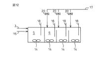
嫌気槽5の滞留時間を増加させ、りん放出濃度を増加させる方法として以下のような方法が考えられる。図12にこの1例を示す。
The following method can be considered as a method of increasing the residence time of the
すなわち、無酸素槽6を2段以上5段以下に分割し、嫌気槽5のORP計18のORP値を指標として、硝化液17を投入する無酸素槽6の位置を変更するのである。分割数が多いほど、より詳細な制御が可能であるが、制御機器や攪拌機の数が増大する為、無酸素槽6の分割数は5分割以下とするのが現実的である。無酸素槽6の添加位置は配管などのバルブを操作することにより変更する構造とすればよい。この方法により無酸素槽の一部を嫌気槽とし、嫌気槽でのりん放出濃度が10mg/L程度となるように嫌気槽の滞留時間を調整することが可能となる。
That is, the oxygen-
もちろん、計画段階で下水の酢酸濃度が低いことが明らかな場合は、嫌気槽5の滞留時間を従来よりも長く設定してもかまわない。
Of course, when it is clear that the concentration of acetic acid in the sewage is low at the planning stage, the residence time in the
続いて発明法における無酸素槽6の運転方法について説明する。
無酸素槽6では、好気槽7で生成したNO2−N及びNO3−Nを含む硝化液17を無酸素槽6に循環ポンプ16を用いて循環し、最初沈澱池流出水3中の有機物(BOD)を用いて硝化液17中のNO2−N及びNO3−Nを窒素ガスまで還元する。
Next, an operation method of the
In the
上流に嫌気槽5がある場合、下水中の一部の有機物(BOD)成分、例えば有機酸は、嫌気槽5においてポリリン酸蓄積細菌による取りこみで減少するので、残留BOD成分を用いて、脱窒反応を行なう。この残留BOD成分の測定は、活性汚泥に吸着されているものがかなりあり、測定は困難である。硝化液17の循環量は、下水1の流入量に対して、通常100〜200V/V%で設定する。この場合、理論窒素除去率は、以下の式で表される。
When there is an
E=R/(1+R)
ここに、E:理論窒素除去率(-) ; R:硝化液循環比(-)
E = R / (1 + R)
Where E: theoretical nitrogen removal rate (-); R: nitrification liquid circulation ratio (-)
実際には硝化液循環量は200V/V%までは窒素除去率が向上するが、これ以上増加させても窒素除去率を向上させることは難しい。これは、硝化液循環量を増やしても、無酸素槽5での有機物/窒素比が低下したり、硝化液17中のDOの持ち込み量が増え、脱窒阻害が生じやすいためである。無酸素槽5での脱窒反応が低下し、NOx-Nが残留するとORP計18のORP値が上昇する。例えば、ORP計18のORP値が−150mV以下ではNOx-N濃度は0.5mg/L以下であるが、ORP計18のORP値が−100mVを越えるとNOx-N濃度は2.0mg/Lをオーバーする。この結果から、無酸素槽5のORP計18のORP値は、−200mV以上−100mV以下であることが望ましい。本発明では、従来法と違い好気槽7末端のDO計18のDO値を低く保つことができるため、無酸素槽5のORP計18のORP値を−200mV以上−100mV以下に維持することができる。
Actually, the nitrogen removal rate is improved up to 200 V / V% of the nitrification solution circulation amount, but it is difficult to improve the nitrogen removal rate even if it is further increased. This is because even if the nitrifying solution circulation rate is increased, the organic matter / nitrogen ratio in the
無酸素槽5での脱窒反応がどうしても低下しやすい場合には、無酸素槽5のORP計18のORP値を指標として、ORP計18のORP値は、−200mV以上−100mV以下となるように、有機酸4を添加してもかまわない。
If the denitrification reaction in the oxygen-
最終沈殿池8では、活性汚泥の沈降分離を行なう。通常、水面積負荷が20〜25m3/m2・日程度、有効水深3.5〜4.0mで設計されるが、これに準ずればよい。最後に、本制御に用いるORP計18について説明する。
In the
今回の発明は、主たる制御をORPで行うため、この管理が非常に重要となる。特に設置数が増加するので、維持管理を容易とするため、できる限り自動化することが望ましい。ORP計18は、図11に示すように電極の先端部に設置したノズルにより空気を噴霧する空気洗浄方式で、定期的に洗浄することが望ましい。洗浄を行わない場合、電極部に汚れが付着しやすく、数値の信頼性が徐々に低下する。また、ブラシなどによる自動洗浄は、毛髪などの影響を受けやすい。空気洗浄は、毛髪などの影響を受けず、長期間使用でき、かつ、洗浄間隔を工夫することにより嫌気槽5、無酸素槽6、好気槽7のいずれでも使用可能である。
In the present invention, since the main control is performed by ORP, this management is very important. In particular, since the number of installations increases, it is desirable to automate as much as possible in order to facilitate maintenance. It is desirable that the
例えば、ORP計18の1回当りの空気洗浄時間を3秒以下とすることで、嫌気槽5でのDO値の影響と洗浄に伴うORP18の変化を最小限とし、処理に影響を与えないようにできる。
For example, by setting the
例えば、洗浄間隔を1時間に1回、0.3MPaの空気圧で洗浄時間を0.3秒とした場合のORP値18の変化は、5〜10mV程度の上昇であり、かつORP値の回復は10分程度であるため、1時間に1回の洗浄を実施しても嫌気槽を制御する上では何ら問題はない。また、洗浄直後の嫌気槽5のDO18は0.0mg/Lで変化はなく、りん除去への影響もない。
For example, when the cleaning interval is once an hour, the cleaning time is 0.3 seconds with an air pressure of 0.3 MPa, the change in the
表2には1回当りのエア洗浄時間を変更した場合のORP値の変動幅の一例を示す。1回当りの洗浄時間が3秒以下の場合は、ORP値の上昇幅が小さく、回復までの時間も20分以下であるが、3秒を越えると上昇幅及び回復までの時間が長くなり、処理に影響を与える傾向にある。よって、洗浄時間は、0超〜3秒以下とした。 Table 2 shows an example of the fluctuation range of the ORP value when the air cleaning time per change is changed. When the cleaning time per time is 3 seconds or less, the increase range of the ORP value is small and the time to recovery is 20 minutes or less, but when it exceeds 3 seconds, the increase range and the time to recovery become long, It tends to affect processing. Therefore, the cleaning time is set to more than 0 to 3 seconds or less.
洗浄時間は短いほどORPの変化幅を小さくできるため、出来うる限り短くするのが好ましいが、洗浄効果との兼ね合いから適宜時間と間隔は選定する。また、洗浄空気の圧力は0.05〜0.5Mpaであれば影響は無視できる。 The shorter the cleaning time, the smaller the range of change in ORP, so it is preferable to make it as short as possible. However, the time and interval are appropriately selected in consideration of the cleaning effect. In addition, if the pressure of the cleaning air is 0.05 to 0.5 MPa, the influence can be ignored.
以下、本発明の実施例を説明する。なお、本発明は本実施例に限定されるものではない。 Examples of the present invention will be described below. In addition, this invention is not limited to a present Example.
実施例1:都市下水処理への適用
本発明の方法を都市下水処理へ適用し、図2に示したA2O法のパイロットプラントによってORP制御効果を検証した。本装置は、嫌気槽5(容量:2.5 m3)、脱窒槽6(容量:2.5 m3)、好気槽7(容量:2.5 m3×3分割)、沈殿槽8(容量:5.7 m3)から構成される。
Example 1 Application to Municipal Sewage Treatment The method of the present invention was applied to municipal sewage treatment, and the ORP control effect was verified by the pilot plant of the A 2 O method shown in FIG. This apparatus has an anaerobic tank 5 (capacity: 2.5 m 3 ), a denitrification tank 6 (capacity: 2.5 m 3 ), an aerobic tank 7 (capacity: 2.5 m 3 × 3 divided), and a sedimentation tank 8 (capacity: 5.7 m 3). ).
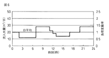
都市下水を主体とする分流式の下水処理場(現有処理能力26,000 m3/d)の最初沈澱池流出水3を実験原水として、図6に示すように時間変動を与え、(最大28m3/d;基準20m3/d;最小12m3/d)供給した。本条件での反応槽の総HRT(反応槽の容積/最初沈澱池流出水供給速度)は基準水量時で15時間(嫌気槽:3h;脱窒槽:3h;好気槽:9h)である。最大水量時には、総HRTは11時間となる(嫌気槽:2.2h;脱窒槽:2.2h;好気槽:6.6h)。最小水量時には、総HRTは25時間となる(嫌気槽:5h;脱窒槽:5h;好気槽:15h)。汚泥返送率は下水1の供給量の50%、硝化液17の循環量は下水1の供給量の150%とした。
Using the first
各槽のORP制御は以下のように行った。
まず、嫌気槽5は、ORP計18のORP値が制御値(−260mV)以上になった場合に、酢酸4を30mg/L-下水を添加する制御とした。しかし、後述するような好気槽7の運転を行った結果、嫌気槽5のORP計18のORP値は、−300mVから−350mVで推移した。このため、嫌気槽5には酢酸4の添加は必要でなかった。
The ORP control of each tank was performed as follows.
First, the
無酸素槽6には硝化液17が循環される。ORP計18による制御は特に実施しなかった。
さらに、好気槽7は以下のように運転した。
A nitrifying
Further, the
好気槽7は、図5の結果から、好気槽7を3分割した場合、上流部の硝化寄与率は60%程度、中流部の硝化寄与率は30%程度、下流部の硝化寄与率は10%程度が水質安定化と省エネルギー化の視点から望ましい管理数段であることを知見しているので、好気槽7(上流部A〜中流部B〜下流部Cそれぞれの区画での硝化寄与率を60%、30%、10%と設定した。また、硝化寄与率により、好気槽7(上流部A〜中流部B〜下流部C)の空気量は、上流部Aで120L/分、中流部Bで60L/分、下流部Cで20L/分とした。
From the results shown in FIG. 5, the
また、ORP計18のORP値が設定値以下になると制御ブロワ12を作動させて空気量(70L/分;上流部A、中流部B、下流部C)を増加させ、ORP計18のORP値を設定値以上に維持するようにフィードバック制御で運転した。
When the ORP value of the
ここで、好気槽7の各区画末端部に設置したORP計18のORPの制御設定値は、予め実施したORP値と硝化率との関係から、好気槽7の上流部Aで+40〜+42mV、好気槽7の中流部Bで+60〜+62mV、好気槽7の下流部Cで+90〜+92mVとした。なお、上述したように脱窒槽6ではORP計18による制御は行わず、ORP計18のORP値は測定・記録のみとした。
Here, the ORP control setting value of the
また、嫌気槽5、無酸素槽6、好気槽7のいずれのORP計18も、図11に示すように電極の先端部に設置したノズルにより空気を噴霧する空気洗浄方式とし、1時間に1回自動洗浄した。ORP計18の1回当りの空気洗浄時間は3秒以下とした。空気洗浄間隔を1時間に1回、0.3MPaの空気圧で洗浄時間を0.3秒とした場合のORP値の変化は、5〜10mV程度の上昇であり、かつORP値の回復は10分程度であるため、1時間に1回の洗浄を実施しても嫌気槽を制御する上では何ら問題はなかった。また、りん除去への影響も後述するように認められなかった。
Further, the
各反応槽のMLSSは2000〜3000mg/Lに維持した。また、A-SRT(好気槽7での汚泥滞留時間)は12〜13日で管理した。 MLSS of each reaction tank was maintained at 2000 to 3000 mg / L. Moreover, A-SRT (sludge residence time in the aerobic tank 7) was managed in 12 to 13 days.
最初沈殿池流出水3のNH4-N濃度は、夜間が低く(9〜12mg/L)、午前中に急激に増加し、12時頃がピークとなった(20〜30mg/L)。また、最初沈殿池流出水3のPO4-P濃度も、深夜に低く(2.1〜2.2 mg/L)、午前中に増加し、8-11時頃がピークとなった(3.0〜3.5 mg/L)。このように最初沈殿池流出水3の水量、水質ともに、大幅に時間変動する条件下で窒素、りん処理の安定性を評価した。
The NH 4 —N concentration in the first
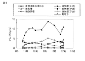
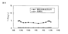
まず、発明法によるりんの除去状況を説明する。
図7に最初沈殿池流出水3および各槽ならびに処理水9のPO4-Pの経時変化を示す。また、図8に最初沈殿池流出水3および処理水9のT-P(全りん)の経時変化を示す。発明法では、嫌気槽5のORP18は、−300mVから−350mVで推移し、嫌気槽5でのりん放出は、4〜14mg/Lの範囲で推移した。嫌気槽5でのりんの放出が多い場合であっても、好気槽7において十分なりんの摂取が生じ、処理水のPO4-Pはいずれの時間帯においても0.1mg/L以下と安定していた。この結果、処理水のT-Pもいずれの時間帯においても0.2mg/L程以下で安定し、処理目標の0.5mg/L以下を達成していた。
First, the phosphorus removal status according to the invention method will be described.
FIG. 7 shows time-dependent changes in PO 4 -P in the first
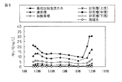
次に、発明法による窒素の除去状況を説明する。
図9に最初沈殿池流出水3および各槽ならびに処理水9のNH4-Nの経時変化を示す。また、図10に最初沈殿池流出水3および各処理水9のT-N(全窒素)の経時変化を示す。好気槽7流入水のNH4-Nは4.8mg/Lであったが、好気槽7のNH4-Nは、上流部(ORP=+40〜+42mV制御)で平均1.8 mg/L、中流部(ORP値+60〜+62mV制御)で平均0.5mg/L、下流部(ORP値+90〜+92mV制御)で0.1mg/L以下となっており、いずれの時間帯においても硝化反応は十分に進んでいた。また、表3に示すように好気槽7各区画において所定の硝化寄与率を得ることができた。
Next, the state of nitrogen removal by the inventive method will be described.
FIG. 9 shows the changes over time of NH 4 -N in the first
また、無酸素槽5では、好気槽7から循環されてくる硝化液17中のNO2−N及びNO3−Nを、最初沈殿池流出水3中のBODで表示される有機物を用いて除去する。好気槽7から循環される硝化液17は、DOをほとんど含んでいないため、無酸素槽5のORP計18のORP値は、−200mV以上−150mV以下で推移した。この結果、無酸素槽5での脱窒素反応も進行した。処理水のT-Nは、6から10mg/Lで推移し、処理目標の10mg/L以下を達成していた。
In the
最後に、DOの削減効果について説明する。
好気槽7のORP制御を行った結果、好気槽7下流部のDO計19のDO値は、0〜1.2mg/Lの範囲で時間的に推移していた。このように好気槽7は従来法(DO値;1.5〜.2mg/L以上)と比べてかなり低いDO値の条件であったが、窒素、りんの除去に問題は全く生じなかった。好気槽7下流部のORP計18のORP値が+90mVに維持されていれば、硝化反応はほぼ完全に進行しており、かつ、りん摂取反応も十分に行われていた。このように発明法では従来法と比べて、好気槽7下流部のDO値をかなり下げて運転することが可能となり、曝気エネルギーを削減することにより、省エネルギー化が図れる。
Finally, the DO reduction effect will be described.
As a result of ORP control of the
表4に、24時間のコンポジットデータ(2時間毎に採取した1日の平均水質)を示す。各項目の分析方法は、工場排水試験方法(JISK0102)に準拠した。この結果、発明法では、最初沈殿池流出水3の水量、水質の大幅な時間的変動があっても、処理水質は極めて安定していることが明らかになった。
Table 4 shows 24 hour composite data (average water quality per day collected every 2 hours). The analysis method of each item was based on the factory drainage test method (JISK0102). As a result, it became clear that the quality of the treated water was extremely stable in the invention method even when the amount of water and the quality of the first
1 下水
2 最初沈殿池
3 最初沈殿池流出水
4 酢酸添加装置
5 嫌気槽
6 無酸素槽
7 好気槽
8 最終沈殿池
9 処理水
10 返送汚泥ポンプ
11 水中攪拌機
12 制御用ブロワ
13 ベースブロワ
14 制御用バルブ
15 返送汚泥
16 循環ポンプ
17 硝化液
18 ORP計
19 DO計
20 バルブ
DESCRIPTION OF
Claims (9)
前記嫌気槽のORPを測定し、当該測定値を指標として、前記硝化液の前記無酸素槽への循環投入位置を決定することを特徴とする、請求項1〜6のいずれか1項に記載の方法。 The anaerobic tank is divided into 2 tanks or more and 5 tanks or less, and a part of the nitrifying solution in the aerobic tank can be switched to each of the divided anoxic tanks for circulation.
The ORP of the anaerobic tank is measured, and the circulation input position of the nitrification liquid into the anaerobic tank is determined using the measured value as an index. the method of.
Priority Applications (1)
| Application Number | Priority Date | Filing Date | Title |
|---|---|---|---|
| JP2006185572A JP4931495B2 (en) | 2006-07-05 | 2006-07-05 | Method and apparatus for removing phosphorus and nitrogen from sewage |
Applications Claiming Priority (1)
| Application Number | Priority Date | Filing Date | Title |
|---|---|---|---|
| JP2006185572A JP4931495B2 (en) | 2006-07-05 | 2006-07-05 | Method and apparatus for removing phosphorus and nitrogen from sewage |
Publications (2)
| Publication Number | Publication Date |
|---|---|
| JP2008012425A true JP2008012425A (en) | 2008-01-24 |
| JP4931495B2 JP4931495B2 (en) | 2012-05-16 |
Family
ID=39069989
Family Applications (1)
| Application Number | Title | Priority Date | Filing Date |
|---|---|---|---|
| JP2006185572A Active JP4931495B2 (en) | 2006-07-05 | 2006-07-05 | Method and apparatus for removing phosphorus and nitrogen from sewage |
Country Status (1)
| Country | Link |
|---|---|
| JP (1) | JP4931495B2 (en) |
Cited By (17)
| Publication number | Priority date | Publication date | Assignee | Title |
|---|---|---|---|---|
| JP2010094665A (en) * | 2008-09-19 | 2010-04-30 | Metawater Co Ltd | Method for controlling emission of nitrous oxide associated with treatment of nitrogen-containing wastewater |
| JP2010253428A (en) * | 2009-04-28 | 2010-11-11 | Asahi Kasei Chemicals Corp | Waste water treatment apparatus and waste water treatment method |
| JP2011104585A (en) * | 2009-10-20 | 2011-06-02 | Metawater Co Ltd | Wastewater treatment method and wastewater treatment apparatus |
| JP2011218346A (en) * | 2010-03-15 | 2011-11-04 | Metawater Co Ltd | Method and apparatus for treating wastewater |
| JP2012110807A (en) * | 2010-11-22 | 2012-06-14 | Metawater Co Ltd | Sewage treatment system |
| JP2012228646A (en) * | 2011-04-26 | 2012-11-22 | Hitachi Ltd | Biological water treating apparatus |
| CN104030452A (en) * | 2014-06-18 | 2014-09-10 | 江苏美尚生态景观股份有限公司 | Method for ecologically restoring water by full-space in-situ nitrogen and phosphorus interception |
| JP2015027659A (en) * | 2013-03-08 | 2015-02-12 | メタウォーター株式会社 | Waste water treatment apparatus and waste water treatment method |
| WO2015072207A1 (en) * | 2013-11-18 | 2015-05-21 | 株式会社東芝 | Organic waste water treatment apparatus, organic waste water treatment method, and control program for organic waste water treatment apparatus |
| JP5952934B1 (en) * | 2015-04-07 | 2016-07-13 | 日金建設株式会社 | Waste water treatment method and waste water treatment equipment used therefor |
| CN105923783A (en) * | 2016-07-12 | 2016-09-07 | 中国科学院水生生物研究所 | Land treatment method and land treatment system for efficiently removing nitrogen and phosphorus and system |
| JP2017013014A (en) * | 2015-07-02 | 2017-01-19 | 株式会社東芝 | Organic wastewater treatment system, organic wastewater treatment method, and organic wastewater treatment system control program |
| JP2017177105A (en) * | 2017-06-07 | 2017-10-05 | 株式会社東芝 | Organic wastewater treatment apparatus |
| WO2019039008A1 (en) * | 2017-08-24 | 2019-02-28 | 三菱電機株式会社 | Water treatment control system |
| CN110127848A (en) * | 2019-06-19 | 2019-08-16 | 太仓市捷宏节能环保科技有限公司 | A kind of short range biological denitrification dephosphorization system and its control method |
| CN114988639A (en) * | 2022-06-01 | 2022-09-02 | 云南合续环境科技股份有限公司 | Sewage treatment system and method for improving biological phosphorus removal efficiency |
| JP7544610B2 (en) | 2021-01-18 | 2024-09-03 | メタウォーター株式会社 | Filtration Equipment |
Citations (8)
| Publication number | Priority date | Publication date | Assignee | Title |
|---|---|---|---|---|
| JPS6451197A (en) * | 1987-08-24 | 1989-02-27 | Toshiba Corp | Biological nitration and denitrification plant of waste water |
| JPH0724493A (en) * | 1993-07-14 | 1995-01-27 | Meidensha Corp | Method for controlling operation of activated sludge circulation modified method |
| JPH0780494A (en) * | 1993-07-22 | 1995-03-28 | Meidensha Corp | Controlling method for operation of activated sludge circulation modification method |
| JP2000237790A (en) * | 1999-02-19 | 2000-09-05 | Hitachi Plant Eng & Constr Co Ltd | Wastewater nitrification method and apparatus |
| JP2001276879A (en) * | 2000-03-31 | 2001-10-09 | Nishihara Environ Sanit Res Corp | Air diffuser type stirring device for aeration tank |
| JP2003033787A (en) * | 2001-07-26 | 2003-02-04 | Kurita Water Ind Ltd | Wastewater nitrification method |
| JP2005028266A (en) * | 2003-07-10 | 2005-02-03 | Maezawa Ind Inc | Wastewater treatment method and wastewater treatment facility |
| JP2006136820A (en) * | 2004-11-12 | 2006-06-01 | Nippon Steel Corp | Method for removing phosphorus and / or nitrogen from sewage |
-
2006
- 2006-07-05 JP JP2006185572A patent/JP4931495B2/en active Active
Patent Citations (8)
| Publication number | Priority date | Publication date | Assignee | Title |
|---|---|---|---|---|
| JPS6451197A (en) * | 1987-08-24 | 1989-02-27 | Toshiba Corp | Biological nitration and denitrification plant of waste water |
| JPH0724493A (en) * | 1993-07-14 | 1995-01-27 | Meidensha Corp | Method for controlling operation of activated sludge circulation modified method |
| JPH0780494A (en) * | 1993-07-22 | 1995-03-28 | Meidensha Corp | Controlling method for operation of activated sludge circulation modification method |
| JP2000237790A (en) * | 1999-02-19 | 2000-09-05 | Hitachi Plant Eng & Constr Co Ltd | Wastewater nitrification method and apparatus |
| JP2001276879A (en) * | 2000-03-31 | 2001-10-09 | Nishihara Environ Sanit Res Corp | Air diffuser type stirring device for aeration tank |
| JP2003033787A (en) * | 2001-07-26 | 2003-02-04 | Kurita Water Ind Ltd | Wastewater nitrification method |
| JP2005028266A (en) * | 2003-07-10 | 2005-02-03 | Maezawa Ind Inc | Wastewater treatment method and wastewater treatment facility |
| JP2006136820A (en) * | 2004-11-12 | 2006-06-01 | Nippon Steel Corp | Method for removing phosphorus and / or nitrogen from sewage |
Cited By (20)
| Publication number | Priority date | Publication date | Assignee | Title |
|---|---|---|---|---|
| JP2010094665A (en) * | 2008-09-19 | 2010-04-30 | Metawater Co Ltd | Method for controlling emission of nitrous oxide associated with treatment of nitrogen-containing wastewater |
| JP2010253428A (en) * | 2009-04-28 | 2010-11-11 | Asahi Kasei Chemicals Corp | Waste water treatment apparatus and waste water treatment method |
| JP2011104585A (en) * | 2009-10-20 | 2011-06-02 | Metawater Co Ltd | Wastewater treatment method and wastewater treatment apparatus |
| JP2011218346A (en) * | 2010-03-15 | 2011-11-04 | Metawater Co Ltd | Method and apparatus for treating wastewater |
| JP2012110807A (en) * | 2010-11-22 | 2012-06-14 | Metawater Co Ltd | Sewage treatment system |
| JP2012228646A (en) * | 2011-04-26 | 2012-11-22 | Hitachi Ltd | Biological water treating apparatus |
| JP2015027659A (en) * | 2013-03-08 | 2015-02-12 | メタウォーター株式会社 | Waste water treatment apparatus and waste water treatment method |
| WO2015072207A1 (en) * | 2013-11-18 | 2015-05-21 | 株式会社東芝 | Organic waste water treatment apparatus, organic waste water treatment method, and control program for organic waste water treatment apparatus |
| JP2015097976A (en) * | 2013-11-18 | 2015-05-28 | 株式会社東芝 | Organic wastewater treatment apparatus, organic wastewater treatment method, and control program for organic wastewater treatment apparatus |
| CN104030452A (en) * | 2014-06-18 | 2014-09-10 | 江苏美尚生态景观股份有限公司 | Method for ecologically restoring water by full-space in-situ nitrogen and phosphorus interception |
| JP5952934B1 (en) * | 2015-04-07 | 2016-07-13 | 日金建設株式会社 | Waste water treatment method and waste water treatment equipment used therefor |
| JP2017013014A (en) * | 2015-07-02 | 2017-01-19 | 株式会社東芝 | Organic wastewater treatment system, organic wastewater treatment method, and organic wastewater treatment system control program |
| CN105923783A (en) * | 2016-07-12 | 2016-09-07 | 中国科学院水生生物研究所 | Land treatment method and land treatment system for efficiently removing nitrogen and phosphorus and system |
| CN105923783B (en) * | 2016-07-12 | 2019-06-21 | 中国科学院水生生物研究所 | A land treatment method and system for efficient nitrogen and phosphorus removal |
| JP2017177105A (en) * | 2017-06-07 | 2017-10-05 | 株式会社東芝 | Organic wastewater treatment apparatus |
| WO2019039008A1 (en) * | 2017-08-24 | 2019-02-28 | 三菱電機株式会社 | Water treatment control system |
| JPWO2019039008A1 (en) * | 2017-08-24 | 2019-12-19 | 三菱電機株式会社 | Water treatment control system |
| CN110127848A (en) * | 2019-06-19 | 2019-08-16 | 太仓市捷宏节能环保科技有限公司 | A kind of short range biological denitrification dephosphorization system and its control method |
| JP7544610B2 (en) | 2021-01-18 | 2024-09-03 | メタウォーター株式会社 | Filtration Equipment |
| CN114988639A (en) * | 2022-06-01 | 2022-09-02 | 云南合续环境科技股份有限公司 | Sewage treatment system and method for improving biological phosphorus removal efficiency |
Also Published As
| Publication number | Publication date |
|---|---|
| JP4931495B2 (en) | 2012-05-16 |
Similar Documents
| Publication | Publication Date | Title |
|---|---|---|
| JP4931495B2 (en) | Method and apparatus for removing phosphorus and nitrogen from sewage | |
| Yoo et al. | Nitrogen removal from synthetic wastewater by simultaneous nitrification and denitrification (SND) via nitrite in an intermittently-aerated reactor | |
| CN100360438C (en) | Method and device for biological treatment of water regulated by aeration and by activated sludge | |
| CA2821661C (en) | Process for treating water by nitritation-denitration comprising at least one aerated step and one step for controlling the oxygen input during the aerated step | |
| CA2666331A1 (en) | Wastewater treatment | |
| US20120261335A1 (en) | Method for Treating Water Within a Sequential Biological Reactor Including an In-Line Measurement of the Nitrite Concentration Inside Said Reactor | |
| JP6720100B2 (en) | Water treatment method and water treatment device | |
| JP2007136298A (en) | Method and apparatus for removing nitrogen and phosphorus from sewage | |
| JP2014097478A (en) | Effluent treatment method and effluent treatment apparatus | |
| KR20180117340A (en) | The Sewage Disposal Systems | |
| JP5733785B2 (en) | Waste water treatment method and waste water treatment equipment | |
| CN111547850B (en) | Wastewater denitrification combined device and method for shortcut nitrification-anaerobic ammonia oxidation | |
| JP4409415B2 (en) | Method for removing phosphorus and / or nitrogen from sewage | |
| JP4995215B2 (en) | Sewage treatment equipment | |
| JP4298405B2 (en) | Wastewater treatment method | |
| JP2002011495A (en) | How to remove nitrogen and phosphorus from wastewater | |
| US20060226068A1 (en) | Water treatment | |
| WO1986003734A1 (en) | Nitrification/denitrification of waste material | |
| KR20040031359A (en) | Advanced treatment apparaters and method for removal of nitrogen and phosphorus inf sewage water | |
| Kim et al. | SBR system for phosphorus removal: linear model based optimization | |
| JP6062328B2 (en) | Waste water treatment method, waste water treatment device, control method, control device, and program | |
| JPH07136687A (en) | Operation control method for modified active sludge circulation process in low water temperature period | |
| KR100467336B1 (en) | Advanced treatment apparaters and method of sewage water by flow distribution ratio. | |
| US20140217018A1 (en) | Biological Nitrogen Removal Aeration Control | |
| KR20080019975A (en) | Wastewater Treatment System Using Hybrid Bio-electrochemical Biofilm Continuous Batch Reactor Combined Biologically Active Tank and Electrode System |
Legal Events
| Date | Code | Title | Description |
|---|---|---|---|
| A711 | Notification of change in applicant |
Free format text: JAPANESE INTERMEDIATE CODE: A711 Effective date: 20080317 |
|
| RD03 | Notification of appointment of power of attorney |
Free format text: JAPANESE INTERMEDIATE CODE: A7423 Effective date: 20080317 |
|
| RD04 | Notification of resignation of power of attorney |
Free format text: JAPANESE INTERMEDIATE CODE: A7424 Effective date: 20080318 |
|
| A711 | Notification of change in applicant |
Free format text: JAPANESE INTERMEDIATE CODE: A712 Effective date: 20080402 |
|
| A521 | Request for written amendment filed |
Free format text: JAPANESE INTERMEDIATE CODE: A821 Effective date: 20080324 |
|
| A711 | Notification of change in applicant |
Free format text: JAPANESE INTERMEDIATE CODE: A712 Effective date: 20080708 |
|
| A621 | Written request for application examination |
Free format text: JAPANESE INTERMEDIATE CODE: A621 Effective date: 20080811 |
|
| A977 | Report on retrieval |
Free format text: JAPANESE INTERMEDIATE CODE: A971007 Effective date: 20100301 |
|
| A131 | Notification of reasons for refusal |
Free format text: JAPANESE INTERMEDIATE CODE: A131 Effective date: 20111018 |
|
| A521 | Request for written amendment filed |
Free format text: JAPANESE INTERMEDIATE CODE: A523 Effective date: 20111219 |
|
| TRDD | Decision of grant or rejection written | ||
| A01 | Written decision to grant a patent or to grant a registration (utility model) |
Free format text: JAPANESE INTERMEDIATE CODE: A01 Effective date: 20120117 |
|
| A01 | Written decision to grant a patent or to grant a registration (utility model) |
Free format text: JAPANESE INTERMEDIATE CODE: A01 |
|
| A61 | First payment of annual fees (during grant procedure) |
Free format text: JAPANESE INTERMEDIATE CODE: A61 Effective date: 20120214 |
|
| R150 | Certificate of patent or registration of utility model |
Ref document number: 4931495 Country of ref document: JP Free format text: JAPANESE INTERMEDIATE CODE: R150 Free format text: JAPANESE INTERMEDIATE CODE: R150 |
|
| FPAY | Renewal fee payment (event date is renewal date of database) |
Free format text: PAYMENT UNTIL: 20150224 Year of fee payment: 3 |
|
| S533 | Written request for registration of change of name |
Free format text: JAPANESE INTERMEDIATE CODE: R313533 |
|
| FPAY | Renewal fee payment (event date is renewal date of database) |
Free format text: PAYMENT UNTIL: 20150224 Year of fee payment: 3 |
|
| R350 | Written notification of registration of transfer |
Free format text: JAPANESE INTERMEDIATE CODE: R350 |
|
| S531 | Written request for registration of change of domicile |
Free format text: JAPANESE INTERMEDIATE CODE: R313531 |
|
| FPAY | Renewal fee payment (event date is renewal date of database) |
Free format text: PAYMENT UNTIL: 20150224 Year of fee payment: 3 |
|
| R350 | Written notification of registration of transfer |
Free format text: JAPANESE INTERMEDIATE CODE: R350 |
|
| R250 | Receipt of annual fees |
Free format text: JAPANESE INTERMEDIATE CODE: R250 |
|
| R250 | Receipt of annual fees |
Free format text: JAPANESE INTERMEDIATE CODE: R250 |
|
| R250 | Receipt of annual fees |
Free format text: JAPANESE INTERMEDIATE CODE: R250 |
|
| R250 | Receipt of annual fees |
Free format text: JAPANESE INTERMEDIATE CODE: R250 |
|
| R250 | Receipt of annual fees |
Free format text: JAPANESE INTERMEDIATE CODE: R250 |
|
| S533 | Written request for registration of change of name |
Free format text: JAPANESE INTERMEDIATE CODE: R313533 |
|
| R350 | Written notification of registration of transfer |
Free format text: JAPANESE INTERMEDIATE CODE: R350 |
|
| R250 | Receipt of annual fees |
Free format text: JAPANESE INTERMEDIATE CODE: R250 |
|
| R250 | Receipt of annual fees |
Free format text: JAPANESE INTERMEDIATE CODE: R250 |
|
| S111 | Request for change of ownership or part of ownership |
Free format text: JAPANESE INTERMEDIATE CODE: R313117 |
|
| R360 | Written notification for declining of transfer of rights |
Free format text: JAPANESE INTERMEDIATE CODE: R360 |
|
| R360 | Written notification for declining of transfer of rights |
Free format text: JAPANESE INTERMEDIATE CODE: R360 |
|
| R371 | Transfer withdrawn |
Free format text: JAPANESE INTERMEDIATE CODE: R371 |
|
| S111 | Request for change of ownership or part of ownership |
Free format text: JAPANESE INTERMEDIATE CODE: R313117 |
|
| S531 | Written request for registration of change of domicile |
Free format text: JAPANESE INTERMEDIATE CODE: R313531 |
|
| R350 | Written notification of registration of transfer |
Free format text: JAPANESE INTERMEDIATE CODE: R350 |
|
| R250 | Receipt of annual fees |
Free format text: JAPANESE INTERMEDIATE CODE: R250 |
|
| R250 | Receipt of annual fees |
Free format text: JAPANESE INTERMEDIATE CODE: R250 |
|
| R250 | Receipt of annual fees |
Free format text: JAPANESE INTERMEDIATE CODE: R250 |
|
| R250 | Receipt of annual fees |
Free format text: JAPANESE INTERMEDIATE CODE: R250 |