JP2008013169A - vehicle - Google Patents
vehicle Download PDFInfo
- Publication number
- JP2008013169A JP2008013169A JP2007168819A JP2007168819A JP2008013169A JP 2008013169 A JP2008013169 A JP 2008013169A JP 2007168819 A JP2007168819 A JP 2007168819A JP 2007168819 A JP2007168819 A JP 2007168819A JP 2008013169 A JP2008013169 A JP 2008013169A
- Authority
- JP
- Japan
- Prior art keywords
- body frame
- vehicle
- vehicle body
- slider
- traveling
- Prior art date
- Legal status (The legal status is an assumption and is not a legal conclusion. Google has not performed a legal analysis and makes no representation as to the accuracy of the status listed.)
- Granted
Links
Images

Classifications
-
- B—PERFORMING OPERATIONS; TRANSPORTING
- B62—LAND VEHICLES FOR TRAVELLING OTHERWISE THAN ON RAILS
- B62K—CYCLES; CYCLE FRAMES; CYCLE STEERING DEVICES; RIDER-OPERATED TERMINAL CONTROLS SPECIALLY ADAPTED FOR CYCLES; CYCLE AXLE SUSPENSIONS; CYCLE SIDECARS, FORECARS, OR THE LIKE
- B62K13/00—Cycles convertible to, or transformable into, other types of cycles or land vehicle
- B62K13/04—Cycles convertible to, or transformable into, other types of cycles or land vehicle to a tricycle
-
- B—PERFORMING OPERATIONS; TRANSPORTING
- B62—LAND VEHICLES FOR TRAVELLING OTHERWISE THAN ON RAILS
- B62K—CYCLES; CYCLE FRAMES; CYCLE STEERING DEVICES; RIDER-OPERATED TERMINAL CONTROLS SPECIALLY ADAPTED FOR CYCLES; CYCLE AXLE SUSPENSIONS; CYCLE SIDECARS, FORECARS, OR THE LIKE
- B62K5/00—Cycles with handlebars, equipped with three or more main road wheels
- B62K5/02—Tricycles
- B62K5/027—Motorcycles with three wheels
-
- B—PERFORMING OPERATIONS; TRANSPORTING
- B62—LAND VEHICLES FOR TRAVELLING OTHERWISE THAN ON RAILS
- B62K—CYCLES; CYCLE FRAMES; CYCLE STEERING DEVICES; RIDER-OPERATED TERMINAL CONTROLS SPECIALLY ADAPTED FOR CYCLES; CYCLE AXLE SUSPENSIONS; CYCLE SIDECARS, FORECARS, OR THE LIKE
- B62K9/00—Children's cycles
- B62K9/02—Tricycles
-
- B—PERFORMING OPERATIONS; TRANSPORTING
- B62—LAND VEHICLES FOR TRAVELLING OTHERWISE THAN ON RAILS
- B62K—CYCLES; CYCLE FRAMES; CYCLE STEERING DEVICES; RIDER-OPERATED TERMINAL CONTROLS SPECIALLY ADAPTED FOR CYCLES; CYCLE AXLE SUSPENSIONS; CYCLE SIDECARS, FORECARS, OR THE LIKE
- B62K2204/00—Adaptations for driving cycles by electric motor
Landscapes
- Engineering & Computer Science (AREA)
- Mechanical Engineering (AREA)
- Automatic Cycles, And Cycles In General (AREA)
- Handcart (AREA)
Abstract
Description
本発明は、乗り物に関し、特に、走行安定性及び走行軽快性を兼備する乗り物に関する。 The present invention relates to a vehicle, and more particularly, to a vehicle having both running stability and running lightness.
乗り物は、たとえば図8の2輪車8や、図9の3輪車9がある。図8の2輪車8は走行軽快性を有し、図9の3輪車9は走行安定性を有し、用途に応じて利用されることができる。
しかしながら、上記図8に示す2輪車8は、走行軽快性を有するが、駐車するとき付設スタンド(図示せず)により行わなければならず、始動や減速、低速走行のとき、安定性がよくない問題がある。他方、図9に示す3輪車9は、安定性は良いが、走行軽快性を欠く。 However, although the two-wheeled vehicle 8 shown in FIG. 8 has running easiness, it must be performed by an attached stand (not shown) when parked, and has good stability during start-up, deceleration, and low-speed running. There is no problem. On the other hand, the three-wheeled vehicle 9 shown in FIG. 9 has good stability but lacks driving comfort.
本発明は、上記問題点を解消しようとするもので、安定性と軽快性を兼備した乗り物を提供することを目的とする。 The present invention is intended to solve the above-described problems, and an object thereof is to provide a vehicle having both stability and lightness.
上記目的を達成するため、第1の発明は、前後方向に長手に延びていて、車体を構成する車体フレームと、前記車体フレームに連結され、前記車体の走行方向を制御する操縦手段と、前記車体フレームの前方に軸支支持されている前部走行手段と、それぞれが前記車体フレームの後方両側に軸支支持されている2後部走行手段とからなっている乗り物において、前記車体フレームに、前記2後部走行手段側と枢着し前記2後部走行手段間距離を互いに引き寄せて縮めたり、突張って放したり離合させるための離合作動手段が設けられていることを特徴とする。 In order to achieve the above object, a first invention extends longitudinally in the front-rear direction, and comprises a vehicle body frame constituting a vehicle body, a steering means connected to the vehicle body frame and controlling the traveling direction of the vehicle body, In a vehicle comprising a front running means that is pivotally supported in front of a body frame and two rear running means that are each pivotally supported on both rear sides of the body frame, the vehicle body frame has the vehicle It is characterized in that a separation actuating means is provided which is pivotally attached to the two rear traveling means side and draws the distance between the two rear traveling means close to each other to shorten or release and detach.
第2の発明は、前記第1の発明において、前記離合作動手段としては、前記車体フレームに前後方向に滑り移動可能に設けられているスライダーと、それぞれの一端部が前記スライダーに枢着され、それぞれの他端部が対応側の前記後部走行手段側に枢着され、前記スライダーの滑り移動に応じて前記2後部走行手段を離合自在に開閉する2ロッド部材と、からなっていることを特徴とする。 According to a second invention, in the first invention, as the separation operation means, a slider provided on the body frame so as to be slidable in the front-rear direction, and one end of each slider are pivotally attached to the slider. Each of the other end portions is pivotally attached to the corresponding rear running means side, and is composed of a two-rod member that opens and closes the two rear running means in a separable manner according to the sliding movement of the slider. And
第3の発明は、前記第2の発明において、前記車体フレームにさらに、前記スライダーが滑り移動できるスライドレールが設けられていることを特徴とする。 According to a third aspect, in the second aspect, the vehicle body frame is further provided with a slide rail on which the slider can slide.
第4の発明は、前記第3の発明において、前記スライドレールに前後方向に延びる長溝が形成され、前記スライダーに前記長溝に滑り嵌合する突起部が形成されていることを特徴とする。 A fourth invention is characterized in that, in the third invention, a long groove extending in the front-rear direction is formed in the slide rail, and a protrusion is formed on the slider so as to slide and fit into the long groove.
第5の発明は、前記第2、3、4の発明においてさらに、前記離合作動手段のスライダーと連動可能に設けられ、前記スライダーを前後方向に進退移動させることができる往復駆動手段を設けていることを特徴とする。 According to a fifth invention, in the second, third and fourth inventions, there is further provided a reciprocating drive means which is provided so as to be interlocked with a slider of the separation actuating means and which can move the slider forward and backward. It is characterized by that.
第6の発明は、前記第2の発明において、前記車体フレームと対応側の前記後部走行手段との間に、揺動支持手段がそれぞれ前記対応側の後部走行手段を軸支するように、前記離合作動手段と枢着されていることを特徴とする。 In a sixth aspect based on the second aspect, the swing support means pivotally supports the corresponding rear traveling means between the body frame and the corresponding rear traveling means. It is characterized in that it is pivotally attached to the separation actuating means.
第7の発明は、第6の発明において、前記2揺動支持手段のそれぞれは、一端部が前記車体フレームに回動可能に枢着され、他端部が対応側の前記後部走行手段を軸支して、前記両端部の間に前記離合作動手段が枢着され、前記離合作動手段と連動して前記2後部走行手段を離合させるように前記車体フレームに対して相対的に揺動可能にする2アーム部材を有することを特徴とする。 In a sixth aspect based on the sixth aspect, each of the two swing support means is pivotally attached at one end to the vehicle body frame, and the other end pivots on the corresponding rear running means. In addition, the separation actuating means is pivotally mounted between the both end portions, and can swing relative to the vehicle body frame so as to separate the two rear running means in conjunction with the separation actuating means. It has 2 arm members which do.
第8の発明は、前記第7の発明において、前記アーム部材のそれぞれが平行に配置されたリンク節をそなえた平行四辺形機構からなることを特徴とする。 The eighth invention is characterized in that, in the seventh invention, each of the arm members comprises a parallelogram mechanism having link nodes arranged in parallel.
第9の発明は、前記第1の発明において、前記前部走行手段及び前記後部走行手段としては、車輪、スキー板及び水上浮き板のいずれかであり、さらに、走行駆動手段が、前記車体を走行させることができるように前記車体フレーム、前記前部走行手段及び前記後部走行手段のいずれかと連設されていることを特徴とする。 In a ninth aspect based on the first aspect, the front traveling means and the rear traveling means are any one of a wheel, a ski board, and a floating board, and the traveling drive means further comprises the vehicle body. The vehicle body frame, the front traveling means, and the rear traveling means are connected to each other so as to be able to travel.
第10の発明は、前記第9の発明において、さらに前記走行駆動手段及び前記離合作動手段に連結され、それぞれの駆動力を起こすパワー手段が設けられていることを特徴とする。 A tenth invention is characterized in that, in the ninth invention, further provided is a power means connected to the travel driving means and the separation actuating means and generating respective driving forces.
第11の発明は、前記第9の発明において、前記前部走行手段及び前記後部走行手段としては、車輪であり、前記走行駆動手段としては、前記車輪のハブに設けられたハブモータとすることができる。 In an eleventh aspect based on the ninth aspect, the front traveling means and the rear traveling means are wheels, and the traveling drive means is a hub motor provided on a hub of the wheel. it can.
第12の発明は、前記第9の発明において、前記前部走行手段及び前記後部走行手段としては、スキー板であり、前記走行駆動手段は、前記車体フレームと連結されたキャタビラー推進装置とすることができる。 In a twelfth aspect based on the ninth aspect, the front traveling means and the rear traveling means are skis, and the traveling drive means is a caterpillar propulsion device connected to the vehicle body frame. Can do.
第13の発明は、前記第9の発明において、前記前部走行手段及び前記後部走行手段としては、水上浮き板であり、前記走行駆動手段は、前記車体フレームに設けられているプロペラ推進装置である。 In a thirteenth aspect based on the ninth aspect, the front traveling means and the rear traveling means are floating boards, and the traveling drive means is a propeller propulsion device provided in the vehicle body frame. is there.
本発明の乗り物によれば、車体フレームと2後部走行手段との間に連結された前後移動機能付きの離合作動手段により、2後部走行手段を互いに車体フレーム側に引き寄せ、単輪形状にして走行軽快性を付与することができ、また、2後部走行手段を車体フレームから互いに離して開き、走行安定性よく低速で走ったり、任意に駐車することができる。 According to the vehicle of the present invention, the two rear traveling means are drawn toward each other to the vehicle body frame side by a separation actuating means with a longitudinal movement function connected between the vehicle body frame and the two rear traveling means, so that the vehicle travels in a single wheel shape. Nimbleness can be imparted, and the two rear traveling means can be opened apart from the vehicle body frame to run at a low speed with good running stability or to be arbitrarily parked.
以下、本発明の実施例を添付図面に基づいて説明する。 Embodiments of the present invention will be described below with reference to the accompanying drawings.
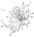
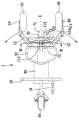
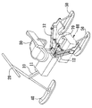
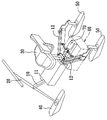
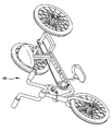
図1ないし図5は、本発明の一実施例による3輪車を説明するための図である。図1は3輪車例の斜視図、図2はその上面図、図3は図2のIII―III線の断面図である。図中、1は3輪車であり、11は該3輪車1の車体10の前後方向Xに延びる車体フレームである。なお、本発明の乗り物は、例えば電動車について説明するが、人力で漕ぐタイプにも利用できる。
1 to 5 are views for explaining a three-wheeled vehicle according to an embodiment of the present invention. 1 is a perspective view of an example of a three-wheeled vehicle, FIG. 2 is a top view thereof, and FIG. 3 is a sectional view taken along line III-III in FIG. In the figure, 1 is a three-wheeled vehicle, and 11 is a body frame extending in the front-rear direction X of the
この車体フレーム11の前部111に、ヘッドパイプや、ヘッドパイプ内に回動自在に挿通しているステアリング軸、ステアリング軸の上端に取り付けられたハンドルからなっている操縦手段20が設けられている。該操縦手段20の下端には、符号で明示しない左右一対のフロントフォークにより前部走行手段としての前輪40が回転自在に軸支されている。車体フレーム11のほぼ中央上方には座姿勢で乗車できる座席30が支持棒13で立設支持されている。車体フレーム11の後部112には、後部走行手段としての後輪50、50をそれぞれ軸支する揺動支持手段としての2アーム12、12が設けられている。2アーム12、12のそれぞれは、アーム本体の一端122が車体フレーム11に座席30の下方に枢着され、他端123が後述の腕アーム511と枢着され、2端122、123の間に後述の離合作動手段70が枢着されている。
The
車体フレーム11の両側に後輪50、50がそれぞれ車軸をヒンジ座513、513を介して対応側のアーム12、12と枢着した腕アーム511、511の軸受け部512、512により回転可能に軸支されている。後輪50、50の車軸と腕アーム511、511の間に走行駆動装置60が設けられている。この例では、揺動支持手段としてのアーム12、12はそれぞれ、平行に配置されたリンク節121、121をそなえた平行四辺形機構からなり、揺動自在で且つ支持強度を補強することができる。走行駆動装置60としてハブモータを用いることができる。また、この例においては、走行駆動装置60としては後輪50に取り付けられているが、これに限らず、前輪などに設けられてもよい。
The
車体フレーム11後部112に、後輪50、50側に連結するように前記2後輪50、50間距離を互いに引き寄せて縮めたり、突張って放したり離合するための離合作動手段70が設けられている。離合作動手段70は、図1から図3のように、車体フレーム11に前後方向に滑り移動可能に設けられているスライダー73と、それぞれの1端721、721がスライダー73と、他端722、722が対応側のアーム12、12と枢着されているロッド72、72と、ピストン部711がスライダー73と連結してスライダー73を車体フレーム11に前後進退移動させることができる往復駆動装置71とからなっている。なお、この例においては、往復駆動装置71としては、ピストン部によりスライダー73を進退作動できるピストンシリンダー装置を用いるが、これに制限されず、周期的にスライダーを進退移動できる送り装置であればよい。
The
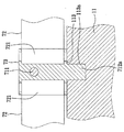
車体フレーム11に、図3に示されているように、前後方向Xに延びる長溝113aを凹設したスライドレール113が設けられ、スライダー73が安定に滑り移動できる。この例においては、スライダー73の底部に凹溝113aに滑り嵌合する突起部73aが形成されている。
As shown in FIG. 3, the
この電動車1に、例えば車体フレーム11において座席30の下方に走行駆動手段60及び離合作動手段70に連結され、それぞれの駆動力を起こすパワー手段80が設けられている。この例においては、パワー手段80は、走行駆動手段(ハブモータ)60と離合作動手段70に電力を供給するための蓄電バッテリーである。
なお、上記において、ペタルなどの図示は省略する。
The electric vehicle 1 is provided with, for example, a
In the above, illustration of petals and the like is omitted.
次に、本実施例にかかる3輪車1の動作を説明する。 Next, the operation of the three-wheeled vehicle 1 according to this embodiment will be described.
まず、図1〜図2に示されているように、パワー手段80が供給するパワーにより、離合作動手段70の往復駆動装置71を駆動させ、ピストン部711を後退させ、ピストン部711と連結されたスライダー73が連動され、滑り移動して後退する。スライダー73と連結されたロッド72、72が連動してほぼ一字状に展開され、アーム12、12が連動され、アーム12、12に軸支された2後輪50、50が展開するように揺動されて、互いに離れて開かられる。このように、3輪車ごとく安定よく減速、駐車することができる。
First, as shown in FIGS. 1 and 2, the power supplied by the power means 80 drives the reciprocating
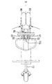
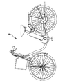
また、図4〜図5に示されているように、離合作動手段70の往復駆動装置71を駆動させ、ピストン部711を前進させ、ピストン部711と連結されたスライダー73が連動し、滑り移動して前進する。スライダー73と連結されたロッド72、72が連動して車体フレーム11側にほぼV字形に引き寄せ、アーム12、12が車体フレーム11にほぼ平行に並列し、後輪50、50を車体フレーム11側に引き寄せて後輪50、50間の距離を縮める。このとき、2輪車のように軽快走行性を付与することができ、また駐車スペースも少なく取らず済むことができる。
このように、2輪車のような走行軽快性及び3輪車のような走行安定性を兼備した乗り物が得られる。
Further, as shown in FIGS. 4 to 5, the
In this way, a vehicle having both driving comfort like a two-wheeled vehicle and driving stability like a three-wheeled vehicle can be obtained.
なお、本発明の乗り物としては上記実施例に限定されることなく、種々変形が可能である。例えば、図6、7に示す実施例に利用できる。なお、これらの実施例では前記実施例の構成とほぼ同様である。これらの図において上記図面に示した機能や構成がほぼ同一要素には同一符号を付しており、以下、それらについての説明は省略する。 The vehicle of the present invention is not limited to the above-described embodiment, and various modifications can be made. For example, it can be used in the embodiments shown in FIGS. In these embodiments, the configuration is substantially the same as that of the above-described embodiment. In these drawings, elements having substantially the same functions and configurations shown in the above drawings are denoted by the same reference numerals, and description thereof will be omitted below.
図6は、本発明の実施例によるスノー乗用車を概略示す斜視図である。前部走行手段40及び後部走行手段50としては、スキー板であり、走行駆動手段60としては、例えばパワー手段80連結され車体フレーム11に設けられているキャタビラー推進装置を用いることができる。
FIG. 6 is a perspective view schematically showing a snow passenger vehicle according to an embodiment of the present invention. The front traveling means 40 and the rear traveling means 50 are skis, and as the traveling drive means 60, for example, a caterpillar propulsion device connected to the power means 80 and provided in the
図7は、本発明にかかる水上乗用車を概略示す斜視図である。前部走行手段40及び後部走行手段50としては、水上浮き板であり、走行駆動手段60としては、プロペラ推進装置を用いることができる。 FIG. 7 is a perspective view schematically showing a water vehicle according to the present invention. The front traveling means 40 and the rear traveling means 50 are floating boards, and the traveling drive means 60 can be a propeller propulsion device.
従って、これらの実施例においても前記実施例と同様の効果が得られる。 Therefore, in these embodiments, the same effects as in the above embodiments can be obtained.
以上の説明で明らかなように、本発明によれば、車体フレームと2後部走行手段との間に設けられた離合作動手段により、2後部走行手段を互いに車体フレーム側に引き寄せて、2後部走行手段間の距離を縮め、2輪車のような走行軽快性を付与することができ、駐車スペースも取らない。また、2後部走行手段を車体フレームから突張って放して、2後部走行手段間の距離を大きくし、3輪車のように安定性よく低速で走ったり、任意に駐車することができる。 As is apparent from the above description, according to the present invention, the two rear running means are pulled toward each other by the disengagement actuating means provided between the vehicle body frame and the two rear running means, so that the two rear running is achieved. The distance between the means can be shortened, and the driving lightness like a two-wheeled vehicle can be provided, and the parking space is not taken. Further, the two rear running means are extended and released from the vehicle body frame, the distance between the two rear running means is increased, and the vehicle can run at a low speed with stability as in a three-wheeled vehicle or can be arbitrarily parked.
1 乗り物
10 車体
11 車体フレーム
12 揺動支持手段(アーム)
20 操縦手段
30 座席
40 前部走行手段
50 後部走行手段
60 走行駆動装置
70 離合作動手段
71 往復駆動装置
72 ロッド
73 スライダー
73a 突起部
80 パワー手段
111 前部
112 後部
113 スライドレール
113a 長溝
121 リンク節
122、123 端
511 腕アーム
512 軸受け部
513 ヒンジ座
711 ピストン部
721、722 端
DESCRIPTION OF SYMBOLS 1
20 Steering means 30
Claims (13)
前記車体フレームに、前記2後部走行手段側と連結し、前記2後部走行手段間距離を互いに引き寄せて縮めたり、突張って放したり離合させるための離合作動手段が設けられていることを特徴とする乗り物。 A vehicle body frame constituting a vehicle body extending longitudinally in the front-rear direction, a steering means connected to the vehicle body frame for controlling the traveling direction of the vehicle body, and a front portion supported and supported by the front of the vehicle body frame In a vehicle comprising travel means and two rear travel means, each of which is pivotally supported on both rear sides of the body frame,
The vehicle body frame is provided with a separation actuating means connected to the side of the two rear traveling means, and for pulling the distance between the two rear traveling means closer to each other and forcing and releasing them. To ride.
前記車体フレームに前後方向に滑り移動可能に設けられているスライダーと、
それぞれの一端部が前記スライダーに枢着され、それぞれの他端部が対応側の前記後部走行手段側に枢着され、前記スライダーの滑り移動に応じて前記2後部走行手段を離合自在に開閉する2ロッド部材と、
からなっていることを特徴とする請求項1に記載の乗り物。 As the separation operation means,
A slider provided on the body frame so as to be slidable in the front-rear direction;
One end of each is pivotally attached to the slider, and the other end is pivotally attached to the corresponding rear running means, and opens and closes the two rear running means in accordance with the sliding movement of the slider. Two rod members;
The vehicle according to claim 1, comprising:
前記スライダーに前記長溝に滑り嵌合する突起部が形成されていることを特徴とする請求項3に記載の乗り物。 A long groove extending in the front-rear direction is formed in the slide rail,
The vehicle according to claim 3, wherein a protrusion is formed on the slider so as to slide and fit into the long groove.
さらに、走行駆動手段が、前記車体を走行させることができるように前記車体フレーム、前記前部走行手段及び前記後部走行手段のいずれかと連設されていることを特徴とする請求項1に記載の乗り物。 The front running means and the rear running means are any of wheels, skis and floating boards,
Further, the travel driving means is connected to any one of the vehicle body frame, the front traveling means, and the rear traveling means so that the vehicle body can travel. vehicle.
前記走行駆動手段としては、前記車輪のハブに設けられたハブモータである請求項9に記載の乗り物。 The front traveling means and the rear traveling means are wheels,
The vehicle according to claim 9, wherein the travel driving means is a hub motor provided on a hub of the wheel.
前記走行駆動手段は、前記車体フレームと連結されたキャタビラー推進装置である請求項9に記載の乗り物。 The front traveling means and the rear traveling means are skis,
The vehicle according to claim 9, wherein the travel driving means is a caterpillar propulsion device connected to the vehicle body frame.
前記走行駆動手段は、前記車体フレームに設けられているプロペラ推進装置である請求項9に記載の乗り物。 The front running means and the rear running means are floating boards,
The vehicle according to claim 9, wherein the travel drive means is a propeller propulsion device provided in the vehicle body frame.
Applications Claiming Priority (1)
| Application Number | Priority Date | Filing Date | Title |
|---|---|---|---|
| TW095124118A TWI291424B (en) | 2006-07-03 | 2006-07-03 | Vehicle with adjustable distance between moving/carrying units |
Publications (2)
| Publication Number | Publication Date |
|---|---|
| JP2008013169A true JP2008013169A (en) | 2008-01-24 |
| JP4637878B2 JP4637878B2 (en) | 2011-02-23 |
Family
ID=38875800
Family Applications (1)
| Application Number | Title | Priority Date | Filing Date |
|---|---|---|---|
| JP2007168819A Expired - Fee Related JP4637878B2 (en) | 2006-07-03 | 2007-06-27 | vehicle |
Country Status (3)
| Country | Link |
|---|---|
| US (1) | US7878522B2 (en) |
| JP (1) | JP4637878B2 (en) |
| TW (1) | TWI291424B (en) |
Cited By (3)
| Publication number | Priority date | Publication date | Assignee | Title |
|---|---|---|---|---|
| JP2010280367A (en) * | 2009-06-08 | 2010-12-16 | Yoshiharu Urata | Bicycle |
| CN103523134A (en) * | 2013-10-15 | 2014-01-22 | 昆明理工大学 | Position-changeable multipurpose bicycle |
| KR20150130446A (en) * | 2013-03-11 | 2015-11-23 | 엔.쥐.엠. 에스피알엘 | Tricycle |
Families Citing this family (29)
| Publication number | Priority date | Publication date | Assignee | Title |
|---|---|---|---|---|
| US7658252B2 (en) * | 2007-07-03 | 2010-02-09 | Shapiro Richard N | Riding vehicles, including tricycles, with stowable push handles and hide away rear wheel storage compartment |
| US8235912B2 (en) * | 2009-03-18 | 2012-08-07 | Acarix A/S | Segmenting a cardiac acoustic signal |
| WO2011136541A2 (en) * | 2010-04-26 | 2011-11-03 | Ko Young Seung | Sliding board |
| KR101319481B1 (en) * | 2012-04-12 | 2013-10-17 | 김정근 | Bicycle frame and bicycle capable of transforming tricycle using the same |
| US9254884B2 (en) * | 2013-03-12 | 2016-02-09 | Huffy Corporation | Wheel mechanism for converting a child vehicle between multiple configurations and associated method |
| US9067633B2 (en) * | 2013-06-12 | 2015-06-30 | Robert Bell | Bicycle convertible to a stroller |
| US9375097B2 (en) | 2013-06-14 | 2016-06-28 | Kids Ii, Inc. | Convertible walker |
| CN103738437B (en) * | 2014-01-23 | 2016-04-27 | 王畅鸿 | Multifunctional tiny novel electric vehicle |
| US20160096574A1 (en) * | 2014-10-01 | 2016-04-07 | Yong-Biao Liu | Tiltable Motor Tricycle |
| CN104554564B (en) * | 2014-12-10 | 2017-08-08 | 盐城雄鹰精密机械有限公司 | A kind of wheel isolating construction based on U-shaped shift fork |
| CN104554568B (en) * | 2014-12-10 | 2017-08-04 | 盐城雄鹰精密机械有限公司 | A kind of car wheel structure of disengaging type |
| CN104554567B (en) * | 2014-12-10 | 2017-11-24 | 盐城市晟方机械有限公司 | A kind of Electricmotor car wheel separate type adjustment structure |
| CN104554569B (en) * | 2014-12-10 | 2017-07-21 | 郑晓媚 | A kind of Portable electric bicycle wheel adjusting means |
| CN107054527B (en) * | 2014-12-10 | 2019-05-24 | 速珂智能科技(上海)有限公司 | A kind of wheel can clutch Portable electric bicycle |
| CN104828188B (en) | 2015-05-20 | 2017-03-29 | 常州爱尔威智能科技有限公司 | Electrodynamic balance car |
| CN104843122B (en) * | 2015-05-26 | 2017-08-25 | 上海理工大学 | The variable rickshaw of multipurpose |
| CN106515958A (en) * | 2016-10-31 | 2017-03-22 | 叶柯 | Convertible two-mode vehicle |
| CN106428355A (en) * | 2016-11-03 | 2017-02-22 | 金壁 | Novel method for changing electro-tricycle into electric bicycle |
| US20180257727A1 (en) * | 2017-03-13 | 2018-09-13 | Jin Ye | Foldable three-wheeled scooter |
| CN107351955B (en) * | 2017-07-25 | 2023-03-31 | 江苏师范大学 | Electric tool for riding instead of walking |
| CN109625136B (en) * | 2018-12-13 | 2023-12-29 | 好孩子儿童用品有限公司 | children's toy car |
| CN110001738A (en) * | 2019-04-24 | 2019-07-12 | 中山市辣妈日用品有限公司 | Baby stroller with variable scooter |
| US11780531B2 (en) * | 2019-10-26 | 2023-10-10 | Massachusetts Institute Of Technology | Methods and apparatus for reconfigurable autonomous vehicle |
| CN112776930A (en) * | 2019-11-11 | 2021-05-11 | 上海艺烁实业有限公司 | Electric vehicle rear wheel frame structure capable of freely switching single wheel and double wheels |
| DE102020118623A1 (en) * | 2020-07-15 | 2022-01-20 | Bayerische Motoren Werke Aktiengesellschaft | Three-wheeled vehicle with a multi-part frame |
| CN114074738A (en) * | 2020-08-10 | 2022-02-22 | 纳恩博(常州)科技有限公司 | Transmission assembly and electric vehicle |
| USD980134S1 (en) * | 2020-10-30 | 2023-03-07 | Hartmut Huber | Scooter |
| CN112319679A (en) * | 2020-11-30 | 2021-02-05 | 刘金毅 | Variable track road surface traveling moving system |
| DE102023122067B4 (en) * | 2023-08-17 | 2026-07-23 | Qeridoo engineering GmbH | Bicycle trailer usable as a stroller, with push handle and adjustable track width |
Citations (3)
| Publication number | Priority date | Publication date | Assignee | Title |
|---|---|---|---|---|
| JPS4827838A (en) * | 1971-08-06 | 1973-04-12 | ||
| JPH0177501U (en) * | 1987-11-13 | 1989-05-25 | ||
| JPH0316890A (en) * | 1989-06-05 | 1991-01-24 | Fu Chao Wan | Foldable amphibian bicycle set |
Family Cites Families (14)
| Publication number | Priority date | Publication date | Assignee | Title |
|---|---|---|---|---|
| US3827519A (en) * | 1971-10-15 | 1974-08-06 | J Snider | Vehicular exerciser apparatus |
| US4277078A (en) * | 1979-02-22 | 1981-07-07 | Root Myron A | Three-wheel conveyance |
| US4540192A (en) * | 1983-12-27 | 1985-09-10 | Shelton L Harvey | Three-wheeled scooter-type vehicle |
| US5265550A (en) * | 1992-09-28 | 1993-11-30 | Harper Jr William H | Water vessel |
| IT1281790B1 (en) * | 1995-05-03 | 1998-03-03 | Carer Snc Dell Ing Angelo Gaet | FOUR-WHEEL FORKLIFT WITH NARROW TURNING RADIUS AND IMPROVED STABILITY |
| US5769441A (en) * | 1995-09-19 | 1998-06-23 | Namngani; Abdulatif | Vehicle having two axially spaced relatively movable wheels |
| IT1321177B1 (en) * | 2000-04-21 | 2003-12-30 | Carrelli Elevatori Cesab | REDUCED STEERING RADIUS FORKLIFT. |
| US20030214113A1 (en) * | 2002-05-02 | 2003-11-20 | Todd Bank | Vehicle having independently articulating rear frame members |
| JP4374367B2 (en) * | 2005-10-28 | 2009-12-02 | ランドウォーカー株式会社 | bicycle |
| ITPD20050032A1 (en) * | 2005-02-11 | 2006-08-12 | Carraro Spa | STEERING AXLE FOR VEHICLES |
| AU2006244602A1 (en) * | 2005-05-05 | 2006-11-16 | Purdue Research Foundation | Vehicle with variable wheel camber |
| US7845666B2 (en) * | 2006-03-06 | 2010-12-07 | Purdue Research Foundation | Swinging hub for adjusting wheel camber |
| DE102007019026A1 (en) * | 2006-10-30 | 2008-10-23 | Steinhilber, Hektor | Vehicle with three wheels |
| US20080277890A1 (en) * | 2007-05-07 | 2008-11-13 | Boster Ii Roger D | Four-Way Forklift With Outwardly Pivoting Wheel Arms |
-
2006
- 2006-07-03 TW TW095124118A patent/TWI291424B/en not_active IP Right Cessation
- 2006-10-10 US US11/546,090 patent/US7878522B2/en not_active Expired - Fee Related
-
2007
- 2007-06-27 JP JP2007168819A patent/JP4637878B2/en not_active Expired - Fee Related
Patent Citations (3)
| Publication number | Priority date | Publication date | Assignee | Title |
|---|---|---|---|---|
| JPS4827838A (en) * | 1971-08-06 | 1973-04-12 | ||
| JPH0177501U (en) * | 1987-11-13 | 1989-05-25 | ||
| JPH0316890A (en) * | 1989-06-05 | 1991-01-24 | Fu Chao Wan | Foldable amphibian bicycle set |
Cited By (5)
| Publication number | Priority date | Publication date | Assignee | Title |
|---|---|---|---|---|
| JP2010280367A (en) * | 2009-06-08 | 2010-12-16 | Yoshiharu Urata | Bicycle |
| KR20150130446A (en) * | 2013-03-11 | 2015-11-23 | 엔.쥐.엠. 에스피알엘 | Tricycle |
| JP2016509975A (en) * | 2013-03-11 | 2016-04-04 | エヌ・ヘー・エム・ソシエテ・プリヴェ・ア・レスポンサビリテ・リミテN.G.M. Sprl | Tricycle |
| KR102233348B1 (en) | 2013-03-11 | 2021-03-31 | 엔.쥐.엠. 에스피알엘 | Tricycle |
| CN103523134A (en) * | 2013-10-15 | 2014-01-22 | 昆明理工大学 | Position-changeable multipurpose bicycle |
Also Published As
| Publication number | Publication date |
|---|---|
| US7878522B2 (en) | 2011-02-01 |
| US20080001374A1 (en) | 2008-01-03 |
| TW200804129A (en) | 2008-01-16 |
| JP4637878B2 (en) | 2011-02-23 |
| TWI291424B (en) | 2007-12-21 |
Similar Documents
| Publication | Publication Date | Title |
|---|---|---|
| JP4637878B2 (en) | vehicle | |
| KR20140046621A (en) | Personal mobility vehicle | |
| CN103274005B (en) | Foldable electric tricycle | |
| KR101288975B1 (en) | Bicycle with baby carrige | |
| US20120181769A1 (en) | Multi-person tricycle | |
| CN106080892B (en) | Segway Human Transporter | |
| CN107922029A (en) | Configurable bicycle and the method that bicycle is changed between the first and second riding configurations | |
| CN201186711Y (en) | Box shaped telescopic foldable bicycle | |
| US6179314B1 (en) | Front wheel drive ride-on vehicle | |
| JP5267781B2 (en) | Walking stick bicycle | |
| WO2016041524A1 (en) | Flipping seat box type folding electric bicycle | |
| TW580471B (en) | Vehicle body structure in saddle-riding type vehicle | |
| JP6482163B2 (en) | Foldable vehicle | |
| CN105501365B (en) | A kind of folding stand and electric motor bicycle with folding | |
| CN219524132U (en) | Four-wheel scooter with electric folding structure | |
| CN116573089B (en) | Four-wheel scooter | |
| CN201002682Y (en) | Sliding vehicle driven by user side movement | |
| CN201756156U (en) | Box-type folding bike | |
| JP2002249091A (en) | Folding bicycle with X-shaped frame also used as carrier | |
| CN202243866U (en) | Folding electric tricycle | |
| CN216709545U (en) | Telescopic electric bicycle | |
| CN224112239U (en) | Electric suitcase | |
| CN201901223U (en) | Portable folding electric motor car | |
| CN2799383Y (en) | Foot and electric driven dual-purpose bicycle capable of being folded into three segments | |
| CN101607575A (en) | Collapsiblely be folded into box-type car |
Legal Events
| Date | Code | Title | Description |
|---|---|---|---|
| A131 | Notification of reasons for refusal |
Free format text: JAPANESE INTERMEDIATE CODE: A131 Effective date: 20100126 |
|
| A521 | Request for written amendment filed |
Free format text: JAPANESE INTERMEDIATE CODE: A523 Effective date: 20100420 |
|
| TRDD | Decision of grant or rejection written | ||
| A01 | Written decision to grant a patent or to grant a registration (utility model) |
Free format text: JAPANESE INTERMEDIATE CODE: A01 Effective date: 20101026 |
|
| A01 | Written decision to grant a patent or to grant a registration (utility model) |
Free format text: JAPANESE INTERMEDIATE CODE: A01 |
|
| A61 | First payment of annual fees (during grant procedure) |
Free format text: JAPANESE INTERMEDIATE CODE: A61 Effective date: 20101124 |
|
| FPAY | Renewal fee payment (event date is renewal date of database) |
Free format text: PAYMENT UNTIL: 20131203 Year of fee payment: 3 |
|
| R150 | Certificate of patent or registration of utility model |
Free format text: JAPANESE INTERMEDIATE CODE: R150 |
|
| R250 | Receipt of annual fees |
Free format text: JAPANESE INTERMEDIATE CODE: R250 |
|
| R250 | Receipt of annual fees |
Free format text: JAPANESE INTERMEDIATE CODE: R250 |
|
| R250 | Receipt of annual fees |
Free format text: JAPANESE INTERMEDIATE CODE: R250 |
|
| LAPS | Cancellation because of no payment of annual fees |