JP2008021990A - Electromagnetic interference suppressor and electromagnetic interference suppression method - Google Patents
Electromagnetic interference suppressor and electromagnetic interference suppression method Download PDFInfo
- Publication number
- JP2008021990A JP2008021990A JP2007160569A JP2007160569A JP2008021990A JP 2008021990 A JP2008021990 A JP 2008021990A JP 2007160569 A JP2007160569 A JP 2007160569A JP 2007160569 A JP2007160569 A JP 2007160569A JP 2008021990 A JP2008021990 A JP 2008021990A
- Authority
- JP
- Japan
- Prior art keywords
- electromagnetic interference
- sheet
- binder
- interference suppressor
- drying
- Prior art date
- Legal status (The legal status is an assumption and is not a legal conclusion. Google has not performed a legal analysis and makes no representation as to the accuracy of the status listed.)
- Pending
Links
Images



Landscapes
- Soft Magnetic Materials (AREA)
- Shielding Devices Or Components To Electric Or Magnetic Fields (AREA)
- Laminated Bodies (AREA)
- Hard Magnetic Materials (AREA)
Abstract
【課題】磁性塗料を塗布、乾燥して得られるシート状の電磁干渉抑制体において、優れた電磁干渉抑制効果を有する電磁干渉抑制体を提供することである。
【解決手段】磁性塗料を塗布、乾燥して得られるシート状の電磁干渉抑制体であって、軟磁性粉末30〜80体積%と結合剤20〜70体積%とを含有し、20〜60℃における貯蔵弾性率(E’)が109Pa以上(JIS K 7244−1)である。結合剤は、数平均分子量(Mn)がMn≧1.5×10⁴で、且つ20〜60℃における溶剤および充填剤を含有しない状態の貯蔵弾性率(E’)が107Pa(JIS K 7244−1)以上であるエラストマーまたは樹脂である。
【選択図】なしAn object of the present invention is to provide an electromagnetic interference suppressor having an excellent electromagnetic interference suppression effect in a sheet-like electromagnetic interference suppressor obtained by applying and drying a magnetic paint.
A sheet-like electromagnetic interference suppressor obtained by applying and drying a magnetic paint, containing 30 to 80% by volume of soft magnetic powder and 20 to 70% by volume of a binder, and having a temperature of 20 to 60 ° C. The storage elastic modulus (E ′) at 10 is 10 9 Pa or more (JIS K 7244-1). The binder has a number average molecular weight (Mn) of Mn ≧ 1.5 × 10 4 and a storage elastic modulus (E ′) of 10 7 Pa (JIS K) containing no solvent and filler at 20 to 60 ° C. 7244-1) or higher elastomer or resin.
[Selection figure] None
Description
本発明は、電子機器内の不要電磁波の干渉によって生じる電磁障害を抑制するために用いられる電磁干渉抑制体、これを用いる電磁障害抑制方法に関する。 The present invention relates to an electromagnetic interference suppressing body used for suppressing electromagnetic interference caused by interference of unnecessary electromagnetic waves in an electronic device, and an electromagnetic interference suppressing method using the same.
近年、テレビなどの家庭電気製品、パーソナルコンピューターなどのコンピューター、携帯電話などの移動体通信機器、医療機器など各種の電子機器が広く使われており、これら電子機器から放出された不要電磁波は他の電子機器に影響を与えて誤作動を発生させるなどの悪影響を及ぼしている。そのため、このような電子機器において、不要電磁波を取り除く、あるいは遮蔽する電磁干渉抑制体が使用されている。 In recent years, various electronic devices such as home electric appliances such as televisions, computers such as personal computers, mobile communication devices such as mobile phones, and medical devices have been widely used. Unwanted electromagnetic waves emitted from these electronic devices It adversely affects electronic devices and causes malfunctions. Therefore, in such an electronic device, an electromagnetic interference suppressor that removes or shields unnecessary electromagnetic waves is used.
また、上記電子機器類は、近年、高速化、軽量化、薄型化および小型化も急速に進み、回路への電子部品の実装密度が飛躍的に高くなっている。このため、部品間や回路基板間の電磁干渉に起因する電磁ノイズの増大に伴い、電子機器内にて部品間や回路基板間でも不要電磁波による電磁障害が発生する可能性が高くなっている。 In recent years, the electronic devices have been rapidly increased in speed, weight, thickness and size, and the mounting density of electronic components on a circuit has been dramatically increased. For this reason, along with an increase in electromagnetic noise caused by electromagnetic interference between components and circuit boards, there is a high possibility that electromagnetic interference due to unnecessary electromagnetic waves occurs between components and circuit boards in an electronic device.
電磁障害を抑制する対策の一つとして、特許文献1には、結合剤中に軟磁性体粉末を分散させたシート状の電磁干渉抑制体を電子部品や回路の近傍に配置することが開示されている。
こうした電磁干渉抑制体を使用するにおいて、数10MHz〜数GHzの領域で、高い透磁率を持ったシートが要求される。高い透磁率は、軟磁性粉末として球状ではなく扁平な形状を持つものを使用し、かつ、この扁平軟磁性粉末を電磁干渉抑制シートの面に沿って配向させることが知られている(特許文献2)。
As one of the countermeasures for suppressing electromagnetic interference,
In using such an electromagnetic interference suppressor, a sheet having high magnetic permeability is required in the region of several tens of MHz to several GHz. It is known that a high magnetic permeability uses a soft magnetic powder having a flat shape rather than a spherical shape, and this flat soft magnetic powder is oriented along the surface of the electromagnetic interference suppression sheet (Patent Literature). 2).
配向を容易に行なうには、マトリックス材料として流動性の高いものを使用することが好ましい。例えば、特許文献2には、扁平軟磁性粉末と高分子結合剤とを有機溶媒中に溶解した磁性塗料を、ドクターブレード法により剥離性支持体上に塗工および乾燥してシート化する技術が記載されている。しかしながら、この加工方法を用いると、乾燥時に磁性塗料中の溶剤が発泡するため、シート中に大量の空孔ができるという問題が生じる。大量の空孔が生じると、電磁干渉抑制効果が大幅に低下してしまう。従って、空孔の発生をできるだけおさえ、軟磁性粉末を高密度で充填することが望まれる。
In order to facilitate orientation, it is preferable to use a material having high fluidity as the matrix material. For example,
一方、特許文献3には、扁平軟磁性粉末と結合剤を混合、混練して得られる混和物を、所定の方法でシート成型する複合磁性体の製造方法において、前記結合剤はガラス転移点が50℃以上の塩化ビニル系樹脂を含んでなる複合磁性体の製造方法が記載されている。しかしながら、この方法では、得られる複合磁性体を高密度化するために、製膜、溶媒除去後のシートにプレスやロールを用いた圧延装置で加圧する工程を必要とする。
On the other hand, in
プレス工程やカレンダー工程などの後工程(加圧工程)は、プレスなどで剪断力をシートに付加することにより、シート内の空隙を排出し、さらに充填剤間の狭い間隙にも十分な結合剤の流動を促進することで、密な充填を実現し、シートの比重を大きく向上させることに寄与していた。この後工程は、シートの材料定数(ε’、ε”、μ’、μ”)の最適化設計をするうえで重要な工程である。しかし、プレス工程などを導入すると製造コストが大きく上昇してしまう欠点があった。
従って、従来から、塗工工程のみで高性能なシート状電波干渉抑制体を得ることが要望されていた。
Post-process (pressing process) such as pressing process and calendering process applies shearing force to the sheet by pressing, etc. to discharge the voids in the sheet, and it is also a sufficient binder for narrow gaps between fillers By promoting the flow of the sheet, close packing was realized and the specific gravity of the sheet was greatly improved. This post process is an important process in optimizing the material constants (ε ′, ε ″, μ ′, μ ″) of the sheet. However, when a press process or the like is introduced, there is a drawback that the manufacturing cost increases greatly.
Therefore, conventionally, there has been a demand for obtaining a high-performance sheet-like radio wave interference suppressing body only by a coating process.
シート状電波干渉抑制体は、結合剤を溶媒に溶かした溶液をつくり、そこに軟磁性粉体を混入、撹拌し、塗工装置にて支持材に塗布し、乾燥して製造することができる。以上の工程で、シート内にエアー(溶剤痕)が残らない状態を得るためには、(a)塗液に入るエアーを少なくする方法と、(b)塗工後のエアー残存量を少なくする方法とに分けて考えることができる。(a)については、(1)塗液設計時の溶剤量を最小化する、(2)撹拌時および塗工時に泡立てない(初期混入を最小限に抑える)、(3)塗工直前に真空脱泡する、があり、(b)については、溶剤の揮発速度をシート乾燥固化速度より同じか早くする、がある。
現実の製造工程では、製造速度を上げるため、塗工後、風乾を経て、すぐに高温にした加熱ゾーンを通過させる方法がとられている。その結果、シート乾燥速度>溶剤揮発速度となり、とくに最初に熱の伝わる表層部のみに皮膜を作成するため、内部のエアー(溶剤)が抜けきらず、内部に空孔が生じることになり、シート自体の比重が上がりきらないという問題があった。
The sheet-like radio wave interference suppressor can be manufactured by preparing a solution in which a binder is dissolved in a solvent, mixing and stirring the soft magnetic powder therein, applying it to a support material with a coating apparatus, and drying it. . In order to obtain a state in which no air (solvent trace) remains in the sheet in the above steps, (a) a method of reducing the amount of air entering the coating liquid, and (b) reducing the residual amount of air after coating. It can be divided into methods. For (a), (1) Minimize the amount of solvent when designing the coating solution, (2) No foaming during stirring and coating (minimize initial contamination), (3) Vacuum immediately before coating For (b), the volatilization rate of the solvent is the same as or faster than the sheet drying and solidification rate.
In an actual manufacturing process, in order to increase the manufacturing speed, a method of passing through a heating zone immediately heated to high temperature after coating is air-dried. As a result, the sheet drying rate> solvent volatilization rate, and in particular, since a film is created only on the surface layer where heat is transferred first, the internal air (solvent) is not completely removed, and voids are generated inside the sheet itself. There was a problem that the specific gravity did not increase.
本発明の課題は、磁性塗料を塗布、乾燥して得られるシート状の電磁干渉抑制体において、優れた電磁干渉抑制効果を有する電磁干渉抑制体を提供することである。より詳細には、本発明は、塗工および乾燥工程のみで得られ、プレス工程やカレンダー工程などの後工程が不要で、しかも後工程を施した場合と同様の高性能(高い比重およびそれにより達成される最適な複素比透磁率の実数部μ’および/または虚数部μ”)を有する電磁干渉抑制体を提供することである。 The subject of this invention is providing the electromagnetic interference suppression body which has the outstanding electromagnetic interference suppression effect in the sheet-like electromagnetic interference suppression body obtained by apply | coating and drying a magnetic coating material. More specifically, the present invention is obtained only by the coating and drying process, does not require a post-process such as a press process or a calendar process, and has the same high performance (high specific gravity and thereby) as when the post-process is performed. It is to provide an electromagnetic interference suppressor having a real part μ ′ and / or an imaginary part μ ″) of the optimum complex relative permeability to be achieved.
本発明者らは、特に前記した(b)に着目し、いかにエアー(溶剤)の抜け出しを速くするかを検討した。その結果、本発明者らは、磁性塗料を塗布、乾燥するだけで空孔の影響による電磁干渉抑制効果の低下が抑制されると共に高密度化でき、不要電磁波の干渉によって生じる電磁障害を抑制するのに有用な電磁干渉抑制体を得ることに成功した。 The inventors of the present invention particularly focused on (b) described above and studied how to make air (solvent) escape faster. As a result, the present inventors can suppress the decrease in the electromagnetic interference suppression effect due to the influence of the pores and simply increase the density by simply applying and drying the magnetic paint, and suppress the electromagnetic interference caused by the interference of unnecessary electromagnetic waves. We succeeded in obtaining a useful electromagnetic interference suppressor.
すなわち、課題を解決するための本発明の電磁干渉抑制体は、下記(1)〜(9)の構成からなる。
(1)磁性塗料を塗布、乾燥して得られるシート状の電磁干渉抑制体であって、軟磁性粉末30〜80体積%と結合剤20〜70体積%とを含有し、20〜60℃における貯蔵弾性率(E’)が109Pa以上(JIS K 7244−1)であることを特徴とする電磁干渉抑制体。
(2)磁性塗料を塗布、乾燥して得られるシート状の電磁干渉抑制体であって、軟磁性粉末30〜80体積%と結合剤20〜70体積%とを含有し、前記結合剤は、Mn≧1.5×10⁴、且つ20〜60℃における貯蔵弾性率(E’)が107Pa(JIS K 7244−1)以上であるエラストマーまたは樹脂であることを特徴とする電磁干渉抑制体。
(3)前記シート状の電磁干渉抑制体は、実質的に加圧することなく製造されていることを特徴とする(1)または(2)に記載の電磁干渉抑制体。
ここで、「実質的に加圧することなく」とは、プレス加工やカレンダー加工等のような高圧での加圧を受けないで製造されたことを意味し、例えば製造時、貯蔵時、保管時等における製品またはその中間体がロール巻き、積載などにより受ける不可避的な加圧は含まれない。同様に、低圧での簡易なカレンダーも含まれない。
(4)結合剤に架橋を施したことを特徴とする(1)〜(3)のいずれかに記載の電磁干渉抑制体。
(5)100MHzおよび1GHzの周波数で、複素比透磁率の実数部(μ’)が5以上、または虚数部(μ”)が5以上であることを特徴とする(1)〜(4)のいずれかに記載の電磁干渉抑制体。
(6)100MHzおよび1GHzの周波数で、複素比誘電率の虚数部(ε”)が500以下であることを特徴とする(1)〜(5)のいずれかに記載の電磁干渉抑制体。
(7)難燃性を付与したことを特徴とする(1)〜(6)のいずれかに記載の電磁干渉抑制体。
(8)少なくとも一方の表面に、粘着剤層または接着剤層を有することを特徴とする(1)〜(7)のいずれかに記載の電磁干渉抑制体。
(9)導電性反射層と、この導電性反射層の少なくとも片面に設けられた(1)〜(8)のいずれかに記載の電磁干渉抑制体とを備え、10MHz〜1GHzに於けるKEC法またはアドバンテスト法で得られる磁界シールド性が10dB以上であることを特徴とする磁気シールドシート。
本発明の電磁障害抑制方法は、上記電磁干渉抑制体を電子機器類の内部または周辺部に配置することを特徴とする。
That is, the electromagnetic interference suppressing body of the present invention for solving the problems has the following configurations (1) to (9).
(1) A sheet-like electromagnetic interference suppressor obtained by applying and drying a magnetic paint, containing 30 to 80% by volume of soft magnetic powder and 20 to 70% by volume of a binder at 20 to 60 ° C. An electromagnetic interference suppressor having a storage elastic modulus (E ′) of 10 9 Pa or more (JIS K 7244-1).
(2) A sheet-like electromagnetic interference suppressor obtained by applying and drying a magnetic paint, comprising 30 to 80% by volume of soft magnetic powder and 20 to 70% by volume of a binder, An electromagnetic interference suppressor characterized by being an elastomer or a resin having Mn ≧ 1.5 × 10 4 and a storage elastic modulus (E ′) at 20 to 60 ° C. of 10 7 Pa (JIS K 7244-1) or more. .
(3) The electromagnetic interference suppressor according to (1) or (2), wherein the sheet-like electromagnetic interference suppressor is manufactured without being substantially pressurized.
Here, “without substantially pressurizing” means that it was manufactured without being pressurized under high pressure such as pressing or calendering. For example, at the time of manufacture, storage, storage The unavoidable pressurization that the product or its intermediate body receives by rolling or loading is not included. Similarly, a simple calendar at low pressure is not included.
(4) The electromagnetic interference suppressor according to any one of (1) to (3), wherein the binder is crosslinked.
(5) The real part (μ ′) of the complex relative permeability is 5 or more or the imaginary part (μ ″) is 5 or more at the frequencies of 100 MHz and 1 GHz. The electromagnetic interference suppression body in any one.
(6) The electromagnetic interference suppressor according to any one of (1) to (5), wherein the imaginary part (ε ″) of the complex relative dielectric constant is 500 or less at frequencies of 100 MHz and 1 GHz.
(7) The electromagnetic interference suppressor according to any one of (1) to (6), wherein flame retardancy is imparted.
(8) The electromagnetic interference suppressor according to any one of (1) to (7), which has an adhesive layer or an adhesive layer on at least one surface.
(9) A KEC method at 10 MHz to 1 GHz, comprising a conductive reflective layer and the electromagnetic interference suppressor according to any one of (1) to (8) provided on at least one surface of the conductive reflective layer. Or the magnetic shielding sheet | seat characterized by the magnetic field shielding property obtained by the Advantest method being 10 dB or more.
The electromagnetic interference suppression method of the present invention is characterized in that the electromagnetic interference suppression body is disposed in or around an electronic device.
本発明の電磁干渉抑制体は、前記(1)〜(4)によれば、所定の貯蔵弾性率を有するエラストマーまたは樹脂を結合剤として用いるので、塗布、乾燥するだけで空孔の影響による電磁干渉抑制効果の低下が抑制されると共に高密度化でき、優れた電磁干渉抑制効果が得られるという効果がある。
前記(5)によれば、100MHzおよび1GHzの周波数で、所定の複素比透磁率を有するので前記周波数域の電磁波を吸収および減衰することができ、該電磁波に対して不要放射ノイズ等を抑制することができる。
前記(6)によれば、100MHzおよび1GHzの周波数で、所定の複素比誘電率の虚数部の値を有するので、その周波数において低導電率または高抵抗率となることから、電磁干渉抑制体自身が電磁波を反射しないという効果がある。
前記(7)によれば、電磁干渉抑制体に難燃性が付与されていると、難燃性が要求される用途にも好適に適用することができる。例えば、携帯電話を含む電子情報伝達装置やパソコンその他の電子機器は、難燃性を要求される場合がある。
前記(8)によれば、電磁干渉抑制体の表面に粘着剤層または接着剤層を設けると、電磁干渉抑制体を他の物品に貼着させることができ、これによって電磁干渉抑制体の取り付けが容易になる。
前記(9)によれば、導電性反射層を本発明の電磁干渉抑制体と積層して得られるシートは、絶縁性、磁気シールド性、およびノイズ抑制効果が得られるという効果がある。
従って、本発明の電磁障害抑制方法によれば、本発明の電磁干渉抑制体を電子機器類の内部または周辺部に配置するので、不要電磁波の干渉によって生じる電磁障害を抑制することができる。
According to the electromagnetic interference suppressing body of the present invention, according to the above (1) to (4), an elastomer or a resin having a predetermined storage elastic modulus is used as a binder. There is an effect that a decrease in the interference suppression effect is suppressed and the density can be increased, and an excellent electromagnetic interference suppression effect can be obtained.
According to the above (5), since it has a predetermined complex relative permeability at frequencies of 100 MHz and 1 GHz, it can absorb and attenuate electromagnetic waves in the frequency range, and suppress unnecessary radiation noise and the like with respect to the electromagnetic waves. be able to.
According to said (6), since it has the value of the imaginary part of the predetermined complex relative permittivity at the frequencies of 100 MHz and 1 GHz, the electromagnetic interference suppressor itself has low conductivity or high resistivity at that frequency. Has the effect of not reflecting electromagnetic waves.
According to said (7), if the electromagnetic interference suppression body is provided with flame retardance, it can be applied suitably also to the use for which flame retardance is requested | required. For example, electronic information transmission devices including mobile phones, personal computers, and other electronic devices may be required to have flame retardancy.
According to the above (8), when the pressure-sensitive adhesive layer or the adhesive layer is provided on the surface of the electromagnetic interference suppressor, the electromagnetic interference suppressor can be attached to another article, thereby attaching the electromagnetic interference suppressor. Becomes easier.
According to said (9), the sheet | seat obtained by laminating | stacking an electroconductive reflection layer with the electromagnetic interference suppression body of this invention has an effect that an insulation, magnetic shielding property, and a noise suppression effect are acquired.
Therefore, according to the electromagnetic interference suppressing method of the present invention, the electromagnetic interference suppressing body of the present invention is disposed in or around the electronic equipment, so that electromagnetic interference caused by interference of unnecessary electromagnetic waves can be suppressed.
本発明の電磁干渉抑制体は、軟磁性粉末と結合剤とを主要構成材料とし、主として(薄型磁性)シート状の形態で使用される。本発明の電磁干渉抑制体は、主に結合剤と充填剤にて構成される。ここでいう充填剤は、軟磁性粉末、架橋剤、分散剤、難燃剤、難燃助剤、可塑剤等の結合剤以外の一切の成分の総称である。また磁性塗料は、電磁干渉抑制体の成分を溶剤にて塗液にしたもので、加工工程を終えると溶剤はシートから乾燥排出されることになる。 The electromagnetic interference suppressor of the present invention is mainly used in the form of a (thin magnetic) sheet, with soft magnetic powder and a binder as main constituent materials. The electromagnetic interference suppressor of the present invention is mainly composed of a binder and a filler. A filler here is a general term for all components other than binders, such as a soft magnetic powder, a crosslinking agent, a dispersing agent, a flame retardant, a flame retardant adjuvant, and a plasticizer. In addition, the magnetic paint is obtained by applying a component of the electromagnetic interference suppressor with a solvent, and when the processing step is completed, the solvent is dried and discharged from the sheet.
前記軟磁性粉末としては、例えば磁性ステンレス(Fe−Cr−Al−Si合金)、センダスト(Fe−Si−Al合金)、パーマロイ(Fe−Ni合金)、ケイ素銅(FeッCuッSi合金)、Fe−Si合金、Fe−Si−B(−Cu−Nb)合金、Fe−Ni−CrッSi合金、FeッSi−Cr合金、FeッSi−Al−Ni−Cr合金等のFe系合金の全てが挙げられる。また、フェライト若しくは純鉄粒子を用いても良い。アモルファス合金(Co系、Fe系、Ni系など)、非アモルファス合金(Co系、Fe系、Ni系など)、電磁軟鉄、Fe−Al系合金を用いることもできる。それらが酸化物であっても、一部に酸化構造を有するものでも良い。フェライトとしては、例えばMn−Znフェライト、Ni−Znフェライト、Mn−Mgフェライト、Mnフェライト、Cu−Znフェライト、Cu−Mg−Znフェライトなどのソフトフェライト、あるいは永久磁石材料であるハードフェライトが挙げられる。鉄系酸化物としては、マグネタイトなどがある。Co系酸化物(Co−Zr−O系、Co−Pb−Al−O系など)としては、グラニュラー膜を用いることができる。Fe純鉄粒子としては例えばカルボニル鉄粉が挙げられる。軟磁性粉末の形状(球状、扁平状、繊維状等)に限定されるものではないが、好ましくは透磁率の高い扁平状の軟磁性粉末を使用するのがよい。ただし、扁平状の方がシート内部のエアー(溶剤)が抜けにくく、乾燥後の比重が上がらない傾向がある。これら磁性材料は、単体で使用するほか、複数をブレンドしても構わない。軟磁性粉末の平均粒径または扁平状軟磁性粉末の長径は1〜300・m、好ましくは20〜100・mであるのがよい。また、扁平状軟磁性粉末のアスペクト比は2〜500、好ましくは10〜100であるのがよい。なお、前記平均粒径は、粒度分布測定装置で測定して得られる値である。 Examples of the soft magnetic powder include magnetic stainless steel (Fe-Cr-Al-Si alloy), sendust (Fe-Si-Al alloy), permalloy (Fe-Ni alloy), silicon copper (Fe-Cu-Si alloy), Fe-based alloys such as Fe-Si alloy, Fe-Si-B (-Cu-Nb) alloy, Fe-Ni-Cr-Si alloy, Fe-Si-Cr alloy, Fe-Si-Al-Ni-Cr alloy, etc. All are listed. Further, ferrite or pure iron particles may be used. Amorphous alloys (Co-based, Fe-based, Ni-based, etc.), non-amorphous alloys (Co-based, Fe-based, Ni-based, etc.), electromagnetic soft iron, and Fe-Al based alloys can also be used. They may be oxides or may have an oxide structure in part. Examples of the ferrite include soft ferrite such as Mn—Zn ferrite, Ni—Zn ferrite, Mn—Mg ferrite, Mn ferrite, Cu—Zn ferrite, and Cu—Mg—Zn ferrite, or hard ferrite that is a permanent magnet material. . Examples of iron-based oxides include magnetite. As the Co-based oxide (Co-Zr-O-based, Co-Pb-Al-O-based, or the like), a granular film can be used. Examples of Fe pure iron particles include carbonyl iron powder. The shape of the soft magnetic powder (spherical, flat, fibrous, etc.) is not limited, but it is preferable to use a flat soft magnetic powder with high magnetic permeability. However, in the flat shape, air (solvent) inside the sheet is less likely to escape, and the specific gravity after drying tends not to increase. These magnetic materials may be used alone or in combination. The average particle diameter of the soft magnetic powder or the long diameter of the flat soft magnetic powder is 1 to 300 · m, preferably 20 to 100 · m. The aspect ratio of the flat soft magnetic powder is 2 to 500, preferably 10 to 100. The average particle size is a value obtained by measuring with a particle size distribution measuring device.
軟磁性粉末は、必要に応じてその表面が表面処理されているのが好ましい。表面処理としてはカップリング剤処理や界面活性剤などによる一般的な処理のほか、樹脂コーティングを行ってもよい。これにより、後述する結合剤との親和性が向上するため、軟磁性粉末を高密度に充填することができる。前記カップリング剤としては、例えばシランカップリング剤、チタン系カップリング剤、アルミネート系カップリング剤、アミノ系カップリング剤、カチオン系カップリング剤、ノニオン系カップリング剤等が挙げられ、その使用量は、軟磁性粉末に対して約0.01〜5重量%であるのがよい。また、前記樹脂コーティングする樹脂としては、使用する結合剤と同じか、あるいは使用する結合剤との親和性に優れたエラストマー、樹脂(例えば熱可塑性エラストマー、各種プラスチック)等が挙げられる。このエラストマーおよび樹脂としては、後述する結合剤で例示するものと同じものが挙げられる。この樹脂のコーティング量は、軟磁性粉末に対して約0.01〜10重量%であるのがよい。さらに、軟磁性粉末の表面は、上記カップリング剤処理や樹脂コーティングに加えて、その他の添加剤等により表面処理されていてもよい。この場合の処理量は、軟磁性粉末に対して約0.01〜10重量%であるのがよい。他の表面処理材としては、シリカ、Si系化合物、有機金属複合体、金属酸化物などがある。これらで軟磁性粉末を被覆することで、分散性の向上とともに、電磁干渉抑制体の電気抵抗値を増すことが可能である。ZnO、Zn系酸化物、酸化皮膜を付与することで電磁干渉抑制体の電気抵抗値の増加と耐食性の向上を得ることができる。 The surface of the soft magnetic powder is preferably surface-treated as necessary. As the surface treatment, in addition to a general treatment such as a coupling agent treatment or a surfactant, resin coating may be performed. Thereby, since affinity with the binder mentioned later improves, soft magnetic powder can be filled with high density. Examples of the coupling agent include a silane coupling agent, a titanium coupling agent, an aluminate coupling agent, an amino coupling agent, a cationic coupling agent, and a nonionic coupling agent. The amount should be about 0.01 to 5% by weight based on the soft magnetic powder. Examples of the resin to be coated with the resin include elastomers and resins (for example, thermoplastic elastomers and various plastics) that are the same as the binder used or have excellent affinity with the binder used. As this elastomer and resin, the same thing as what is illustrated with the binder mentioned later is mentioned. The coating amount of the resin is preferably about 0.01 to 10% by weight with respect to the soft magnetic powder. Further, the surface of the soft magnetic powder may be surface-treated with other additives in addition to the above-described coupling agent treatment and resin coating. The treatment amount in this case is preferably about 0.01 to 10% by weight with respect to the soft magnetic powder. Examples of other surface treatment materials include silica, Si-based compounds, organometallic composites, and metal oxides. By coating the soft magnetic powder with these, it is possible to improve the dispersibility and increase the electric resistance value of the electromagnetic interference suppressor. By adding ZnO, a Zn-based oxide, and an oxide film, an increase in the electrical resistance value and an improvement in corrosion resistance of the electromagnetic interference suppressor can be obtained.
本発明の結合剤としては、エラストマーまたは樹脂が使用可能であり、前記エラストマーとしては、例えば塩素化ポリエチレン、塩化ビニルのような塩素系、SBS系ポリマーのようなポリスチレン系、EPDMのようなポリオレフィン系、ポリウレタン系、ポリエステル系、ポリアミド系、フッ素系、シリコーン系等の各種エラストマー(熱可塑性エラストマーを含む)が挙げられる。ゴム系の材料も種類を問わないが、貯蔵弾性率の数値範囲を満たすものが使用できる。
前記樹脂としては、例えばポリエステル系ウレタン樹脂(アジペート系、カーボネート系、カプロラクタムエステル系等)、ポリエーテル系ウレタン樹脂、ポリビニルアセタール樹脂、ポリエチレン、ポリプロピレン、AS樹脂、ABS樹脂、ポリスチレン、ポリ塩化ビニル、ポリ塩化ビニリデン、ポリ酢酸ビニル、エチレン−酢酸ビニル共重合体、フッ素樹脂、アクリル系樹脂、メタクリル酸エステル樹脂、アクリル酸モノマーと他のモノマーを共重合した合成樹脂、ナイロン、ポリカーボネート、ポリエチレンテレフタレート、ポリエチレンナフタレート、ポリブチレンテレフタレート、ポリブタジエン樹脂、アルキド樹脂、不飽和ポリエステル、ポリスルホン、ポリウレタン樹脂(ポリエステル系、ポリエーテル系以外の上述以外の全てのタイプ)、ウレア樹脂、イミド系樹脂、フェノール樹脂、尿素樹脂、エポキシ樹脂、シリコーン樹脂、メラミン樹脂、アクリル樹脂、アクリル系共重合体系、アルキルアクリル系、アイオノマー樹脂、生分解性樹脂、リサイクル樹脂等の熱可塑性樹脂または熱硬化性樹脂が挙げられる。これらのエラストマーまたは樹脂は、単独で用いても良いし、変性処理(グラフト、共重合、化学処理等)を施したものを用いても良いし、複合系(ブレンド、ポリマーアロイ、コンポジット等)で用いることもできる。アクリルシリコーン、アクリルウレタン、アクリルラッカー、各種プライマー、フッ素系塗料、シリコーン系塗料、UV塗料、塗料に配合することもできる。これらのエラストマー及び樹脂等は、凝集力を向上させるため官能基(グリシジル基、カルボキシル基、スルフォン酸基、マレイン酸基、アミノ基等の極性基等、例えば金属塩や4級アミン等を介してアイオノマーを形成できる極性基)を付与することもできる。
As the binder of the present invention, an elastomer or a resin can be used. Examples of the elastomer include a chlorinated polyethylene, a chlorine type such as vinyl chloride, a polystyrene type such as an SBS type polymer, and a polyolefin type such as EPDM. , Various elastomers (including thermoplastic elastomers) such as polyurethane, polyester, polyamide, fluorine, and silicone. The type of rubber material is not limited, but a material satisfying the numerical range of storage elastic modulus can be used.
Examples of the resin include polyester urethane resin (adipate, carbonate, caprolactam ester, etc.), polyether urethane resin, polyvinyl acetal resin, polyethylene, polypropylene, AS resin, ABS resin, polystyrene, polyvinyl chloride, poly Vinylidene chloride, polyvinyl acetate, ethylene-vinyl acetate copolymer, fluorine resin, acrylic resin, methacrylic ester resin, synthetic resin copolymerized with acrylic acid monomer and other monomers, nylon, polycarbonate, polyethylene terephthalate, polyethylene Phthalate, polybutylene terephthalate, polybutadiene resin, alkyd resin, unsaturated polyester, polysulfone, polyurethane resin (all other than those described above except polyester and polyether) Type), urea resin, imide resin, phenol resin, urea resin, epoxy resin, silicone resin, melamine resin, acrylic resin, acrylic copolymer system, alkyl acrylic resin, ionomer resin, biodegradable resin, recycled resin, etc. These thermoplastic resins or thermosetting resins can be mentioned. These elastomers or resins may be used alone, or may be used after modification (grafting, copolymerization, chemical treatment, etc.), or in a composite system (blend, polymer alloy, composite, etc.) It can also be used. It can also be blended in acrylic silicone, acrylic urethane, acrylic lacquer, various primers, fluorine paint, silicone paint, UV paint, paint. These elastomers and resins have a functional group (such as a polar group such as a glycidyl group, a carboxyl group, a sulfonic acid group, a maleic acid group, an amino group, etc., for example, a metal salt or a quaternary amine to improve cohesion. A polar group capable of forming an ionomer).
本発明における結合剤は、室温(例えば25℃での室温乾燥の場合)における後述する溶剤及び充填剤を含有しない状態の貯蔵弾性率(E’)が107Pa(JIS K 7244−1)以上である。室温乾燥(例えば25℃)による場合、その温度での貯蔵弾性率(E’)が107Pa以上がよい。好ましくは、室温での貯蔵弾性率(E’)が108Pa以上がよい。結合剤及び充填剤の系(電磁干渉抑制体製品)では、室温での貯蔵弾性率(E’)が109Pa以上がよい。結合剤及び充填剤を含有したシートでは、室温での貯蔵弾性率(E’)が109Pa以上であるのがより好ましい。強制乾燥(例えば50℃以上)に対応するためには、例えば55℃においても溶剤及び充填剤を含有しない状態での貯蔵弾性率(E’)が107Pa以上がよい。好ましくは、108Pa以上がよい。つまり、室温乾燥ないし強制乾燥の温度範囲である20〜60℃、好ましくは25〜55℃において貯蔵弾性率(E’)が107a以上であるのがよい。結合剤及び充填剤を含有したシートでは、例えば乾燥温度である55℃での貯蔵弾性率(E’)が109Pa以上がよい。これは溶剤揮発段階において、磁性塗料(塗液)から溶剤が抜けていく段階で、結合剤(ポリマー)自体が凝集力の高さを発現することにより、結合剤からの自発的な溶剤の排出を促進するためである。一般にシートの貯蔵弾性率(E’)は温度の上昇と共に低下する傾向を持つ。乾燥後の本発明の結合剤および充填剤を含有したシートは、少なくとも室温(25℃を適用する。)または室温および乾燥温度(55℃を適用する。)にて、貯蔵弾性率(E’)が109Pa以上であるものが該当するといえる。また強制乾燥に於いては、強制乾燥温度の結合剤の貯蔵弾性率(E’)と室温での結合剤の貯蔵弾性率(E’)があまり異ならない方がよい。これはこれらの温度変化に伴う結合剤の凝集力(シートからの溶剤排出能力)を安定させるためである。
また充填剤の存在も貯蔵弾性率E’の向上に寄与している。室温乾燥または強制乾燥においても、塗液からエアー(溶剤)が自発的に且つ迅速に排出するため(以下、エアー(溶剤)排出効果という)にそれらの温度域での結合剤または電磁干渉抑制体の弾性率にも注目している。シートの動的弾性率(貯蔵弾性率)E’は、動的粘弾性測定装置の引張り治具を用いて測定される値となる。また引張り変形を与える周波数は、1Hz〜100Hzである
The binder in the present invention has a storage elastic modulus (E ′) of 10 7 Pa (JIS K 7244-1) or more in a state not containing a solvent and a filler described later at room temperature (for example, when drying at room temperature at 25 ° C.). It is. When drying at room temperature (for example, 25 ° C.), the storage elastic modulus (E ′) at that temperature is preferably 10 7 Pa or more. Preferably, the storage elastic modulus (E ′) at room temperature is 10 8 Pa or more. In the binder and filler system (electromagnetic interference suppressor product), the storage elastic modulus (E ′) at room temperature is preferably 10 9 Pa or more. In the sheet containing the binder and the filler, it is more preferable that the storage elastic modulus (E ′) at room temperature is 10 9 Pa or more. In order to cope with forced drying (for example, 50 ° C. or more), for example, the storage elastic modulus (E ′) in the state containing no solvent and filler is preferably 10 7 Pa or more even at 55 ° C. Preferably, 10 8 Pa or more is preferable. In other words, the storage elastic modulus (E ′) is preferably 10 7 a or more at 20 to 60 ° C., preferably 25 to 55 ° C., which is a room temperature drying to forced drying temperature range. In the sheet containing the binder and the filler, for example, the storage elastic modulus (E ′) at 55 ° C. which is the drying temperature is preferably 10 9 Pa or more. This is the stage in which the solvent escapes from the magnetic paint (coating liquid) in the solvent volatilization stage, and the binder (polymer) itself exhibits high cohesive force, thereby spontaneously discharging the solvent from the binder. It is for promoting. In general, the storage elastic modulus (E ′) of a sheet tends to decrease with increasing temperature. The sheet containing the binder and filler of the present invention after drying has a storage elastic modulus (E ′) at least at room temperature (25 ° C. is applied) or at room temperature and drying temperature (55 ° C. is applied). It can be said that the value of 10 9 Pa or more is applicable. In forced drying, it is preferable that the storage elastic modulus (E ′) of the binder at the forced drying temperature and the storage elastic modulus (E ′) of the binder at room temperature are not so different. This is to stabilize the cohesive force (solvent discharging ability from the sheet) of the binder accompanying these temperature changes.
The presence of the filler also contributes to the improvement of the storage elastic modulus E ′. Even in room temperature drying or forced drying, air (solvent) is spontaneously and rapidly discharged from the coating liquid (hereinafter referred to as air (solvent) discharge effect), and binders or electromagnetic interference suppressors in those temperature ranges We are also paying attention to the elastic modulus. The dynamic elastic modulus (storage elastic modulus) E ′ of the sheet is a value measured using a tension jig of a dynamic viscoelasticity measuring device. Moreover, the frequency which gives tensile deformation is 1 Hz-100 Hz.
塗液の乾燥温度において、溶剤がある場合(つまり塗液)の動的粘性率(レオメーターにて求まる動的粘性率η’が、剪断速度100〜103sec-1において、100〜105Pa・s程度である。)に比較して、溶剤がない場合(乾燥した場合)の結合剤の貯蔵弾性率(E’)が109Pa以上と大きくなると、溶剤乾燥のみの効果により、とくに温度差を与えなくても、溶剤乾燥(溶剤排出)によりη’とE’の差が大きくなるのでエアー(溶剤)排出能を有することがわかった。
つまり、塗液の乾燥による溶剤排出は、温度変化を伴っても、あるいは伴わなくても、溶剤減少に伴う塗液を構成する結合剤自体の弾性率の上昇によるため、塗液の表層だけでなく、内部からも均一的に溶剤排出が行われることになる。溶剤のない場合の結合剤の弾性率が大きいため、結合剤の凝集力が強くなり、エアー(溶剤)が排出され、シートの実比重が高くなるものである。シートの室温付近の貯蔵弾性率(E’)を上げることによる対策は、塗工後に強制乾燥(熱風等による乾燥)をせずに自然乾燥(室温で乾燥)させた場合の乾燥条件を想定しており、結合剤の凝集力を高めること(室温付近の結合剤の弾性率を上げること)が、自然乾燥後のシートの実比重を高くすることになる。この場合の室温は、例えば2〜40℃である。
In the drying temperature of the coating liquid, if there is a solvent (i.e. coating liquid) dynamic viscosity of (dynamic viscosity which is obtained by rheometer eta 'is, at a
In other words, the solvent discharge due to drying of the coating liquid is caused by an increase in the elastic modulus of the binder itself that constitutes the coating liquid accompanying the decrease in the solvent, with or without temperature change. In addition, the solvent is uniformly discharged from the inside. Since the elastic modulus of the binder in the absence of a solvent is large, the cohesive force of the binder becomes strong, air (solvent) is discharged, and the actual specific gravity of the sheet increases. Measures by increasing the storage modulus (E ') near the room temperature of the sheet are based on the drying conditions when the coating is naturally dried (dried at room temperature) without forced drying (drying with hot air) after coating. Therefore, increasing the cohesive strength of the binder (increasing the elastic modulus of the binder near room temperature) increases the actual specific gravity of the sheet after natural drying. The room temperature in this case is 2-40 degreeC, for example.
次に強制乾燥においてシートの実比重を高くする対策を述べる。塗液(溶剤のある状態)と固体(乾燥した状態)のゲル化過程(状態変化過程)を動的粘弾性変化(剪断治具使用)の時間依存性(一部加熱温度はかかるものの、定温に近い状態とする)により捉え、剪断弾性率(G')および損失弾性率(G")の変化を追いかけると、溶剤の乾燥速度が剪断弾性率(G')の上昇度合いに反映され、剪断弾性率(G')の上昇が速く且つ大きい場合、充填材の沈降分離を生じることなく高密度な分散状態を保ったまま固定化する。剪断弾性率(G')が大きくなると、当然に貯蔵弾性率(E')も大きくなる。しかし、この効果は前述の通り、加熱乾燥において外周面のみが先に加熱硬化してしまう場合は、十分に作用しない。本発明では、この効果をより速く、確実に達成するための結合剤の貯蔵弾性率(E')の範囲と、溶剤の沸点に制限を加えている。
ここでいう溶剤の沸点に対する制限とは、すなわち、溶剤の蒸発速度を安定させるためには外部加熱によらない沸点以下未満の温度での乾燥による揮発の方が良いため、沸点が室温から強制乾燥温度(例えば55℃)の範囲にある溶剤を使用しないことである。強制乾燥温度(例えば55℃)を下回らないことである。乾燥温度を溶剤の沸点以上とすると、シートに過度の溶剤が残存している場合に、溶剤の沸騰現象が生じるため、この沸騰現象によりエアー痕(空隙)が生成してしまい、シート比重を低下させてしまう。また溶剤の沸点以上の高温での乾燥は急激な乾燥が得られるが、外周部だけの乾燥状態を作りやすく、外周部とシート内部の溶剤残量に大差が生じ、シート内部に多くの溶剤が封印されることになり、それらの凝集等により残存エアー(空隙)が生じてしまう。従って、少なくとも乾燥炉の導入部(乾燥初期段階)において、溶剤の自発的な排出を促進するために溶剤の沸点より低い温度で強制乾燥を施すことが望ましい。具体的には、強制乾燥の温度は、溶剤の沸点より1〜100℃程度、好ましくは25〜75℃程度低い温度であるのがよい。乾燥時間は、溶剤がほぼ完全に排出するのに充分な時間であり、通常0.5分〜1時間程度、好ましくは1分〜20分時間程度であるのがよい。
Next, measures to increase the actual specific gravity of the sheet in forced drying will be described. Gelation process (state change process) of coating liquid (with solvent) and solid (dry state) depends on time of dynamic viscoelastic change (using shearing jig) (although some heating temperature is applied, constant temperature) When the change in shear modulus (G ′) and loss modulus (G ″) is followed, the drying speed of the solvent is reflected in the degree of increase in shear modulus (G ′), When the elastic modulus (G ′) increases rapidly and is large, it is fixed while maintaining a high-density dispersion without causing sedimentation of the filler. The elastic modulus (E ′) also increases, however, as described above, this effect does not work sufficiently when only the outer peripheral surface is first heated and cured in heat drying. The storage modulus (E ') of the binder to achieve reliably And limits the boiling point of the solvent.
The restriction on the boiling point of the solvent here means that, in order to stabilize the evaporation rate of the solvent, it is better to volatilize by drying at a temperature below the boiling point not depending on external heating, so the boiling point is forced to dry from room temperature. Do not use a solvent in the temperature range (eg 55 ° C.). Do not fall below the forced drying temperature (eg 55 ° C.). If the drying temperature is higher than the boiling point of the solvent, if excessive solvent remains on the sheet, the solvent will boil, which causes air marks (voids) and lowers the specific gravity of the sheet. I will let you. In addition, drying at a high temperature above the boiling point of the solvent can provide rapid drying. It will be sealed, and residual air (air gap) will be generated by such aggregation. Therefore, it is desirable to perform forced drying at a temperature lower than the boiling point of the solvent in order to promote the spontaneous discharge of the solvent at least in the introduction part (drying initial stage) of the drying furnace. Specifically, the forced drying temperature is about 1 to 100 ° C., preferably about 25 to 75 ° C. lower than the boiling point of the solvent. The drying time is a time sufficient for the solvent to be almost completely discharged, and is usually about 0.5 minutes to 1 hour, preferably about 1 minute to 20 minutes.
結合剤の貯蔵弾性率(E’)は、室温乾燥で107Pa以上としているが、この値を強制乾燥温度(例えば55〜60℃)でも保つことが望ましい。この際、この温度域あるいはそれよりも低温域にガラス転移点や軟化点が存在してもよく、貯蔵弾性率(E’)の値として107Pa以上であればいい。この時、室温から強制乾燥温度の範囲で、溶剤がない場合(乾燥した場合)の電磁干渉抑制体の貯蔵弾性率(E’)が低いゴム状のもの(例えば、室温でE’が106Pa以下)は、エアー排出能力も低く、比重も十分に上がらないことになり、本発明の目的とする塗工のみで高い実比重のシートを得ることはできない。磁性塗料として用いることができない様な溶剤への難溶性や不溶性を示すレベルまでは、結合剤の分子量、分子の絡み合いや網目濃度等を増すことにより、同じ結合剤量にても、より大きな溶剤排出能の効果を得ることができる。この結合剤の貯蔵弾性率(E’)を高くするためには、数平均分子量(Mn)、重量平均分子量(Mw)、分子量分布(Mw/Mn)を大きくすること有効である。また軟化点を高くすることによっても高温でも高い貯蔵弾性率(E’)が得られる傾向がある。この結合剤の高い貯蔵弾性率(E’)の値は、溶剤乾燥効果だけでなく、結合剤の分子量増加や分子の分子間力、または架橋等の化学反応等その他一切の分子間の接近且つその状態をほぼ保持できる手段によって得ることもできる。 The storage elastic modulus (E ′) of the binder is 10 7 Pa or more when dried at room temperature, and it is desirable to maintain this value even at a forced drying temperature (eg, 55 to 60 ° C.). At this time, a glass transition point or a softening point may exist in this temperature range or a lower temperature range, and the storage elastic modulus (E ′) may be 10 7 Pa or more. At this time, in the range from room temperature to forced drying temperature, when the solvent is absent (when dried), the electromagnetic interference suppressor has a low storage elastic modulus (E ′) (for example, E ′ is 10 6 at room temperature). In the case of Pa or less), the air discharge capacity is low and the specific gravity is not sufficiently increased, and a sheet having a high actual specific gravity cannot be obtained only by the coating intended in the present invention. By increasing the molecular weight of the binder, the entanglement of the molecules, the network concentration, etc., to a level that shows insolubility or insolubility in a solvent that cannot be used as a magnetic paint, a larger solvent can be obtained with the same binder amount. The effect of discharging ability can be obtained. In order to increase the storage elastic modulus (E ′) of this binder, it is effective to increase the number average molecular weight (Mn), the weight average molecular weight (Mw), and the molecular weight distribution (Mw / Mn). Also, by increasing the softening point, a high storage elastic modulus (E ′) tends to be obtained even at a high temperature. The high storage modulus (E ′) value of this binder is not only the solvent drying effect, but also the proximity of any other molecule such as the increase in the molecular weight of the binder, the intermolecular force of the molecule, or the chemical reaction such as cross-linking. It can also be obtained by means capable of substantially maintaining the state.
前記結合剤の数平均分子量(Mn)は、1.5×10⁴以上である。好ましくは1.8×10⁴以上である。数平均分子量(Mn)が1.5×10⁴以上であると、結合剤の貯蔵弾性率(E')の値が上昇し、実比重が高まる。しかし、1.5×10⁴未満の場合には、貯蔵弾性率(E')は低下し、実比重が低下するので好ましくない。
また、前記結合剤の分子量分布{Mw(重量平均分子量)/Mn(数平均分子量)}は、2.4以上であるのが好ましい。分子量分布が2.4未満であると、実比重が低下するので好ましくない。
結合剤として、2種以上のエラストマーまたは樹脂を混合して使用する場合は、各エラストマーまたは樹脂を混合した場合に、上記の数平均分子量(Mn)および分子量分布(Mw/Mn)を満足しているのが好ましい。
前記MnおよびMwは、例えばゲルパーミュエーションクロマトグラフィ(GPC)法、光散乱法による分子量測定装置等、公知の分子量測定装置を用いて測定することができる。
前記エラストマーまたは樹脂は、上記分子量および分子量分布に加えて、ガラス転移点および/または軟化点が50℃以上、好ましくは50〜280℃、さらに好ましくは80〜220℃である。このガラス転移点および/または軟化点が50℃未満の場合には、後述するように実比重が低下するので好ましくない。軟化点を50℃以上とする意味は、溶剤乾燥温度域にガラス転移点および/または軟化点がないことであり、とくに加熱や送風を行わない室温乾燥の場合に効果を有する。強制乾燥に対しても乾燥温度よりも軟化点が高いことが実比重向上に寄与する。さらに好ましい関係は、乾燥温度<溶剤沸点≦軟化温度となることである。
本発明におけるガラス転移点および軟化点は、前記エラストマーまたは樹脂をDMA(動的粘弾性測定装置)または後述する方法で測定して得られる値である。
The binder has a number average molecular weight (Mn) of 1.5 × 10 4 or more. Preferably it is 1.8 × 10 4 or more. When the number average molecular weight (Mn) is 1.5 × 10 4 or more, the storage elastic modulus (E ′) of the binder increases, and the actual specific gravity increases. However, when it is less than 1.5 × 10 4 , the storage elastic modulus (E ′) is lowered and the actual specific gravity is lowered, which is not preferable.
The molecular weight distribution {Mw (weight average molecular weight) / Mn (number average molecular weight)} of the binder is preferably 2.4 or more. If the molecular weight distribution is less than 2.4, the actual specific gravity decreases, which is not preferable.
When two or more types of elastomers or resins are mixed and used as a binder, the above number average molecular weight (Mn) and molecular weight distribution (Mw / Mn) are satisfied when each elastomer or resin is mixed. It is preferable.
The Mn and Mw can be measured using a known molecular weight measuring device such as a gel permeation chromatography (GPC) method or a molecular weight measuring device by a light scattering method.
In addition to the molecular weight and molecular weight distribution, the elastomer or resin has a glass transition point and / or a softening point of 50 ° C. or higher, preferably 50 to 280 ° C., more preferably 80 to 220 ° C. When the glass transition point and / or softening point is less than 50 ° C., the actual specific gravity decreases as described later, which is not preferable. The meaning that the softening point is 50 ° C. or higher is that there is no glass transition point and / or softening point in the solvent drying temperature range, and this is particularly effective in the case of room temperature drying without heating or blowing. A higher softening point than the drying temperature for forced drying also contributes to an improvement in actual specific gravity. A more preferable relationship is that drying temperature <solvent boiling point ≦ softening temperature.
The glass transition point and softening point in the present invention are values obtained by measuring the elastomer or resin with DMA (dynamic viscoelasticity measuring device) or a method described later.
結合剤は、架橋することが好ましい。塗液に架橋剤を加え、ゲル化する前に塗工して、その後、熱等を加えてエージングを行うことによって架橋反応を完結することもできる。例えば、40〜100℃で24〜96時間程度エージングを行う。架橋の手段は公知な手段を採用できる。結合剤は、架橋することにより、前述の貯蔵弾性率(E’)の値を高めることでき、溶剤排出に対して有効に作用することができる。架橋することにより、比重が高くなり、特に高温高湿雰囲気下での耐久性が向上する。
結合剤を架橋するための架橋剤としては、例えば過酸化物、硫黄、フェノール樹脂化合物、イソシアナート化合物、金属イオン、アミン化合物、第4級アンモニウム等、結合剤の種類に合わせて適宜の種類を用いることができる。好ましいのは過酸化物であり、例えばジクミルパーオキサイド、t−ブチルクミルパーオキサイド、痾.畚quote −ビス(t−ブチルパーオキシ)ジイソプロピルベンゼンなどを用いることができる。架橋剤の添加量は結合剤100重量部に対して0.1〜50重量部、好ましくは20〜40重量部である。また架橋反応は、例えば光照射、UV照射や電子線照射等により達成できるものでも良い。また、これらの架橋剤は、適宜な組合せにより、エラストマーまたはプラスチックに適用することができる。架橋等の化学反応以外に物理的な拘束等、その他一切の分子間の接近且つその状態を保持できる手段をとることで、同様の効果を得ることができる。
The binder is preferably cross-linked. It is also possible to complete the crosslinking reaction by adding a crosslinking agent to the coating liquid and applying it before gelation, and then performing aging by adding heat or the like. For example, aging is performed at 40 to 100 ° C. for about 24 to 96 hours. A known means can be adopted as a means for crosslinking. By crosslinking, the binder can increase the value of the storage elastic modulus (E ′) described above, and can effectively act on the solvent discharge. By crosslinking, the specific gravity is increased, and the durability particularly in a high temperature and high humidity atmosphere is improved.
As a crosslinking agent for crosslinking the binder, for example, a peroxide, sulfur, a phenol resin compound, an isocyanate compound, a metal ion, an amine compound, a quaternary ammonium, or the like, an appropriate kind according to the kind of the binder is used. Can be used. Preferred are peroxides, such as dicumyl peroxide, t-butyl cumyl peroxide, 痾.畚 quote-bis (t-butylperoxy) diisopropylbenzene and the like can be used. The addition amount of the crosslinking agent is 0.1 to 50 parts by weight, preferably 20 to 40 parts by weight with respect to 100 parts by weight of the binder. The crosslinking reaction may be achieved by, for example, light irradiation, UV irradiation, electron beam irradiation, or the like. Moreover, these crosslinking agents can be applied to elastomers or plastics by an appropriate combination. In addition to chemical reactions such as crosslinking, the same effect can be obtained by taking any other means such as physical restraint, which can approach and maintain the state of all other molecules.
以上は、塗工工程後の乾燥段階(室温乾燥および強制乾燥)での実比重を上げるための方策であるが、前述した通り、磁性塗料に関しても、塗工前の粘度を高くすればするほど、溶剤量を減らすことができ、乾燥工程で発生する溶剤痕(エアー)が少なくなる傾向はある。エアー(溶剤)排出効果を得やすくするためには、高粘度の磁性塗料を用いた塗工が望まれる。好ましい粘度範囲は、103〜106cps(B型粘度計)、より好ましくは104〜105cps(B型粘度計)である。 The above is a measure to increase the actual specific gravity in the drying stage (room temperature drying and forced drying) after the coating process, but as described above, the higher the viscosity before coating, the higher the magnetic coating material is. The amount of solvent can be reduced, and there is a tendency that solvent marks (air) generated in the drying process are reduced. In order to easily obtain the air (solvent) discharge effect, coating using a high-viscosity magnetic paint is desired. A preferred viscosity range is 10 3 to 10 6 cps (B-type viscometer), more preferably 10 4 to 10 5 cps (B-type viscometer).
本発明に於ける、塗工シートの乾燥後比重を高めるための考え方は以下の通りである。塗液が概略的に結合剤/磁性粉/溶剤の3成分系とすると、乾燥後は結合剤/磁性粉の2成分系となる。この中で溶剤は結合剤との親和性を持つが、化学結合するものではなく、溶剤の運動性や揮発性などによりいずれ消失するものである。この排出をなるべく自然に、且つ迅速に行うとしたのが本発明の方法となる。具体的には、結合剤の凝集力を高めて迅速に溶剤排出できる配合とすること、シート乾燥時に外表面も内部もなるべく均一に乾燥できる条件とすること、とくに外表面の乾燥を先行させ過ぎず、シート外表面においてはシート内部から移動してくる溶剤を継続して連続的になるべく長く排出状態とすること、シート内部にエアー痕や空隙を残さない様に溶剤の沸点あるいは共沸点より低い温度で乾燥することを述べている。 The concept for increasing the specific gravity after drying of the coated sheet in the present invention is as follows. If the coating liquid is roughly a three-component system of binder / magnetic powder / solvent, it becomes a two-component system of binder / magnetic powder after drying. Among these solvents, the solvent has an affinity for the binder, but does not chemically bond, and will eventually disappear due to the mobility and volatility of the solvent. It is the method of the present invention that this discharge is performed as naturally and rapidly as possible. Specifically, it should be formulated so that the cohesive strength of the binder can be increased so that the solvent can be discharged quickly, and the outer surface and the interior can be dried as uniformly as possible when drying the sheet. In addition, the solvent moving from the inside of the sheet is continuously discharged as long as possible on the outer surface of the sheet, and is lower than the boiling point or azeotropic point of the solvent so as not to leave air marks or voids inside the sheet. State to dry at temperature.
これらの方策を実行すると、塗工及び乾燥後のシートの実比重が大きくなる。とくに実機塗工機の乾燥ゾーンを、塗工速度を上げて通過する場合(上記強制乾燥に対応)でも実比重が高いシートを得ることができるようになる。そのため、従来行われていた加圧工程が不要となる。しかし、軟磁性粉末の配向不足を補完するなどの目的のために、必要に応じて、簡易なカレンダー工程を加えるような加圧工程を組み合わせてもよい。 When these measures are executed, the actual specific gravity of the sheet after coating and drying increases. In particular, even when passing through the drying zone of an actual coating machine at an increased coating speed (corresponding to the forced drying described above), a sheet having a high actual specific gravity can be obtained. Therefore, the pressurization process performed conventionally is unnecessary. However, for the purpose of complementing the insufficient orientation of the soft magnetic powder, a pressurizing process that adds a simple calendar process may be combined as necessary.
軟磁性粉末と結合剤との配合割合は、軟磁性粉末30〜80体積%と結合剤20〜70体積%であるのがよく、軟磁性粉末40〜70体積%と結合剤30〜60体積%であるのがより好ましい。軟磁性粉末の含有量が30体積%を下回り、結合剤の含有量が70体積%を超えると、所望の電磁干渉抑制効果が得られなくなる。逆に軟磁性粉末の含有量が80体積%を超え、結合剤の含有量が20体積%を下回ると、得られる電磁干渉抑制体がもろくなるので、加工が困難になる。 The blending ratio of the soft magnetic powder and the binder is preferably 30 to 80% by volume of the soft magnetic powder and 20 to 70% by volume of the binder, 40 to 70% by volume of the soft magnetic powder and 30 to 60% by volume of the binder. It is more preferable that When the content of the soft magnetic powder is less than 30% by volume and the content of the binder exceeds 70% by volume, a desired electromagnetic interference suppressing effect cannot be obtained. On the other hand, when the content of the soft magnetic powder exceeds 80% by volume and the content of the binder is less than 20% by volume, the obtained electromagnetic interference suppressor becomes brittle, so that processing becomes difficult.
本発明の電磁干渉抑制体は、実比重/理論比重が0.5以上であるのがよい。この理論比重の計算に溶剤は含めていない。計算上、溶剤は完全に乾燥して抜けるという前提である。実比重/理論比重が0.5未満であると、電磁干渉抑制体内部に多量の空孔が存在するため、電磁干渉抑制体の効果が低下する。ここで、実比重とは、製造した電磁干渉抑制体の重量/体積から求められる値であり、理論比重は、各構成成分の比重×含有量の総和を体積で除して求められる。電磁干渉抑制体が薄型等で構成される場合、その理論比重値は2.5〜7の範囲である。
内部にエアーが残留して空孔が生じると、電磁干渉抑制体の効果が大幅に低下してしまうため、空孔の発生をできるだけおさえ軟磁性粉末を高密度で充填することが望まれる。しかし、内部に残留するエアーを完全に排出するのは困難であり、実際には製品中に加工工程や軟磁性粉末の形状および量から、残留エアー(空隙)が必然的に残ることになる。つまりこの状態は本来エアー(空隙)がないとした場合の比重(理論比重)に比べ、一般には比重が低下していることを意味する。
The electromagnetic interference suppressor of the present invention preferably has an actual specific gravity / theoretical specific gravity of 0.5 or more. Solvents are not included in this theoretical specific gravity calculation. In the calculation, it is assumed that the solvent is completely dried out. If the actual specific gravity / theoretical specific gravity is less than 0.5, a large amount of holes are present inside the electromagnetic interference suppressor, so that the effect of the electromagnetic interference suppressor decreases. Here, the actual specific gravity is a value obtained from the weight / volume of the produced electromagnetic interference suppressor, and the theoretical specific gravity is obtained by dividing the sum of specific gravity × content of each component by volume. When the electromagnetic interference suppressor is configured to be thin or the like, the theoretical specific gravity value is in the range of 2.5 to 7.
If air remains in the interior and voids are generated, the effect of the electromagnetic interference suppressor is greatly reduced. Therefore, it is desired to fill the soft magnetic powder with high density while suppressing the generation of voids as much as possible. However, it is difficult to completely discharge the air remaining in the interior, and in reality, residual air (air gap) inevitably remains in the product due to the processing step and the shape and amount of the soft magnetic powder. That is, this state generally means that the specific gravity is lower than the specific gravity (theoretical specific gravity) when there is essentially no air (void).
また、軟磁性粉末の分散性及び防錆効果を高めるために、軟磁性粉末の含有量に対し0.1〜10重量%の分散剤を添加するのが好ましい。分散剤としては、各種のタイプを1種類もしくは数種類使うことができる。例えば高級脂肪酸または高級脂肪酸塩を単独で用いるか、これらを組み合わせて用いることができる。ここでいう高級脂肪酸としては、例えばパルミチン酸、ステアリン酸、オレイン酸、リノール酸、リノレン酸等が挙げられる。高級脂肪酸または高級脂肪酸塩の炭素数は10以上が好ましく、より好ましくは14〜20である。飽和高級脂肪酸および不飽和高級脂肪酸のいずれも使用可能であるが、安定性の上で飽和高級脂肪酸であるのが好ましい。また、高級脂肪酸塩としては、これら高級脂肪酸のアルミニウム塩、ナトリウム塩、カリウム塩、リチウム塩、バリウム塩、カルシウム塩、マグネシウム塩等が挙げられる。組合せて用いる場合の高級脂肪酸/高級脂肪酸塩の比率は、重量比で10/90〜90/10であるのがよい。 Moreover, in order to improve the dispersibility and rust prevention effect of soft magnetic powder, it is preferable to add 0.1 to 10 weight% of dispersing agent with respect to content of soft magnetic powder. As the dispersant, one type or several types of various types can be used. For example, higher fatty acids or higher fatty acid salts can be used alone or in combination. Examples of the higher fatty acid herein include palmitic acid, stearic acid, oleic acid, linoleic acid, and linolenic acid. The higher fatty acid or higher fatty acid salt preferably has 10 or more carbon atoms, more preferably 14 to 20 carbon atoms. Both saturated higher fatty acids and unsaturated higher fatty acids can be used, but saturated higher fatty acids are preferred for stability. Examples of higher fatty acid salts include aluminum salts, sodium salts, potassium salts, lithium salts, barium salts, calcium salts, and magnesium salts of these higher fatty acids. When used in combination, the ratio of higher fatty acid / higher fatty acid salt is preferably 10/90 to 90/10 in weight ratio.
本発明では、上記で例示した高級脂肪酸金属塩のうち、ステアリン酸金属塩を用いるのが好ましい。該ステアリン酸金属塩の具体例としては、ステアリン酸カドミウム、ステアリン酸バリウム、ステアリン酸カルシウム、ステアリン酸亜鉛、ステアリン酸鉛、ステアリン酸鉛、ステアリン酸スズ、ステアリン酸アルミニウム、ステアリン酸マグネシウム等が挙げられる。
上記のような高級脂肪酸金属塩を含有すると、電磁干渉抑制体の表面抵抗率及び難燃性が向上すると共に、前記軟磁性金属の分散性及び防錆性が向上する。これらの効果が得られる理由としては、成形加工工程において高級脂肪酸金属塩が軟磁性金属の表面を被覆するように電磁干渉抑制体中に分散し、軟磁性金属の表面を緻密に被覆しながら、他の軟磁性金属との間に錯体状のネットワークを形成していることによるものと推察される。
In the present invention, among the higher fatty acid metal salts exemplified above, a stearic acid metal salt is preferably used. Specific examples of the metal stearate include cadmium stearate, barium stearate, calcium stearate, zinc stearate, lead stearate, lead stearate, tin stearate, aluminum stearate, magnesium stearate and the like.
When the higher fatty acid metal salt as described above is contained, the surface resistivity and flame retardancy of the electromagnetic interference suppressor are improved, and the dispersibility and rust prevention properties of the soft magnetic metal are improved. The reason why these effects can be obtained is that the higher fatty acid metal salt is dispersed in the electromagnetic interference suppressor so as to cover the surface of the soft magnetic metal in the molding process, and the surface of the soft magnetic metal is densely coated, This is presumably due to the formation of a complex network with other soft magnetic metals.
前記高級脂肪酸金属塩は、前記軟磁性金属の総体積に対して0.01〜5体積%、好ましくは0.5〜4体積%含有するのがよい。この範囲内で高級脂肪酸金属塩を含有することにより、上記した効果を得ることが出来る。すなわち電磁干渉抑制体の表面抵抗率が向上すると共に、前記軟磁性金属の分散性及び防錆性が向上する。これに対し、含有量が0.01体積%より少ないと、上記した効果が得られないおそれがあり、5体積%を超えると結合剤の特性が希釈されるため、電磁干渉抑制体の電磁障害抑制効果が低下するおそれがあるので好ましくない。 The higher fatty acid metal salt may be contained in an amount of 0.01 to 5% by volume, preferably 0.5 to 4% by volume, based on the total volume of the soft magnetic metal. By containing the higher fatty acid metal salt within this range, the above-described effects can be obtained. That is, the surface resistivity of the electromagnetic interference suppressor is improved, and the dispersibility and rust prevention of the soft magnetic metal are improved. On the other hand, if the content is less than 0.01% by volume, the above effect may not be obtained. If the content exceeds 5% by volume, the properties of the binder are diluted. Since the suppression effect may be reduced, it is not preferable.
本発明の電磁干渉抑制体は、複素比誘電率の実数部(ε’)、虚数部(ε”)、及び複素比透磁率の実数部(μ’)、虚数部(μ”)を有している。軟磁性粉末を添加することで電磁干渉抑制体の複素比透磁率の実数部μ’が増す。また軟磁性粉末を密に高配向させた場合に、50MHz〜1GHzの周波数では複素比透磁率の虚数部μ”は増す。複素比透磁率の実数部μ’が大きいほど、磁力線(磁束)がシートに集中して通るようになり、複素比透磁率の実数部μ’が小さいほど、磁力線(磁束)がシートを通りにくい構成となる。また電磁干渉抑制体は、複素比透磁率の虚数部μ”が大きいほど磁界のエネルギを損失させ、複素比透磁率の虚数部μ”が小さいほど磁界のエネルギを損失させにくい構成となる。また、扁平形状の軟磁性金属を密に配向、分散させることで、コンデンサーの電極板が接近した構成となり、コンデンサーの容量が大きくなり、シートのみかけの複素比誘電率の実数部ε’が大きくなり、また導電性金属を多量に配合することでシート全体の導電性が上り、複素比誘電率の虚数部ε”も大きくなる。ここで、図6に示すように、複素比誘電率の実数部ε’および複素比誘電率の虚数部ε”は、それらの値の周波数依存性が比較的少なく、安定している。このことはある周波数で示された複素比誘電率の実数部ε’および複素比誘電率の虚数部ε”の値は、全周波数に対する電磁干渉抑制体の性質をほぼ代表するものであるといえる。 The electromagnetic interference suppressor of the present invention has a real part (ε ′), an imaginary part (ε ″) of a complex relative permittivity, and a real part (μ ′) and an imaginary part (μ ″) of a complex relative permeability. ing. The addition of the soft magnetic powder increases the real part μ ′ of the complex relative permeability of the electromagnetic interference suppressor. Further, when the soft magnetic powder is densely oriented, the imaginary part μ ″ of the complex relative permeability increases at a frequency of 50 MHz to 1 GHz. The larger the real part μ ′ of the complex relative permeability, the more the lines of magnetic force (magnetic flux). The smaller the real part μ ′ of the complex relative permeability is, the more the lines of magnetic force (magnetic flux) are less likely to pass through the sheet, and the electromagnetic interference suppressor is an imaginary part of the complex relative permeability. The larger μ ”is, the more magnetic field energy is lost, and the smaller the imaginary part μ” of the complex relative permeability is, the less magnetic field energy is lost. In addition, flat soft magnetic metals are densely oriented and dispersed. Therefore, the capacitor electrode plate becomes closer, the capacity of the capacitor increases, the real part ε 'of the apparent complex relative permittivity increases, and the entire sheet is blended with a large amount of conductive metal. Guidance Sex uplink, the imaginary part of the complex relative permittivity epsilon "is also increased. Here, as shown in FIG. 6, the real part ε ′ of the complex relative permittivity and the imaginary part ε ″ of the complex relative permittivity have a relatively small frequency dependency and are stable. The values of the real part ε ′ of the complex relative permittivity and the imaginary part ε ″ of the complex relative permittivity shown at a certain frequency can be said to be almost representative of the properties of the electromagnetic interference suppressor for all frequencies.
さらに、本発明の電磁干渉抑制体は、100MHz及び1GHzの電磁波に対しては、複素比透磁率誘電率εの虚数部ε”が500以下と小さい。具体的には、100MHzの場合、複素比透磁率誘電率εの虚数部ε”が500という数字から、導電率σ’=2.8S/m、抵抗率ρ=0.36Ω・mが導かれ、これらの数値よりもシートが低導電率または高抵抗率となることから、シート自身の電磁波反射が少ないことを意味する。同様に、1GHzの場合も複素比透磁率誘電率εの虚数部ε”が500という数字から、導電率σ’=27.8S/m、抵抗率ρ=0.04Ω・mが導かれ、これらの数値よりもシートが低導電率または高抵抗率となることから、シート自身の電磁波反射が少ないことを意味する。 Furthermore, in the electromagnetic interference suppressor of the present invention, the imaginary part ε ″ of the complex relative permeability dielectric constant ε is as small as 500 or less for electromagnetic waves of 100 MHz and 1 GHz. Specifically, in the case of 100 MHz, the complex ratio The conductivity σ ′ = 2.8 S / m and the resistivity ρ = 0.36 Ω · m are derived from the number of imaginary part ε ″ of the permeability permittivity ε of 500, and the sheet has a lower conductivity than these values. Or since it becomes a high resistivity, it means that there is little electromagnetic wave reflection of the sheet itself. Similarly, in the case of 1 GHz, the conductivity σ ′ = 27.8 S / m and the resistivity ρ = 0.04 Ω · m are derived from the number imaginary part ε ″ of the complex relative permeability dielectric constant ε of 500. Since the sheet has a low conductivity or a high resistivity than the above numerical value, this means that the electromagnetic wave reflection of the sheet itself is small.
本発明に従えば、電磁干渉抑制体は、100MHz及び1GHzの電磁波に対しては、複素比透磁率μの実数部μ’が5以上と小さいか、または複素比透磁率μの虚数部μ”が5以上と大きい。具体的には、例えば図6に示す50MHz〜1GHzの電磁波に対透磁率の損失を表すtanδ(=μ”/μ’ )は、各周波数にて0.3を超える関係にあり、磁気損失性能に優れることがわかる。これによって50MHz〜1GHzの電磁波によって形成される磁界に対して、磁力線(磁束)がシートを通るようにし、その磁界のエネルギを損失させることができる。したがって電磁干渉抑制体を用いることによって、50MHz〜1GHzの電磁波を吸収及び減衰することができる。したがって50MHz〜1GHzの電磁波に対して、不要放射ノイズ等を抑制することができる。 According to the present invention, the electromagnetic interference suppressor has a real part μ ′ of the complex relative permeability μ as small as 5 or more, or an imaginary part μ of the complex relative permeability μ for 100 MHz and 1 GHz electromagnetic waves. 6 is greater than 5. Specifically, for example, tan δ (= μ ″ / μ ′) representing a loss of permeability to an electromagnetic wave of 50 MHz to 1 GHz shown in FIG. It can be seen that the magnetic loss performance is excellent. As a result, a magnetic field line (magnetic flux) passes through the sheet with respect to a magnetic field formed by an electromagnetic wave of 50 MHz to 1 GHz, and energy of the magnetic field can be lost. Therefore, electromagnetic waves of 50 MHz to 1 GHz can be absorbed and attenuated by using the electromagnetic interference suppressor. Therefore, unnecessary radiation noise and the like can be suppressed for electromagnetic waves of 50 MHz to 1 GHz.
本発明の磁気シールドシートは、導電性反射層と、この導電性反射層の少なくとも片面に設けられた前記電磁干渉抑制体とを備え、10MHz〜1GHzに於けるKEC法で得られる磁界シールド性が10dB以上を有する。好ましくは0.1MHz〜1GHzに於けるKEC法で得られる磁界シールド性が10dB以上を有する。ここでの磁気シールドは磁気を遮蔽する性質を有するシートである。磁界シールド性は、測定機の構成上、サンプルホルダーの工夫によりサンプル周囲への磁気漏洩を好適に抑えた、KEC法が優れるが、アドバンス法によっても同様の結果を得ることができる。 The magnetic shield sheet of the present invention comprises a conductive reflection layer and the electromagnetic interference suppressor provided on at least one surface of the conductive reflection layer, and has a magnetic field shielding property obtained by the KEC method at 10 MHz to 1 GHz. 10 dB or more. Preferably, the magnetic field shielding property obtained by the KEC method at 0.1 MHz to 1 GHz is 10 dB or more. Here, the magnetic shield is a sheet having a property of shielding magnetism. The magnetic field shielding property is superior to the KEC method in which the magnetic leakage to the periphery of the sample is suitably suppressed by devising the sample holder in terms of the configuration of the measuring machine, but the same result can be obtained by the advanced method.
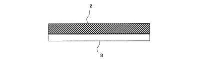
本発明の磁気シールドシートを図面に基づいて説明する。図1(a)及び(b)はそれぞれ本発明の一実施形態を示す断面図である。図1(a)及び(b)に示すように、本発明の磁気シールドシートは、導電性反射層1の片面にのみ磁性体層2を設けるか、あるいは両面に磁性体層2を設けたものである。ここでいう磁性体層2は上述の電磁干渉抑制体と同じものである。導電性反射層1は、磁性金属層、磁性セラミックス層、Fe(鉄)系金属シート、Co系シート、ステンレス、またはFe系金属粉末と結合剤とからなる。導電性反射層1は、少なくとも導電性を有し、電磁波を反射させる層である。導電性反射層1は、導電性材料から成る板、シート、フィルム、箔、織布または不織布であってもよいし、合成樹脂に導電性材料を混合した混合材料から成る板、シート、フィルム、箔、織布または不織布であってもよいし、合成樹脂等から成る基材に導電性材料から成る導電性膜が形成される板、シート、箔、織布またはフィルムであってもよい。アルミニウム、銅、銀、金、鉄、ステンレス等の汎用の導電性金属や磁性金属をそのまま用いても良いし、それらを含有し導電性を発現させたインク、ペースト、接着剤として使用しても良い。導電性反射層1を形成する導電性材料は、金属であってもよいし、カーボン、黒鉛などの金属以外の材料であってもよい。導電性反射層1の材料としては、前記軟磁性粉末で例示した材料を使うことができる。Fe系金属シートには、FeまたはFe系合金の金属箔が例示される。Fe系合金としては、例えば、Al、Mg、Co、Ni、Mo、B、Si、Sr、Nb、Cr等から選ばれる少なくとも1種の元素を有するFe系合金が挙げられる。これらはシート状でもいいし、蒸着されたものでもよい。図1(c)及び(d)はそれぞれ図1(a)及び(b)に示す磁気シールドシートの片面または両面に貼着層3(粘着剤層または接着剤層)を設けたものである。なお、図1(b)及び図1(d)において、一方面のみに磁性体層2を用い、他面は磁性を持たない絶縁層を用いられる構成も取ることができる。
The magnetic shield sheet of this invention is demonstrated based on drawing. 1A and 1B are cross-sectional views showing an embodiment of the present invention. As shown in FIGS. 1A and 1B, the magnetic shield sheet of the present invention has a
Fe系金属シートおよびFe系金属粉末の具体例としては、SPCC(冷間圧延板及び鋼帯(JIS G 3141及びJIS G 3313))、SPCD(冷延圧延鋼板及び帯鋼(JIS G 3141))、SUY(電磁軟鉄)、アモルファス金属箔、溶融亜鉛メッキ鋼板等を挙げることができる。熱処理を付与する、しないにかかわらず使用時に測定した初透磁率が10以上で5,000未満であれば使用可能である。市販品では、例えば、シルバートップ(SF)、Foil Top(東洋鋼鈑株式会社製)等が使用可能である。
これらのFe系金属シートおよびFe系金属粉末は、初透磁率が5,000未満であるのが好ましい。一般に、初透磁率が5,000以上ある材料は、パーマロイやスーパマロイ等に限定され、しかも適正な熱処理を施された際に到達する初透磁率の値である。これらの透磁率は高いものの不安定であり、曲げや応力付加に応じてその磁気特性は大きく劣化することになる。すなわち加工性を犠牲にして高透磁率を達成していることになる。
Specific examples of the Fe-based metal sheet and the Fe-based metal powder include SPCC (cold rolled plate and steel strip (JIS G 3141 and JIS G 3313)), SPCD (cold rolled steel plate and strip steel (JIS G 3141)). , SUY (electromagnetic soft iron), amorphous metal foil, hot-dip galvanized steel sheet and the like. Regardless of whether or not heat treatment is applied, the initial permeability measured at the time of use is 10 or more and less than 5,000. In a commercial item, a silver top (SF), Foil Top (made by Toyo Kohan Co., Ltd.) etc. can be used, for example.
These Fe-based metal sheet and Fe-based metal powder preferably have an initial permeability of less than 5,000. In general, a material having an initial permeability of 5,000 or more is limited to permalloy, supermalloy, and the like, and has an initial permeability value that is reached when an appropriate heat treatment is performed. Although their magnetic permeability is high, they are unstable and their magnetic properties are greatly deteriorated in accordance with bending and stress application. That is, high magnetic permeability is achieved at the expense of workability.
これに対して、本発明の磁気シールドシートは、所望の磁気シールド性を確保できれば、むしろ加工性を重視することを目的としている。つまり磁気シールドシートを打ち抜き、曲げるといった二次加工を施しても性能が安定している。さらに透磁率を上昇させるためのアフターキュア工程を省略しても、所望の磁気シールド性を発現できる。 On the other hand, the magnetic shield sheet of the present invention is intended to emphasize workability as long as desired magnetic shield properties can be secured. In other words, the performance is stable even when a secondary process such as punching and bending the magnetic shield sheet is performed. Furthermore, even if an after-curing step for increasing the magnetic permeability is omitted, desired magnetic shielding properties can be exhibited.
また、導電性反射層1がFeもしくはFe系合金粉末から構成される場合、FeもしくはFe系合金粉末を結合剤に混合し、これをシート状に形成すればよい。このとき、FeもしくはFe系合金粉末は総量に対して約20〜90体積%、好ましくは40〜80体積%である。例えば磁性塗料の性状で使用される。
導電性反射層1の厚さは500μm以下であるのがよく、特に1μm〜100μmが好ましい。導電性反射層1としては、板、箔、塗料等に限定されず、例えばメッシュ、不織布等にメッキしたものを用いても良いし、蒸着、メッキ、吸着法等で固定化したものでも良い。
磁気シールド効果は、KEC法またはアドバンテスト法という公知の方法で、周波数500KHz〜1GHzの範囲で10dBあることが要求される。好ましくは20dB以上である。この周波数域では、磁性体層2の単層構成では所望の磁気シールド効果(10dB)を得ることができず、導電性反射層1を積層することになる。
When the conductive
The thickness of the conductive
The magnetic shield effect is required to be 10 dB in the frequency range of 500 KHz to 1 GHz by a known method called the KEC method or the Advantest method. Preferably it is 20 dB or more. In this frequency range, the desired magnetic shield effect (10 dB) cannot be obtained with the single layer configuration of the
本発明によれば、導電性反射層1と電磁干渉抑制体2を積層することにより絶縁性、磁気シールド性、ノイズ抑制効果を有するシートを得ることが出来る。この磁性体層2は導電性反射層1の防錆処理剤としての効果も持つ。また導電性反射層1は必要に応じて粘着処理や接着処理を施すことができる。
According to the present invention, a sheet having insulating properties, magnetic shielding properties, and noise suppressing effects can be obtained by laminating the conductive
また本発明の電磁干渉抑制体は、難燃剤または難燃助剤が添加されているのが好ましい。これによって電磁干渉抑制体に難燃性が付与されている。例えば携帯電話などのエレクトロニクス機器も、内装するポリマー材料に難燃性を要求されることがある。
このような難燃性を得るための難燃剤としては、特に限定されることはないが、例えばリン化合物、ホウ素化合物、臭素系難燃剤、亜鉛系難燃剤、窒素系難燃剤、水酸化物系難燃剤、金属化合物系難燃剤などを適宜用いることができる。リン化合物としては、リン酸エステル、リン酸チタンなどが挙げられる。ほう素化合物としては、ホウ酸亜鉛などが挙げられる。臭素系難燃剤としては、ヘキサブロモベンゼン、ヘキサブロモシクロドデカン、デカブロモベンジルフェニルエーテル、デカブロモベンジルフェニルオキサイド、テトラブロモビスフェノール、臭化アンモニウムなどが挙げられる。亜鉛系難燃剤としては、炭酸亜鉛、酸化亜鉛若しくはホウ酸亜鉛などが挙げられる。窒素系難燃剤としては、例えばトリアジン化合物、ヒンダードアミン化合物、若しくはメラミンシアヌレート、メラミングアニジン化合物といったようなメラミン系化合物などが挙げられる。水酸化物系難燃剤としては、水酸化マグネシウム、水酸化アルミニウムなどが挙げられる。金属化合物系難燃剤としては、例えば3酸化アンチモン、酸化モリブデン、酸化マンガン、酸化クロム、酸化鉄などが挙げられる。難燃剤および難燃助剤の組合せおよび量は、所望の難燃性を得るために適宜の組合せおよび量が選択されるが、RoHS指令対象物質を除外しても、十分にUL94V0相当の難燃性を得ることは可能である。
Moreover, it is preferable that the electromagnetic interference suppression body of this invention has added the flame retardant or the flame retardant adjuvant. This imparts flame retardancy to the electromagnetic interference suppressor. For example, an electronic device such as a mobile phone may be required to have flame retardancy for an interior polymer material.
The flame retardant for obtaining such flame retardancy is not particularly limited. For example, phosphorus compounds, boron compounds, bromine flame retardants, zinc flame retardants, nitrogen flame retardants, hydroxide series Flame retardants, metal compound flame retardants, and the like can be used as appropriate. Examples of phosphorus compounds include phosphate esters and titanium phosphate. Examples of the boron compound include zinc borate. Examples of brominated flame retardants include hexabromobenzene, hexabromocyclododecane, decabromobenzyl phenyl ether, decabromobenzyl phenyl oxide, tetrabromobisphenol, ammonium bromide and the like. Examples of the zinc-based flame retardant include zinc carbonate, zinc oxide, and zinc borate. Examples of nitrogen-based flame retardants include triazine compounds, hindered amine compounds, or melamine compounds such as melamine cyanurate and melamine anidine compounds. Examples of the hydroxide flame retardant include magnesium hydroxide and aluminum hydroxide. Examples of the metal compound flame retardant include antimony trioxide, molybdenum oxide, manganese oxide, chromium oxide, and iron oxide. As for the combination and amount of the flame retardant and the flame retardant auxiliary, an appropriate combination and amount are selected in order to obtain the desired flame retardancy, but even when excluding the substances subject to the RoHS directive, the flame retardant equivalent to UL94V0 is sufficiently obtained. It is possible to get sex.
本実施形態では、重量比において、結合剤を100に対して、臭素系難燃剤を20、三酸化アンチモンを10、リン酸エステルを14の比で、それぞれ添加することによって、UL94難燃試験においてV0相当の難燃性を得ることができる。電磁干渉抑制体は、このような物品を構成する素材として、または物品に装着して好適に用いることができる。例えば航空機、船舶、自動車および車両内の装置など、燃焼およびこれに伴うガスの発生を防止及び抑制したい空間などで用いられる物品に装着するなどして、好適に用いることができる。 In this embodiment, in the UL94 flame retardant test, the binder is 100, the bromine-based flame retardant is 20, the antimony trioxide is 10 and the phosphate ester is 14 in a weight ratio. Flame retardance equivalent to V0 can be obtained. The electromagnetic interference suppressor can be suitably used as a material constituting such an article or by being attached to the article. For example, it can be suitably used by being mounted on an article used in a space or the like where it is desired to prevent and suppress combustion and the generation of gas accompanying it, such as an aircraft, a ship, an automobile, and a device in a vehicle.
本発明の電磁干渉抑制体は、結合剤、軟磁性粉末以外にも前述の添加剤に限定されることなく、無機系充填材、微粉末、ゲル状物質など必要に応じて一切添加物を加えることができる。加えた添加剤は本発明でいう充填剤である。 The electromagnetic interference suppressor of the present invention is not limited to the above-mentioned additives other than the binder and soft magnetic powder, and any additives such as inorganic fillers, fine powders, and gel substances are added as necessary. be able to. The added additive is a filler referred to in the present invention.
本発明の電磁干渉抑制体は、少なくとも一方の表面部が、粘着性または接着性を有している。本実施形態では、貼着層(粘着剤層または接着剤層)を有しており、これによって図1(c)(d)、図2に示すように、電磁干渉抑制体2の厚み方向の片面に貼着層3を有している。電磁干渉抑制体2は、貼着層3の粘着性または接着性による結合力によって、物品に貼着することができる。したがって電磁干渉抑制体2は、例えば金属製部材に貼着することによって、アンテナ素子と金属製部材との間に、容易に設けることができる。電磁干渉抑制体2は、厚み方向一方側がアンテナ素子側に配置され、厚み方向他方側が金属製部材側に配置されて設けられる。貼着材としては、例えば日東電工社製No.5000NSが用いられる。
As for the electromagnetic interference suppression body of this invention, at least one surface part has adhesiveness or adhesiveness. In this embodiment, it has a sticking layer (adhesive layer or adhesive layer), and as a result, as shown in FIGS. 1 (c) and 1 (d), FIG. The
本発明の電磁干渉抑制体は、厚さが1μm〜2mmの(薄型磁性)シート状の形態で使用するのが好ましい。より好ましくは厚さが10μm〜1mmのシート状である。一般にシート状の場合には、内部に(扁平)軟磁性粉末が凝集して、エアーや溶剤の揮発ガスの抜け道に自由度がなくなり、空隙がそのままシート中に残り易いのに対して、本発明では、シート中の残量エアーを殆どなくしている。 The electromagnetic interference suppressor of the present invention is preferably used in the form of a (thin magnetic) sheet having a thickness of 1 μm to 2 mm. More preferably, it is a sheet having a thickness of 10 μm to 1 mm. In general, in the case of a sheet, the (flat) soft magnetic powder aggregates in the inside, and there is no degree of freedom in the passage of air and solvent volatile gases, and voids tend to remain in the sheet. Then, the remaining air in the seat is almost eliminated.
本発明の電磁干渉抑制体は、前記(扁平)軟磁性粉末と結合剤とを含有した磁性塗料を、例えば支持体上にブレード等にて塗布、乾燥し、ついでこの支持体から分離(剥離)させることで得られる。 The electromagnetic interference suppressor of the present invention is a magnetic paint containing the above (flat) soft magnetic powder and a binder, for example, applied to a support with a blade or the like, dried, and then separated (peeled) from the support. Can be obtained.
前記磁性塗料の調製には、(扁平)軟磁性粉末および結合剤を溶解または分散させるための溶剤を使用する。このような溶剤としては、特に限定されるものではないが、例えばアセトン、メチルエチルケトン(MEK)、メチルイソブチルケトン、シクロヘキサノン等のケトン類、メタノール、エタノール、プロパノール、ブタノール、イソプロピルアルコール等のアルコール類、酢酸メチル、酢酸エチル、酢酸プロピル、酢酸ブチル、乳酸エチル、エチルグリコールアセテート等のエステル類、ジエチレングリコールジメチルエーテル、2−エトキシエタノール、テトラヒドロフラン、ジオキサン等のエーテル類、ベンゼン、トルエン、キシレン等の芳香族炭化水素化合物、メチレンクロライド、エチレンクロライド、四塩化炭素、クロロフォルム、クロロベンゼン等のハロゲン化炭化水素化合物などを用いることができる。これらの溶剤は、それぞれ単独で使用できるほか、2種以上をブレンドして用いてもよい。 For the preparation of the magnetic paint, a (flat) soft magnetic powder and a solvent for dissolving or dispersing the binder are used. Examples of such solvents include, but are not limited to, ketones such as acetone, methyl ethyl ketone (MEK), methyl isobutyl ketone, and cyclohexanone, alcohols such as methanol, ethanol, propanol, butanol, and isopropyl alcohol, and acetic acid. Esters such as methyl, ethyl acetate, propyl acetate, butyl acetate, ethyl lactate and ethyl glycol acetate, ethers such as diethylene glycol dimethyl ether, 2-ethoxyethanol, tetrahydrofuran and dioxane, and aromatic hydrocarbon compounds such as benzene, toluene and xylene , Halogenated hydrocarbon compounds such as methylene chloride, ethylene chloride, carbon tetrachloride, chloroform, chlorobenzene, and the like can be used. These solvents can be used alone or in combination of two or more.
前記磁性塗料は、前記溶剤を結合剤100重量部に対して1000重量部以下、好ましくは100〜800重量部の割合で含有するのがよい。これに対し、溶剤の含有量が1000重量部を超えると、シート中に残留エアーが残るので好ましくない。
前記塗料調製のための分散および混練装置としては、例えばニーダ、アジタ、ボールミル、サウンドミル、ロールミル、エクストルーダー、ホモジナイザ、超音波分散機、2軸遊星式混練機等を用いることができる。これら分散および混合装置のうち、特に(扁平)軟磁性粉末を破壊、歪みを与えない、アジタ、ボールミル、ロールミル、ホモジナイザ、超音波分散機、2軸遊星式混練機等が好ましい。
The magnetic paint contains the solvent in an amount of 1000 parts by weight or less, preferably 100 to 800 parts by weight, based on 100 parts by weight of the binder. On the other hand, if the solvent content exceeds 1000 parts by weight, residual air remains in the sheet, which is not preferable.
As the dispersion and kneading apparatus for preparing the coating material, for example, a kneader, an agitator, a ball mill, a sound mill, a roll mill, an extruder, a homogenizer, an ultrasonic disperser, a two-axis planetary kneader, or the like can be used. Among these dispersing and mixing apparatuses, an agitator, a ball mill, a roll mill, a homogenizer, an ultrasonic disperser, a twin-shaft planetary kneader, etc. that do not break or give distortion to (flat) soft magnetic powder are particularly preferable.
前記支持体としては、特に限定されるものではなく、例えば紙、ポリオレフィン等の高分子樹脂をラミネートした紙、紙、高分子、樹脂、布、不織布、金属、金属処理(蒸着、メッキ)したもの等が挙げられる。これらのうち、薄くて強度が有る高分子樹脂が好ましく、この高分子樹脂としては、例えばポリエチレンテレフタレート、ポリエチレン−2、6−ナフタレート等のポリエステル類、ポリエチレン、ポリプロピレン等のポリオレフィン類、これらポリオレフィン類の水素の一部または全部をフッ素樹脂で置換したフッ素樹脂、セルローストリアセテート、セルロースダイアセテート等のセルロース誘導体、ポリ塩化ビニル等のビニル系樹脂、ポリ塩化ビニリデン等のビニリデン樹脂、ポリカーボネート、ポリフェニレンサルファイド、ポリアミドイミド、ポリイミド等が挙げられる。これらの高分子樹脂表面は、シリコーン樹脂等の離型剤で剥離処理を施しているのが、電磁干渉抑制体を簡単に剥離することができるうえで好ましい。また、これらの高分子樹脂は、厚さ1μm〜100mm程度のフィルム状であるのがよい。この支持体は、剥離して製品から除去されても良いし、最終製品として電磁干渉抑制体と一体に供せられるものでも良い。剥離すれば薄型化に寄与できるし、一体化すれば電磁干渉抑制体の剛性向上やスリット等の加工性向上に寄与することになる。 The support is not particularly limited. For example, paper, paper laminated with a polymer resin such as polyolefin, paper, polymer, resin, cloth, non-woven fabric, metal, metal-treated (vapor deposition, plating) Etc. Among these, a thin and strong polymer resin is preferable, and examples of the polymer resin include polyesters such as polyethylene terephthalate, polyethylene-2 and 6-naphthalate, polyolefins such as polyethylene and polypropylene, and polyolefins such as these. Fluorine resin in which part or all of hydrogen is replaced with fluorine resin, cellulose derivatives such as cellulose triacetate and cellulose diacetate, vinyl resins such as polyvinyl chloride, vinylidene resins such as polyvinylidene chloride, polycarbonate, polyphenylene sulfide, and polyamideimide And polyimide. The surface of these polymer resins is preferably peeled with a release agent such as a silicone resin because the electromagnetic interference suppressor can be easily peeled off. These polymer resins are preferably in the form of a film having a thickness of about 1 μm to 100 mm. The support may be peeled off and removed from the product, or the support may be provided integrally with the electromagnetic interference suppressor as a final product. If it peels, it can contribute to thickness reduction, and if it integrates, it will contribute to the improvement of the rigidity of an electromagnetic interference suppression body, and workability improvement, such as a slit.
前記支持体上に磁性塗料を塗布する方法は、特に限定されるものではなく、例えばエアドクターコート、ブレードコート、ワイアバーコート、エアナイフコート、スクイズコート、含浸コート、リバースロールコート、トランスファロールコート、グラビアコート、キスコート、キャストコート、エクストルージョンコート、ダイコート、スピンコート等の従来の方法は、いずれも採用可能である。 The method for applying the magnetic paint on the support is not particularly limited, and for example, air doctor coat, blade coat, wire bar coat, air knife coat, squeeze coat, impregnation coat, reverse roll coat, transfer roll coat, Any of conventional methods such as gravure coating, kiss coating, cast coating, extrusion coating, die coating, and spin coating can be employed.
また、前記磁性塗料を支持材上に塗工中または塗工後に磁場を加えてもよい。これにより得られる電磁干渉抑制体は、扁平軟磁性粉末を面内方向に配向させているので、軟磁性粉末をより高密度に充填することができる。扁平軟磁性粉末を面内方向に配向させるには、例えば塗工面の上方または下方に永久磁石を設置し、垂直方向(シートの厚さ方向)に磁場をくわえる。磁場の強さ(磁束密度)は、溶剤に溶解または分散している結合剤、扁平軟磁性粉末の種類により異なるが、一般に0.01〜1テスラの範囲が選ばれる。 Further, a magnetic field may be applied during or after coating the magnetic coating material on the support material. Since the electromagnetic interference suppressing body obtained in this way has the flat soft magnetic powder oriented in the in-plane direction, the soft magnetic powder can be filled at a higher density. In order to orient the flat soft magnetic powder in the in-plane direction, for example, a permanent magnet is installed above or below the coated surface, and a magnetic field is added in the vertical direction (the thickness direction of the sheet). The strength of the magnetic field (magnetic flux density) varies depending on the type of the binder and flat soft magnetic powder dissolved or dispersed in the solvent, but is generally in the range of 0.01 to 1 Tesla.
支持材上に塗布、乾燥し、ついで所定の形状にするために切り落とされた端材は、回収して支持体を剥離し、例えば前記磁性塗料に加えることで、この塗料中の溶剤に簡単に溶解または分散するので、再利用することができる。 The end material that has been applied to the support material, dried, and then cut off to form a predetermined shape is collected, peeled off the support, and added to the magnetic paint, for example. Since it is dissolved or dispersed, it can be reused.
本発明の電磁干渉抑制体は、テレビなどの家庭電気製品、パソコンなどのコンピューター、携帯電話などの移動体通信機器、医療機器など各種の電子機器に使用され、これら電子機器から放出される不要電磁波が他の電子機器や電子部品、回路基板に影響を与えて誤作動を発生させるのを抑制することができる。具体的には、前記の電子機器類の内部または周辺部に配置されることにより、不要電磁波の干渉によって生じる電磁障害を効果的に抑制する。またSAR対策部品として用いることも可能である。シート形態の磁気シールド材として簡便に用いることもできる。このため、本発明の電磁干渉抑制体の使用形態としては、例えばシート状の電磁干渉抑制体を適宜切り取り、機器のノイズ源近傍に貼り付けたり、あるいは機器のノイズ源または近傍に前記のように塗布するなどして電磁干渉抑制体を形成するなどして使用される。具体的には電子機器内のFPC回路の電磁シールド対策として貼着されることがある。 The electromagnetic interference suppressor of the present invention is used in various electronic devices such as home electric products such as televisions, computers such as personal computers, mobile communication devices such as mobile phones, and medical devices, and unnecessary electromagnetic waves emitted from these electronic devices. Can suppress other electronic devices, electronic components, and circuit boards from causing malfunctions. Specifically, electromagnetic interference caused by interference of unnecessary electromagnetic waves is effectively suppressed by being disposed inside or around the electronic devices. It can also be used as a SAR countermeasure component. It can also be conveniently used as a magnetic shield material in the form of a sheet. For this reason, as a usage form of the electromagnetic interference suppressor of the present invention, for example, a sheet-like electromagnetic interference suppressor is appropriately cut out and pasted near the noise source of the device, or as described above near the noise source of the device. It is used, for example, by forming an electromagnetic interference suppressor by coating. Specifically, it may be affixed as a countermeasure against electromagnetic shielding of FPC circuits in electronic equipment.
以下、実施例および比較例を挙げて本発明の電磁干渉抑制体を詳細に説明するが、本発明は以下の実施例に限定されるものではない。 Hereinafter, although an electromagnetic interference suppression object of the present invention is explained in detail using an example and a comparative example, the present invention is not limited to the following examples.
以下の実施例および比較例で用いた材料は次の通りである。
・ ウレタン樹脂:日本ポリウレタン工業株式会社製のニッポラン
・ 扁平Fe−Ni−Cr−Si:三菱マテリアル株式会社製のJEM粉
塗液作成に用いた溶剤はトルエンを主とした混合溶剤である。
貯蔵弾性率(E’)は、セイコーインスルメンツ株式会社製DMA(動的粘弾性測定装置)により測定した。実施例で用いた樹脂および電磁干渉抑制体について貯蔵弾性率(E')を測定した結果は、それぞれ図3、4に示した。なお、図3では比較例1は1.0×10⁶以下であるのでグラフには表れていない。軟化温度は、同DMA及びシート状サンプル(JIS 2号ダンベル形状)に一定荷重の重りを与え、恒温槽内で5℃/分の昇温を行い、シート状サンプルの伸びが最大となった温度により決定している。
The materials used in the following examples and comparative examples are as follows.
-Urethane resin: NIPPOLAN manufactured by Nippon Polyurethane Industry Co., Ltd.-Flat Fe-Ni-Cr-Si: JEM powder manufactured by Mitsubishi Materials Co., Ltd. The solvent used for preparing the coating liquid is a mixed solvent mainly composed of toluene.
The storage elastic modulus (E ′) was measured by DMA (dynamic viscoelasticity measuring device) manufactured by Seiko Instruments Inc. The results of measuring the storage elastic modulus (E ′) of the resin and electromagnetic interference suppressor used in the examples are shown in FIGS. In FIG. 3, since Comparative Example 1 is 1.0 × 10 6 or less, it does not appear in the graph. The softening temperature is a temperature at which the DMA and the sheet-like sample (JIS No. 2 dumbbell shape) are given a constant load weight, heated at 5 ° C./min in a thermostatic bath, and the elongation of the sheet-like sample is maximized. It is decided by.
[実施例1〜4および比較例1、2 ]
<電磁干渉抑制シートの作製>
表1に示す乾燥時にシートの軟磁性金属粉の含有量が40体積%となるべく結合剤およびその他の充填剤、そして溶剤を加えて磁性塗料を作成し、ドクターブレード法にてPET(ポリエチレンテレフタレート、剥離支持体)上に塗工および乾燥し、加圧処理することなくシート成形を行った。ついで、剥離支持体をはがし、厚さ100μmの電磁干渉抑制シートを得た。表1に於いて軟磁性金属粉は同一のものを同じ量だけ使っている。それぞれ異なるのは結合剤として用いたポリマーの性状である。表1の中で実施例3は、実施例1の樹脂に硬化剤(TDI系イソシアナート組成物)を加え80℃で72時間エージングを行って架橋を施したものである。得られた電磁干渉抑制シートについて材料定数(μ’、μ”、ε’、ε”)、比重、1GHzの伝送損失および100MHzの透過損失をそれぞれ測定した。その結果を表1に併せて示す。上記測定は室温25℃で行った。実施例に用いた結合剤はウレタン樹脂の基本構造は同じであるが、数平均分子量(Mn)、重量平均分子量(Mw)、分子量分布(Mw/Mn)、ハードセグメントとソフトセグメントの比率(表中示さず)を変化させている。この結果として結合剤の性状のうち、貯蔵弾性率(E’)及び軟化点が変わり、これらのシート性能への影響をみている。
[Examples 1 to 4 and Comparative Examples 1 and 2]
<Production of electromagnetic interference suppression sheet>
A magnetic paint was prepared by adding a binder and other fillers and a solvent so that the content of the soft magnetic metal powder in the sheet was 40% by volume at the time of drying shown in Table 1, and PET (polyethylene terephthalate, It was coated and dried on a release support), and sheet forming was performed without pressure treatment. Next, the release support was peeled off to obtain an electromagnetic interference suppression sheet having a thickness of 100 μm. In Table 1, the same amount of soft magnetic metal powder is used. What is different is the properties of the polymer used as the binder. In Table 1, Example 3 is obtained by adding a curing agent (TDI isocyanate composition) to the resin of Example 1 and performing aging at 80 ° C. for 72 hours to perform crosslinking. The obtained electromagnetic interference suppression sheet was measured for material constants (μ ′, μ ″, ε ′, ε ″), specific gravity, 1 GHz transmission loss, and 100 MHz transmission loss. The results are also shown in Table 1. The said measurement was performed at room temperature 25 degreeC. The binder used in the examples has the same basic structure of urethane resin, but the number average molecular weight (Mn), weight average molecular weight (Mw), molecular weight distribution (Mw / Mn), ratio of hard segment to soft segment (Table (Not shown). As a result, among the properties of the binder, the storage elastic modulus (E ′) and the softening point are changed, and the influence on the sheet performance is observed.
<分子量の測定方法>
分子量および分子量分布は、島津製作所製ゲルパーミュエーションクロマトグラフィ(GPC)により、ポリスチレンを標準物質とし、重量平均分子量(Mw)、数平均分子量(Mn)を測定した。分子量分布は得られたMw/Mnにより算出した。GPCの測定条件は以下の通りである。溶媒:テトラヒドロフラン、溶媒流量:1mL/分、温度:40℃、サンプル濃度:3mg/mL、サンプル注入量:50μL、検出器:RI。高分子量のウレタン樹脂には、展開溶媒としてDMFを使用することもある。
<Measurement method of molecular weight>
The molecular weight and molecular weight distribution were measured by gel permeation chromatography (GPC) manufactured by Shimadzu Corporation, using polystyrene as a standard substance, and weight average molecular weight (Mw) and number average molecular weight (Mn). The molecular weight distribution was calculated from the obtained Mw / Mn. The measurement conditions for GPC are as follows. Solvent: tetrahydrofuran, solvent flow rate: 1 mL / min, temperature: 40 ° C., sample concentration: 3 mg / mL, sample injection amount: 50 μL, detector: RI. For high molecular weight urethane resins, DMF may be used as a developing solvent.
<伝送損失の測定方法>
伝送損失の測定にはインピーダンスZ=50Ωのマイクロストリップラインを使用した。マイクロストリップライン線路は、面実装部品の実装に適した構造と作成のしやすさによって、広く使われている近傍ノイズの伝送損失測定方法である。図5は、使用したマイクロストリップラインの形状を示す。このものは、絶縁体基板51の表面に直線状の導体路52を設け、この導体路52上に電磁干渉抑制シート54を載置したものである。導体路52の両端はネットワークアナライザー(図示せず)に接続される。そして、矢印Aで示す入射波に対して、電磁波吸収材料54の載置部位からの反射量(dB)(矢印S11で示す)および透過量(dB)(矢印S21で示す)を測定し、それらの差をロス量とし、伝送損失(吸収量)を下記式から求めた。

A microstrip line with impedance Z = 50Ω was used for measurement of transmission loss. The microstrip line is a method for measuring transmission loss of nearby noise that is widely used due to its structure suitable for mounting surface-mounted components and ease of production. FIG. 5 shows the shape of the microstrip line used. In this device, a
<透過損失の測定方法>
電磁干渉抑制シートを介して、間隔1mmに配置した発振用および受信用ループアンテナにおいて、発振アンテナから放射した電磁波が受信アンテナに到達する度合いをネットワークアナライザーにより測定した。この測定により放射ノイズに対する電磁干渉抑制シートの減衰効果を評価することが可能となる。
<Measurement method of transmission loss>
The degree to which the electromagnetic waves radiated from the oscillation antenna reached the reception antenna in the oscillation and reception loop antennas arranged at intervals of 1 mm through the electromagnetic interference suppression sheet was measured by a network analyzer. This measurement makes it possible to evaluate the attenuation effect of the electromagnetic interference suppression sheet against radiation noise.
<材料定数の評価方法>
電磁干渉抑制体の材料定数は、複素比透磁率の実数部μ’および虚数部μ”、複素比誘電率の実数部ε’および虚数部ε”を含む。測定は材料をリング加工(φ7×φ3)して同軸管法で測定した。使用した機器は、周波数が1MHz〜1.8GHzに対してはマテリアルアナライザー(アジレント社製E4991A)である。
なお、表1において、例えば「2.32E+07」は2.32×10⁷を意味している。
これに対して、本発明の範囲内である実施例1〜4は、実比重が高く、透磁率が高く、伝送損失、透過損失が高い結果を示した。なお、実施例4では、温度55℃での結合剤の貯蔵弾性率E’は107Pa以下であるが、乾燥時の乾燥温度(25℃)での貯蔵弾性率E’が107Pa以上であるため、結合剤の凝集力は強く、溶剤排出がなされ実比重が高くなった。
貯蔵弾性率に関しては、表1に示すように、25℃と55℃の2点を評価していた。これは塗工シートを室温乾燥する場合が、ポリマーの25℃の貯蔵弾性率が当てはまり、塗工シートを強制乾燥する場合が、ポリマーの55℃の貯蔵弾性率が当てはまる関係となる。それぞれの乾燥温度において、ポリマーの溶剤排出能力を評価しており、それぞれの温度で高い数値を取るほど、ボイドを発生することが少なく乾燥シートを得ることができる。この溶剤排出能力を高めるためには、溶剤乾燥条件に於けるポリマーの凝集力を高めることが必要であり、本発明では分子量および分子量分布と貯蔵弾性率E’に注目して適正な範囲を求めた。
実施例3は実施例1の樹脂を用い、架橋剤を添加して磁性塗料としたものである。磁性塗料の段階では架橋反応は起きず、実施例1とほぼ同じ性状の塗液として取り扱うことができる。乾燥時あるいは乾燥後に三次元架橋を施すことにより分子量及び分子量分布は実施例1よりも向上しており、ポリマーの凝集力も貯蔵弾性率も向上できている。
<Evaluation method of material constant>
The material constants of the electromagnetic interference suppressor include a real part μ ′ and an imaginary part μ ″ of complex relative permeability, and a real part ε ′ and an imaginary part ε ″ of complex relative permittivity. The measurement was carried out by ring processing (φ7 × φ3) of the material and the coaxial tube method. The equipment used is a material analyzer (E4991A manufactured by Agilent) for frequencies of 1 MHz to 1.8 GHz.
In Table 1, for example, “2.32E + 07” means 2.32 × 10 7 .
On the other hand, Examples 1-4 which are within the scope of the present invention showed high actual specific gravity, high magnetic permeability, and high transmission loss and transmission loss. In Example 4, the storage elastic modulus E ′ of the binder at a temperature of 55 ° C. is 10 7 Pa or less, but the storage elastic modulus E ′ at the drying temperature (25 ° C.) during drying is 10 7 Pa or more. Therefore, the cohesive strength of the binder was strong, the solvent was discharged, and the actual specific gravity increased.
Regarding storage elastic modulus, as shown in Table 1, two points of 25 ° C. and 55 ° C. were evaluated. When the coated sheet is dried at room temperature, the storage elastic modulus of 25 ° C. of the polymer is applied, and when the coated sheet is forcedly dried, the storage elastic modulus of 55 ° C. of the polymer is applied. The solvent discharging ability of the polymer is evaluated at each drying temperature, and the higher the value at each temperature, the less the voids are generated, and the dried sheet can be obtained. In order to increase the solvent discharging capacity, it is necessary to increase the cohesive strength of the polymer under the solvent drying conditions. In the present invention, an appropriate range is obtained by paying attention to the molecular weight, molecular weight distribution and storage elastic modulus E ′. It was.
Example 3 uses the resin of Example 1 and adds a cross-linking agent to make a magnetic paint. The crosslinking reaction does not occur at the magnetic coating stage, and it can be handled as a coating liquid having substantially the same properties as in Example 1. By performing three-dimensional crosslinking during or after drying, the molecular weight and molecular weight distribution are improved as compared with Example 1, and the cohesive strength and storage elastic modulus of the polymer can be improved.
本発明の電磁干渉抑制体は、100MHzおよび1GHzの周波数またその間の周波数にて、複素比透磁率の実数部μ’が高く、且つ複素比透磁率の虚数部μ”が高くなる関係となる。表1に示したように、本発明の電磁干渉抑制体(実施例1〜4)は、μ’が高いため磁界を集めやすく、且つμ”が高いことにより集めた磁束を損失し易いという性質を有しているといえる。そして複素比誘電率の虚数部蜚が低い(500以下)ことから、電磁波干渉抑制体自体の導電率が低く、高い抵抗率を示すことが判明した。それは電磁波干渉抑制体自身に電磁波を反射(遮蔽)しないことを意味している。 The electromagnetic interference suppressor of the present invention has a relationship in which the real part μ ′ of the complex relative permeability is high and the imaginary part μ ″ of the complex relative permeability is high at frequencies of 100 MHz and 1 GHz or between them. As shown in Table 1, the electromagnetic interference suppressor (Examples 1 to 4) of the present invention has a property that it is easy to collect a magnetic field because μ ′ is high, and it is easy to lose magnetic flux collected due to high μ ″. It can be said that it has. And since the imaginary part 蜚 of the complex relative permittivity is low (500 or less), it has been found that the electromagnetic interference suppression body itself has low conductivity and high resistivity. That means that the electromagnetic wave interference suppressor itself does not reflect (shield) the electromagnetic wave.
[実施例5,6]
<架橋した電磁干渉抑制シートの作製>
表2に示す配合割合にした他は、実施例3と同じ材料を使用し、実施例3と同様に加圧処理することなく硬化剤にて結合剤を架橋させて厚さ100μmの電磁干渉抑制シートを得た。得られた電磁干渉抑制シートについて材料定数(μ’、μ”、ε’、ε”)、比重、1GHzの伝送損失および100MHzの透過損失をそれぞれ測定した。また、室温下で各実施例のシートを90°に折り曲げたときの亀裂発生の有無を目視にて観察した。それらの結果を表2に併せて示す。表2には、実施例3の試験結果も示している。
また、実施例3,5,6の各電磁干渉抑制シートを50℃、湿度85%の雰囲気下に500時間放置したときの、材料定数(μ’、μ”、ε’、ε”)、比重、1GHzの伝送損失および100MHzの透過損失、さらに90°折り曲げ時の亀裂発生の有無をそれぞれ測定した。それらの結果を表3に併せて示す。
<Production of crosslinked electromagnetic interference suppression sheet>
Except for the blending ratio shown in Table 2, the same material as in Example 3 was used, and the electromagnetic interference suppression of 100 μm in thickness was performed by crosslinking the binder with a curing agent without applying pressure as in Example 3. A sheet was obtained. The obtained electromagnetic interference suppression sheet was measured for material constants (μ ′, μ ″, ε ′, ε ″), specific gravity, 1 GHz transmission loss, and 100 MHz transmission loss. Further, the presence or absence of cracks when the sheet of each example was bent at 90 ° at room temperature was visually observed. The results are also shown in Table 2. Table 2 also shows the test results of Example 3.
Further, the material constants (μ ′, μ ″, ε ′, ε ″), specific gravity when the electromagnetic interference suppression sheets of Examples 3, 5, and 6 were left in an atmosphere of 50 ° C. and 85% humidity for 500 hours. The transmission loss of 1 GHz, the transmission loss of 100 MHz, and the presence or absence of cracks when bent at 90 ° were measured. The results are also shown in Table 3.
1 導電性反射層
2 電磁干渉抑制体
3 貼着層
54 電磁干渉抑制シート
DESCRIPTION OF
Claims (11)
Priority Applications (1)
| Application Number | Priority Date | Filing Date | Title |
|---|---|---|---|
| JP2007160569A JP2008021990A (en) | 2006-06-16 | 2007-06-18 | Electromagnetic interference suppressor and electromagnetic interference suppression method |
Applications Claiming Priority (2)
| Application Number | Priority Date | Filing Date | Title |
|---|---|---|---|
| JP2006168184 | 2006-06-16 | ||
| JP2007160569A JP2008021990A (en) | 2006-06-16 | 2007-06-18 | Electromagnetic interference suppressor and electromagnetic interference suppression method |
Publications (1)
| Publication Number | Publication Date |
|---|---|
| JP2008021990A true JP2008021990A (en) | 2008-01-31 |
Family
ID=39077693
Family Applications (1)
| Application Number | Title | Priority Date | Filing Date |
|---|---|---|---|
| JP2007160569A Pending JP2008021990A (en) | 2006-06-16 | 2007-06-18 | Electromagnetic interference suppressor and electromagnetic interference suppression method |
Country Status (1)
| Country | Link |
|---|---|
| JP (1) | JP2008021990A (en) |
Cited By (31)
| Publication number | Priority date | Publication date | Assignee | Title |
|---|---|---|---|---|
| EP2070723A4 (en) * | 2006-09-28 | 2010-03-24 | Dainippon Printing Co Ltd | Decorative sheet |
| JP2011181815A (en) * | 2010-03-03 | 2011-09-15 | Shuho:Kk | Electromagnetic wave absorber |
| JP2012064777A (en) * | 2010-09-16 | 2012-03-29 | Mitsubishi Electric Corp | Noise filter, cable with noise filter, and printed wiring board with noise filter |
| JP2012124355A (en) * | 2010-12-09 | 2012-06-28 | Toray Ind Inc | Paste composition and magnetic body composition using it |
| JP2012146869A (en) * | 2011-01-13 | 2012-08-02 | Alps Electric Co Ltd | Magnetic sheet and method for manufacturing magnetic sheet |
| JP2012238764A (en) * | 2011-05-12 | 2012-12-06 | Sumitomo Bakelite Co Ltd | Composite resin composition and molding exhibiting excellent electromagnetic wave shielding properties |
| JP2013229290A (en) * | 2012-03-30 | 2013-11-07 | Molex Inc | Connector with sheet |
| JP2013229541A (en) * | 2011-06-17 | 2013-11-07 | Toda Kogyo Corp | Electromagnetic wave interference suppressor |
| KR20160013024A (en) * | 2013-05-27 | 2016-02-03 | 닛토덴코 가부시키가이샤 | Soft magnetic resin composition, soft magnetic adhesive film, soft magnetic film laminate circuit board, and position detection device |
| JP2016146401A (en) * | 2015-02-06 | 2016-08-12 | 住友ベークライト株式会社 | Electromagnetic wave shielding film, and electronic component mounting board |
| EP2963657A4 (en) * | 2013-02-26 | 2016-11-16 | Nitto Denko Corp | FLEXIBLE MAGNETIC FILM |
| JP2017022319A (en) * | 2015-07-14 | 2017-01-26 | 住友ベークライト株式会社 | Electromagnetic wave shielding film and electronic component mounting board |
| US20170110231A1 (en) * | 2014-05-29 | 2017-04-20 | Nitto Denko Corporation | Soft magnetic resin composition and soft magnetic film |
| WO2017082318A1 (en) * | 2015-11-12 | 2017-05-18 | 住友ベークライト株式会社 | Electromagnetic wave absorbing laminate, case and method for using electromagnetic wave absorbing laminate |
| JP2019071426A (en) * | 2016-11-04 | 2019-05-09 | マクセルホールディングス株式会社 | Electromagnetic wave absorbing sheet |
| JP2019075571A (en) * | 2016-11-04 | 2019-05-16 | マクセルホールディングス株式会社 | Electromagnetic wave-absorbing sheet |
| CN110741505A (en) * | 2017-06-14 | 2020-01-31 | 丰田自动车株式会社 | Antenna device |
| US10662316B2 (en) | 2016-03-25 | 2020-05-26 | Fuji Polymer Industries Co., Ltd. | Magneto-rheological elastomer composition, method for producing same, and vibration absorbing device including same |
| JPWO2020230448A1 (en) * | 2019-05-14 | 2020-11-19 | ||
| CN113239530A (en) * | 2021-04-28 | 2021-08-10 | 浙江威星智能仪表股份有限公司 | Magnetic ring selection method suitable for low-power communication equipment |
| JPWO2022050424A1 (en) * | 2020-09-07 | 2022-03-10 | ||
| JP2022066622A (en) * | 2020-10-19 | 2022-05-02 | Tdk株式会社 | Magnetic shield sheet and communication cable equipped with it |
| CN117397378A (en) * | 2021-05-31 | 2024-01-12 | 富士胶片株式会社 | Electromagnetic wave shielding materials, electronic parts and electronic equipment |
| WO2024203626A1 (en) * | 2023-03-30 | 2024-10-03 | 戸田工業株式会社 | Soft magnetic compound |
| US12142834B2 (en) | 2019-05-14 | 2024-11-12 | Fujifilm Corporation | Radio wave absorber |
| US12160984B2 (en) | 2019-05-14 | 2024-12-03 | Fujifilm Corporation | Radio wave absorber |
| US12260977B2 (en) | 2018-08-28 | 2025-03-25 | Fujifilm Corporation | Powder of magnetoplumbite-type hexagonal ferrite, method for producing the same, and radio wave absorber |
| US12272875B2 (en) | 2019-05-14 | 2025-04-08 | Fujifilm Corporation | Radio wave absorber |
| CN120572622A (en) * | 2025-06-19 | 2025-09-02 | 成都能斯特新材料科技有限公司 | A process control method for improving warping deformation during cast film printing |
| US12426224B2 (en) | 2019-08-09 | 2025-09-23 | Fujifilm Corporation | Radio wave absorbing composition and radio wave absorber |
| WO2026160405A1 (en) * | 2025-01-24 | 2026-07-30 | マクセル株式会社 | Shielded cable |
Citations (2)
| Publication number | Priority date | Publication date | Assignee | Title |
|---|---|---|---|---|
| JP2000196281A (en) * | 1998-11-12 | 2000-07-14 | Sony Corp | Electromagnetic wave absorber, method of manufacturing the same, and electronic device |
| WO2006059771A1 (en) * | 2004-12-03 | 2006-06-08 | Nitta Corporation | Electromagnetic interference inhibitor, antenna device and electronic communication apparatus |
-
2007
- 2007-06-18 JP JP2007160569A patent/JP2008021990A/en active Pending
Patent Citations (2)
| Publication number | Priority date | Publication date | Assignee | Title |
|---|---|---|---|---|
| JP2000196281A (en) * | 1998-11-12 | 2000-07-14 | Sony Corp | Electromagnetic wave absorber, method of manufacturing the same, and electronic device |
| WO2006059771A1 (en) * | 2004-12-03 | 2006-06-08 | Nitta Corporation | Electromagnetic interference inhibitor, antenna device and electronic communication apparatus |
Cited By (43)
| Publication number | Priority date | Publication date | Assignee | Title |
|---|---|---|---|---|
| EP2070723A4 (en) * | 2006-09-28 | 2010-03-24 | Dainippon Printing Co Ltd | Decorative sheet |
| JP2011181815A (en) * | 2010-03-03 | 2011-09-15 | Shuho:Kk | Electromagnetic wave absorber |
| JP2012064777A (en) * | 2010-09-16 | 2012-03-29 | Mitsubishi Electric Corp | Noise filter, cable with noise filter, and printed wiring board with noise filter |
| JP2012124355A (en) * | 2010-12-09 | 2012-06-28 | Toray Ind Inc | Paste composition and magnetic body composition using it |
| JP2012146869A (en) * | 2011-01-13 | 2012-08-02 | Alps Electric Co Ltd | Magnetic sheet and method for manufacturing magnetic sheet |
| JP2012238764A (en) * | 2011-05-12 | 2012-12-06 | Sumitomo Bakelite Co Ltd | Composite resin composition and molding exhibiting excellent electromagnetic wave shielding properties |
| JP2013229541A (en) * | 2011-06-17 | 2013-11-07 | Toda Kogyo Corp | Electromagnetic wave interference suppressor |
| JP2013229290A (en) * | 2012-03-30 | 2013-11-07 | Molex Inc | Connector with sheet |
| EP2963657A4 (en) * | 2013-02-26 | 2016-11-16 | Nitto Denko Corp | FLEXIBLE MAGNETIC FILM |
| KR20160013024A (en) * | 2013-05-27 | 2016-02-03 | 닛토덴코 가부시키가이샤 | Soft magnetic resin composition, soft magnetic adhesive film, soft magnetic film laminate circuit board, and position detection device |
| US20160172086A1 (en) * | 2013-05-27 | 2016-06-16 | Nitto Denko Corporation | Soft magnetic resin composition, soft magnetic adhesive film, soft magnetic film laminate circuit board, and position detection device |
| KR102281408B1 (en) * | 2013-05-27 | 2021-07-23 | 닛토덴코 가부시키가이샤 | Soft magnetic resin composition, soft magnetic adhesive film, soft magnetic film laminate circuit board, and position detection device |
| US20170110231A1 (en) * | 2014-05-29 | 2017-04-20 | Nitto Denko Corporation | Soft magnetic resin composition and soft magnetic film |
| JP2016146401A (en) * | 2015-02-06 | 2016-08-12 | 住友ベークライト株式会社 | Electromagnetic wave shielding film, and electronic component mounting board |
| JP2017022319A (en) * | 2015-07-14 | 2017-01-26 | 住友ベークライト株式会社 | Electromagnetic wave shielding film and electronic component mounting board |
| WO2017082318A1 (en) * | 2015-11-12 | 2017-05-18 | 住友ベークライト株式会社 | Electromagnetic wave absorbing laminate, case and method for using electromagnetic wave absorbing laminate |
| US10662316B2 (en) | 2016-03-25 | 2020-05-26 | Fuji Polymer Industries Co., Ltd. | Magneto-rheological elastomer composition, method for producing same, and vibration absorbing device including same |
| CN109937618B (en) * | 2016-11-04 | 2020-09-18 | 麦克赛尔控股株式会社 | Electromagnetic wave absorbing sheet |
| US11515643B2 (en) | 2016-11-04 | 2022-11-29 | Maxell, Ltd. | Electromagnetic-wave-absorbing sheet |
| CN109937618A (en) * | 2016-11-04 | 2019-06-25 | 麦克赛尔控股株式会社 | Electro-magnetic wave absorption piece |
| JP2019075571A (en) * | 2016-11-04 | 2019-05-16 | マクセルホールディングス株式会社 | Electromagnetic wave-absorbing sheet |
| JP2019071426A (en) * | 2016-11-04 | 2019-05-09 | マクセルホールディングス株式会社 | Electromagnetic wave absorbing sheet |
| US11152711B2 (en) | 2016-11-04 | 2021-10-19 | Maxell Holdings, Ltd. | Electromagnetic-wave-absorbing sheet |
| CN110741505A (en) * | 2017-06-14 | 2020-01-31 | 丰田自动车株式会社 | Antenna device |
| EP3641051A4 (en) * | 2017-06-14 | 2021-03-10 | Toyota Jidosha Kabushiki Kaisha | ANTENNA DEVICE |
| US12244064B2 (en) | 2017-06-14 | 2025-03-04 | Toyota Jidosha Kabushiki Kaisha | Antenna device with a magnetic body |
| US12260977B2 (en) | 2018-08-28 | 2025-03-25 | Fujifilm Corporation | Powder of magnetoplumbite-type hexagonal ferrite, method for producing the same, and radio wave absorber |
| US12142834B2 (en) | 2019-05-14 | 2024-11-12 | Fujifilm Corporation | Radio wave absorber |
| US12160984B2 (en) | 2019-05-14 | 2024-12-03 | Fujifilm Corporation | Radio wave absorber |
| JPWO2020230448A1 (en) * | 2019-05-14 | 2020-11-19 | ||
| US12274042B2 (en) | 2019-05-14 | 2025-04-08 | Fujifilm Corporation | Radio wave absorber and compound |
| US12272875B2 (en) | 2019-05-14 | 2025-04-08 | Fujifilm Corporation | Radio wave absorber |
| US12426224B2 (en) | 2019-08-09 | 2025-09-23 | Fujifilm Corporation | Radio wave absorbing composition and radio wave absorber |
| JPWO2022050424A1 (en) * | 2020-09-07 | 2022-03-10 | ||
| WO2022050424A1 (en) * | 2020-09-07 | 2022-03-10 | デンカ株式会社 | Plated molded body of thermoplastic resin composition |
| JP7791825B2 (en) | 2020-09-07 | 2025-12-24 | デンカ株式会社 | Plated molded body of thermoplastic resin composition |
| JP2022066622A (en) * | 2020-10-19 | 2022-05-02 | Tdk株式会社 | Magnetic shield sheet and communication cable equipped with it |
| CN113239530B (en) * | 2021-04-28 | 2022-06-28 | 浙江威星智能仪表股份有限公司 | Magnetic ring selection method suitable for low-power communication equipment |
| CN113239530A (en) * | 2021-04-28 | 2021-08-10 | 浙江威星智能仪表股份有限公司 | Magnetic ring selection method suitable for low-power communication equipment |
| CN117397378A (en) * | 2021-05-31 | 2024-01-12 | 富士胶片株式会社 | Electromagnetic wave shielding materials, electronic parts and electronic equipment |
| WO2024203626A1 (en) * | 2023-03-30 | 2024-10-03 | 戸田工業株式会社 | Soft magnetic compound |
| WO2026160405A1 (en) * | 2025-01-24 | 2026-07-30 | マクセル株式会社 | Shielded cable |
| CN120572622A (en) * | 2025-06-19 | 2025-09-02 | 成都能斯特新材料科技有限公司 | A process control method for improving warping deformation during cast film printing |
Similar Documents
| Publication | Publication Date | Title |
|---|---|---|
| KR101067731B1 (en) | Electromagnetic interference suppressor, antenna device, and electronic information transfer device | |
| JP4917484B2 (en) | Magnetic sheet, antenna device using the same, and electronic information transmission device | |
| CN103609207B (en) | electromagnetic wave interference suppressor | |
| JP4764220B2 (en) | Thermally conductive sheet | |
| CN100455178C (en) | Electromagnetic wave noise suppression body, structure having electromagnetic wave noise suppression function, and manufacturing method thereof | |
| JP4962220B2 (en) | Flame retardant noise suppression sheet | |
| US20090114440A1 (en) | Conductive Magnetic Filler, Resin Composition Containing the Filler, Electromagnetic Interference Suppressing Sheet Using the Resin Composition and Applications Thereof, and Process for Producing the Electromagnetic Interference Suppressing Sheet | |
| JP2009059753A (en) | Flame-retardant noise suppressing sheet | |
| KR20100028365A (en) | Electromagnetic interference suppressing hybrid sheet | |
| JP2006307209A (en) | Sheet body, laminate, product with sheet body mounted thereon, and method for manufacturing sheet body | |
| JP2005159337A (en) | Electromagnetic interference suppressor and electromagnetic interference suppression method using the same | |
| JP2006032929A (en) | Electromagnetic interference suppressor, electromagnetic interference suppression method using the same, and RF-ID device | |
| JP2006032929A5 (en) | ||
| KR20230138492A (en) | Electromagnetic wave absorbing thermally conductive materials and electromagnetic wave absorbing thermally conductive housing | |
| JP2009295671A (en) | Magnetic sheet and method for manufacturing the same | |
| JP2000244167A (en) | Electromagnetic interference prevention material | |
| JP4611700B2 (en) | Electromagnetic wave noise suppression sheet and method of using the same | |
| JP4611699B2 (en) | Conductive noise suppressor and conductive noise countermeasure method | |
| JP5361055B2 (en) | Composite sheet | |
| US12226830B2 (en) | Composite magnetic material, electrical and electronic device, and method of manufacturing composite magnetic material | |
| JPH1027986A (en) | Radio wave absorber | |
| JP2003273568A (en) | Capsule type electromagnetic wave absorber | |
| JP2023132972A (en) | Electromagnetic wave absorbing material and electromagnetic wave absorbing casing | |
| CN116803223A (en) | Metal-based electromagnetic interference shielding materials, devices and methods of manufacturing the same | |
| JP2007123868A (en) | Electromagnetic interference suppressor, electromagnetic interference suppressing method using the same, and RFID device |
Legal Events
| Date | Code | Title | Description |
|---|---|---|---|
| A621 | Written request for application examination |
Free format text: JAPANESE INTERMEDIATE CODE: A621 Effective date: 20100610 |
|
| A977 | Report on retrieval |
Free format text: JAPANESE INTERMEDIATE CODE: A971007 Effective date: 20111213 |
|
| A131 | Notification of reasons for refusal |
Free format text: JAPANESE INTERMEDIATE CODE: A131 Effective date: 20111220 |
|
| A02 | Decision of refusal |
Free format text: JAPANESE INTERMEDIATE CODE: A02 Effective date: 20120424 |