JP2008024005A - Manufacturing process of injection molding object - Google Patents
Manufacturing process of injection molding object Download PDFInfo
- Publication number
- JP2008024005A JP2008024005A JP2007246995A JP2007246995A JP2008024005A JP 2008024005 A JP2008024005 A JP 2008024005A JP 2007246995 A JP2007246995 A JP 2007246995A JP 2007246995 A JP2007246995 A JP 2007246995A JP 2008024005 A JP2008024005 A JP 2008024005A
- Authority
- JP
- Japan
- Prior art keywords
- injection
- molded
- lamp
- lens
- mold
- Prior art date
- Legal status (The legal status is an assumption and is not a legal conclusion. Google has not performed a legal analysis and makes no representation as to the accuracy of the status listed.)
- Granted
Links
Images




Landscapes
- Securing Globes, Refractors, Reflectors Or The Like (AREA)
- Non-Portable Lighting Devices Or Systems Thereof (AREA)
- Moulds For Moulding Plastics Or The Like (AREA)
- Injection Moulding Of Plastics Or The Like (AREA)
Abstract
【課題】レンズ部2a、3aが異なったランプ部2、3が一連状に形成される
二連ランプ1を、一連のダイスライドインジェクション方式により簡単に製造す
る。
【解決手段】一次射出により、両レンズ部2a、3aとハウジング6とを成型
した後、型移動により、両レンズ部2a、3aとハウジング6とを付き合わせ、
しかる後、樹脂材9、10を二次射出して一体化することで二連のランプ1を製
造するようにし、これによって、例えばレンズ部2a、3aが異色となった異機
能のものであっても、ダイスライドインジェクション方式による射出成型で簡単
に製造できるようにした。
【選択図】図6A dual lamp 1 in which lamp parts 2, 3 having different lens parts 2a, 3a are formed in a series is easily manufactured by a series of die slide injection methods.
After molding both lens parts 2a, 3a and a housing 6 by primary injection, the lens parts 2a, 3a and the housing 6 are brought together by mold movement,
Thereafter, the resin materials 9 and 10 are secondarily injected and integrated to manufacture the two lamps 1, and thereby, for example, the lens portions 2 a and 3 a have different functions with different colors. However, it can be easily manufactured by injection molding using the die slide injection method.
[Selection] Figure 6
Description
本発明は、車両に搭載されるサイドウインカー、ヘッドランプ、テールランプ、リヤまたはフロントコンビネーションランプ等の各種射出成形される射出成形体および射出成形体の製造方法の技術分野に属するものである。 The present invention belongs to the technical field of various injection-molded injection molded articles such as side blinkers, head lamps, tail lamps, rear or front combination lamps mounted on vehicles, and methods of manufacturing injection molded articles.
従来、この種の射出成形体を製造するにあたり、一次射出により成型された第一、第二の成型体同志を金型の移動により突合せた後、該突合せ面部に樹脂材を二次射出して一体化する所謂ダイスライドインジェクション方式が知られている。この方式は、例えば特公平2−38377号公報に記載されているが、このものは、可動型と固定型を対向配設した状態で第一、第二成型体を各別に型成形(一次成型)した後、可動型を脱型移動、スライド移動して第一、第二成型体同志を突き合わせ、この突き合わせ面部の外周に形成される凹溝に樹脂材を二次射出して射出成型体を型成形(二次成型)するようにしている。 Conventionally, in manufacturing this type of injection-molded body, the first and second molded bodies molded by primary injection are butted together by moving the mold, and then a resin material is secondarily injected to the butted surface portion. A so-called die slide injection method is known. This method is described in, for example, Japanese Examined Patent Publication No. 2-38377. In this method, the first and second molded bodies are separately molded (primary molding) with the movable mold and the fixed mold arranged oppositely. ), Then the movable mold is removed and slid to abut the first and second molded bodies, and a resin material is secondarily injected into the concave groove formed on the outer periphery of the abutting surface portion to produce an injection molded body. Mold molding (secondary molding) is performed.
ところがこのものでは、第一、第二成型体を各一個づつ成型し、これを突合せて一体化するものであるため、例えばテールランプのようにストップランプとウインカーランプのようにレンズ部の色が異なったもの同志を組み合わせて製造しようとしたときに、両レンズ部は色が異なる樹脂材が採用されるため、前記従来のダイスライドインジェクション方式では成型することができないという問題があり、ここに本発明が解決せんとする課題がある。 However, in this product, the first and second molded bodies are molded one by one, and these are united by abutting them. For example, the color of the lens part is different like a stop lamp and a blinker lamp like a tail lamp. When trying to manufacture a combination of the two together, both lens parts are made of resin materials having different colors, so that there is a problem that the conventional die slide injection method cannot be used for molding. There is a problem to be solved.
本発明は、上記の如き実情に鑑みこれらの課題を解決することを目的として創作されたものであって、請求項1の発明は、一次射出により各成型される第一成型体と第二成型体とを、金型移動により互いに突合せた状態で、該突合せ部に二次射出して一体化するように構成してなる射出成型体において、前記第一、第二成型体のうちの少なくとも一方は複数個あるものとし、これら第一、第二成型体の各突合せ部に樹脂材をそれぞれ二次射出して一体に成型されたことを特徴とする射出成型体である。
請求項2の発明は、一次射出により各成型される第一成型体と第二成型体とを、金型移動により互いに突合せた後、該突合せ部に二次射出して一体化するように構成してなる射出成型体の製造方法において、前記第一、第二成型体のうちの少なくとも一方は複数個あるものとし、これら第一、第二成型体の各突合せ部にそれぞれ樹脂材を二次射出して一体に成型されたことを特徴とする射出成型体の製造方法である。
請求項3の発明は、請求項1または2において、射出成型体は、レンズ部と光源が組み込まれるハウジングとを備えて構成されるランプ部が複数設けられた車両用の照明装置とし、レンズ部が複数個あることを特徴とする射出成型体またはその製造方法である。
請求項4のはつめいは、請求項1または2において、射出成型体は、レンズ部と光源が組み込まれるハウジングとを備えて構成されるランプ部が複数設けられた車両用の照明装置とし、ハウジングが複数個あることを特徴とする射出成型体またはその製造方法である。
請求項5の発明は、請求項1または2において、射出成型体は、レンズ部と光源が組み込まれるハウジングとを備えて構成されるランプ部が複数設けられた車両用の照明装置とし、レンズ部およびハウジングが複数個あることを特徴とする射出成型体またはその製造方法である。
請求項6の発明は、請求項5において、照明装置は少なくとも三つのランプ室を有したコンビネーションランプであって、該コンビネーションランプは、前記各ランプ室が仕切り壁で仕切られた一つのハウジングと、各ランプ室に対応するレンズ部とからなり、レンズ部は、仕切り壁の先端縁に二次射出により一体化されるようになっていることを特徴とする射出成型体またはその製造方法である。
The present invention has been created in view of the above circumstances and has been created for the purpose of solving these problems, and the invention of claim 1 provides a first molded body and a second molded body that are molded by primary injection. In an injection molded body configured such that a body is abutted with each other by movement of a mold and is secondarily injected into the butted portion and integrated, at least one of the first and second molded bodies Is an injection-molded body characterized in that a resin material is secondarily injected into each butt portion of the first and second molded bodies and molded integrally.
The invention according to
According to a third aspect of the present invention, in the first or second aspect, the injection molded body is a vehicle illumination device provided with a plurality of lamp portions each including a lens portion and a housing in which a light source is incorporated. There are a plurality of injection-molded articles or a method for producing the same.
According to a fourth aspect of the present invention, in the first or second aspect, the injection molded body is a vehicle lighting device provided with a plurality of lamp portions each including a lens portion and a housing in which a light source is incorporated. An injection-molded article having a plurality of housings or a method for producing the same.
According to a fifth aspect of the present invention, in the first or second aspect, the injection molded body is a vehicle lighting device provided with a plurality of lamp portions each including a lens portion and a housing in which a light source is incorporated. And an injection-molded article having a plurality of housings or a method for producing the same.
The invention of
そして請求項1または2の発明とすることにより、複数の機能を持った射出成型体を、一連の射出成型により簡単に製造することができる。
請求項3、4または5の発明とすることにより、種々の組み合わせの照明装置を簡単に製造することができる。
請求項6の発明とすることにより、大型のコンビネーションランプを効率よく生産することができる。
And by setting it as invention of
According to the invention of
By making it the invention of
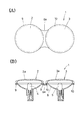
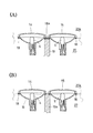
次ぎに、図面の記載に基づいて本発明の実施の形態について説明する。図面において、1は車両に組み込まれ、遠目用と近目用のランプ部があるヘッドランプやテールランプに代表される二連のランプであって、該二連ランプ1は、第一ランプ部2と第二ランプ部3とが隣接する状態で一体に形成されたものであり、そして本実施の形態では、両ランプ部2、3のレンズ部2a、3aは別体であるが、対応するバルブ(光源:電球)4、5が組み込まれるハウジング6は共通する一体物となっている。つまり、ハウジング6には、両ランプ部2、3を連結するための連結部6aが形成されている。
Next, embodiments of the present invention will be described with reference to the drawings. In the drawings, reference numeral 1 denotes a double lamp typified by a head lamp and a tail lamp incorporated in a vehicle and having a long-eye lamp and a near-eye lamp section. In the present embodiment, the
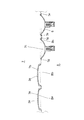
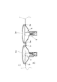
次に、前記二連ランプ1を成型するための手順について図面を用いて説明する。図2に示す工程は一次射出する第一工程を示すが、ここにおいて7は第一金型、8は第二金型であって、本実施の形態では第二金型8が第一金型7に対して離接移動とスライド移動とをする設定になっているが、該移動するための具体的構成は従来の技術を採用しているため、その詳細については省略する。
第一金型7、第二金型8には、隣接する各レンズ部2a、3aとハウジング6とを各成型するための型部7a、7b、7c、8a、8b、8cが形成されているが、さらに後述する二次射出スペースSを形成するため、第一金型7には等目凸型部7d、7eがレンズ部2a、3aの外周を囲繞するようにして形成されている。そして図2に示すように、第一、第二金型7、8が型合わせされた状態でレンズ部2a、3aそしてハウジング6を成型すべく樹脂材が各別に一次射出される。これらの樹脂材は、各別に射出されるため同材であっても異材であっても良いことはいうまでもない。
Next, a procedure for molding the dual lamp 1 will be described with reference to the drawings. The process shown in FIG. 2 shows the first process of primary injection, where 7 is the first mold, 8 is the second mold, and in this embodiment, the second mold 8 is the first mold. 7 is set to perform a separation movement and a slide movement, but since a specific configuration for the movement employs a conventional technique, the details thereof are omitted.
The
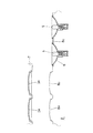
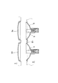
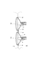
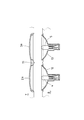
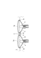
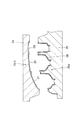
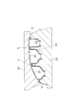
ついで図3に示す第二工程では、第二金型8が第一金型7から離間移動をして脱型され、この脱型状態で、レンズ部2a、3aは第一金型7側に型保持され、ハウジング6は第二金型8側に型保持される。この脱型状態でバルブ4、5等の必要部品が組み込まれた後、図4の第三工程で示すように第二金型8をスライド移動して前記レンズ部2a、3aとハウジング6とを互いに対向せしめた後、図5の第四工程で示すように第二金型8を第一金型7に近接移動して型合わせをする。この型合わせ状態では、レンズ部2a、3aの周縁部がハウジング6に対して断面略L字形をする状態で突合され、該各突合せ面9の外側に二次射出スペースS、Saが形成される。次に、図6の第五工程に示すように、前記二次射出スペースS、Saに樹脂材9、10が二次射出され、これによってランプ1が一連の製造工程により成型される。因みに、二次射出される樹脂材9、10は一次射出されるレンズ部2a、3aと同じ材質としても良く、またハウジング6と同じ材質としても良く、さらにはこれらと異なる材質としてもよい。
因みに、本実施の形態ではバルブ4、5は予め組み込んでおく非交換方式のもので実施されているが、後述する実施の形態のように後付けが可能な交換可能方式としても実施できることはいうまでもなく、この場合には、一次射出工程から二次射出工程のあいだでのバルブ組み込み工程は省略できる。
Next, in the second step shown in FIG. 3, the second mold 8 is moved away from the
Incidentally, in this embodiment, the
叙述の如く構成された本実施の形態において、第一、第二のランプ部2、3を有する二連のランプ1を製造するにあたり、レンズ部2a、3aを各別に一次射出することで、レンズ部2a、3aに異なった機能(例えば色)を持たせることができる二連ランプ1になりながら、その製造を、一次、二次の射出による一連の射出工程により簡単にできることになる。この結果、ダイスライドインジェクション方式により製造されるものでありながら、二連ランプ1の製造ができることになる。
In the present embodiment configured as described above, in manufacturing the dual lamp 1 having the first and
尚、本発明は、前記実施の形態に限定されないものであることは勿論であって、図7、8に示す第二の実施の形態のように、レンズ部11側を一体物とし、ハウジング側を第一、第二ハウジング12、13となるように一次射出で成型し、これら一次成型されたレンズ部11、第一、第二ハウジング12、13を二次射出された樹脂材18により一体化するように構成しても良い。
さらには図9に示す第三の実施の形態のように、レンズ部14、15、ハウジング16、17の何れも別体のものとして一次射出により成型し、その後、樹脂材18を二次射出してこれらを一体化するに際し、該樹脂材18が、レンズ部14とハウジング16との一体化、レンズ部15とハウジング17との各一体化に加えて、これら一体化されるランプ部同志の連結部(接続部)18aを構成するように設定し、これによって両ランプ部を一連状に連結した二連ランプの射出成型ができ、このようにして本発明を実施しても良い。そしてこの場合には、レンズ部14、15、ハウジング16、17を全て異材のもので形成できるという利点がある。
因みに、第三の実施の形態のものにおいては、図10に示すように連結部18aを形成する部位の金型19、19aを第一金型20に対して交換自在(第二金型は符号20aで引きだした)とし、一方の金型19を使用した状態(A)で二次射出した場合には連結部18aがある二連ランプが成型され、他方の金型19aを使用した状態(B)で二次射出した場合には二個のランプ部が各別に成型されるように設定し、このようにすることで、必要に応じて二連ランプと一対の単一ランプとが任意に製造できるという利点がある。
Needless to say, the present invention is not limited to the above-described embodiment. As in the second embodiment shown in FIGS. The first and
Further, as in the third embodiment shown in FIG. 9, the
Incidentally, in the third embodiment, as shown in FIG. 10, the
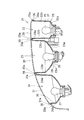
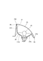
さらにまた、本発明は、図11〜18に示す第四の実施の形態としても実施することができる。このものは車両の後部に組み込まれるリヤコンビネーションランプ21であって、該リアコンビネーションランプ21は、一連状に隣接する状態で、ストップランプ部22、ウインカーランプ部23、バックランプ部24を構成する各光源(何れも後付けのバルブ)25、26、27が組込まれたランプハウジング28と、これら光源25、26、27に各対応するレンズ部29、30、31とを備えて構成されるが、これらランプハウジング28とレンズ体29、30、31とは次のようにして一体形成されている。
Furthermore, the present invention can also be implemented as a fourth embodiment shown in FIGS. This is a
つまり、前記ランプハウジング28を構成する各ランプ部22、23、24は、略椀形状に形成され、その椀底部22a、23a、24aに光源25、26、27が組み込まれ、各椀周壁22b、23b、24bのうち隣接する周壁間同志22bと23b、23bと24bは、壁先端部が連結部28a、28bによつて一連状に連結された一体物となっている。尚、椀周壁同志22bと23b、23bと24bとが対向隣接する部位については、本実施の形態のように二枚状に分割した構造にすることなく、一体化した一枚状の椀周壁として構成することも勿論できる。
That is, each
一方、レンズ部29、30、31は後述するように各別に成型されたものであって、周縁がランプハウジング28側に少し突出してリブ部29a、30a、31aになった略平板形状をし、このリブ部29a、30a、31aがランプハウジング28の椀周壁22b、23b、24bの先端縁部28aに後述するように二次射出される樹脂材36により固着(接着)される構成になっている。
On the other hand, the
さて次に、前記リアコンビネーションランプ21の製造工程を図14〜図18を用いて説明する。このリヤコンビネーションランプ21は、所謂ダイスライドインジェクション方式による一連の射出により成型されるが、図面において、34は第一金型、35は第二金型であって、本実施の形態では、第一金型34は固定型、第二金型35は第一金型34に対して離接移動が可能で、かつ型面方向に対してスライド移動が可能な設定になっている。因みに、両金型34、35の移動は相対的なものであれば足り、従って本発明を実施できるものであれば型移動の構成については格別問わないものである。そしてこれら金型34、35には、ハウジング成型部34a、35aとレンズ部成型部34b、35bとがそれぞれ形成されており、次にこれらの構成について説明する。
Next, the manufacturing process of the
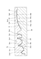
まず第一金型34であるが、このハウジング成型部34aには、ハウジング28の椀内面を形成するための三連のハウジング用凸型部34cが形成されると共に、後述するように各別に成型されるレンズ部29、30、31が突き当たる外周縁部には、後述の二次射出スペースSをハウジング28の突き当たり面部に形成するためのスペース用凸型部34dが形成されている。一方、レンズ成型部34bには、各レンズ部29、30、31の外面を形成するためのレンズ用型部34eが形成されている。
First, the
これに対し、第二金型35であるが、このハウジング成型部35aにはハウジング28の外面を成型するためのハウジング用型部35cが形成される一方、レンズ成型部35bには、各レンズ内面を成型するためのレンズ用型部35dが形成されるが、さらに隣接するレンズ部同志29と30、30と31のあいだには、後述する二次射出スペースSを形成するためのスペース用型部35eと、前述したフランジ部28cに突き当たるレンズ部29の突き当たり面に二次射出用スペースSを形成するためのスペース用型部35fが形成されている。そしてこれらスペース用型部34d、35e、35fによつて形成される二次射出スペースSはコーナー部において連通するように型設定されている。
On the other hand, the
次にこのような型設定された第一、第二金型34、35を用いてリヤコンビネーションランプ21を射出成型する手順について説明する。まず、図14で示される第一工程では、両金型34、35のハウジング成型部同志34a、35a、レンズ成型部同志34b、35bが対向する状態で型合わせされ、ハウジングスペースに不透光の樹脂材が一次射出されてハウジング28が成型される一方、各レンズ部スペースには、透光で、かつ無色あるいは赤や黄色に着色された樹脂材が対応するレンズ部スペースにそれぞれ一次射出されてレンズ部29、30、31が成型される。
Next, a procedure for injection molding the
ついで図14に示す第二工程では、第二金型35が第一金型34から離間する方向に移動して脱型され、この場合に、ハウジング28は第二金型35側に、レンズ部29、30、31は第一金型34側に付着する設定になっている。尚、本実施の形態では、この脱型状態で、ハウジング成型部15aの各椀部に対応する反射板37、38、39が後付けされる状態で組み込まれる。
Next, in the second step shown in FIG. 14, the
ついで、図16の第三工程に示す如く、ハウジング成型部35aが第一金型34のレンズ成型部34bに対応する位置まで第二金型35がスライド移動した後、図17の第四工程に示す如く、該ハウジング成型部35aとレンズ成型部34bとが型合わせされるよう第二金型35が第一金型34側に移動する。この型合わせ状態で、前述した二次射出スペースSが形成され、該射出スペースSに、例えばハウジング28を成型した樹脂材36を二次射出し(図18)、これによってハウジング28に各レンズ部29、30、31、が一体に固着されたコンビネーションランプの外殻が形成され、これに電球25、26、27を後付けする等して組み込むことでコンビネーションランプ21が形成され、このようにすることで、レンズ部面積が大きいコンビネーションランプ21を簡単に型成型することができる。
Next, as shown in the third step of FIG. 16, after the
1 照明装置
2 第一ランプ部
2a レンズ部
3 第二ランプ部
3a レンズ部
9、10 二次射出される樹脂材
21 リヤコンビネーションランプ
DESCRIPTION OF SYMBOLS 1
Claims (6)
6. The lighting device according to claim 5, wherein the lighting device is a combination lamp having at least three lamp chambers, wherein the combination lamp includes a housing in which each of the lamp chambers is partitioned by a partition wall, and a lens corresponding to each of the lamp chambers. An injection molded body or a method for manufacturing the same, wherein the lens portion is integrated with the leading edge of the partition wall by secondary injection.
Priority Applications (1)
| Application Number | Priority Date | Filing Date | Title |
|---|---|---|---|
| JP2007246995A JP4533921B2 (en) | 2007-09-25 | 2007-09-25 | Manufacturing method of injection molded body |
Applications Claiming Priority (1)
| Application Number | Priority Date | Filing Date | Title |
|---|---|---|---|
| JP2007246995A JP4533921B2 (en) | 2007-09-25 | 2007-09-25 | Manufacturing method of injection molded body |
Related Parent Applications (1)
| Application Number | Title | Priority Date | Filing Date |
|---|---|---|---|
| JP2001329704A Division JP2003127175A (en) | 2001-10-26 | 2001-10-26 | Injection molded body and method of manufacturing the same |
Publications (2)
| Publication Number | Publication Date |
|---|---|
| JP2008024005A true JP2008024005A (en) | 2008-02-07 |
| JP4533921B2 JP4533921B2 (en) | 2010-09-01 |
Family
ID=39115105
Family Applications (1)
| Application Number | Title | Priority Date | Filing Date |
|---|---|---|---|
| JP2007246995A Expired - Fee Related JP4533921B2 (en) | 2007-09-25 | 2007-09-25 | Manufacturing method of injection molded body |
Country Status (1)
| Country | Link |
|---|---|
| JP (1) | JP4533921B2 (en) |
Cited By (1)
| Publication number | Priority date | Publication date | Assignee | Title |
|---|---|---|---|---|
| JP2010111045A (en) * | 2008-11-07 | 2010-05-20 | Oshima Denki Seisakusho:Kk | Method of manufacturing injection-molded article |
Citations (5)
| Publication number | Priority date | Publication date | Assignee | Title |
|---|---|---|---|---|
| JPH0531003U (en) * | 1991-09-25 | 1993-04-23 | 株式会社小糸製作所 | Vehicle lighting |
| JPH0575911U (en) * | 1992-03-17 | 1993-10-15 | 株式会社小糸製作所 | Vehicle lighting |
| JPH0976288A (en) * | 1995-09-08 | 1997-03-25 | Japan Steel Works Ltd:The | Injection molding method and injection molding die |
| JPH09216260A (en) * | 1996-02-08 | 1997-08-19 | Japan Steel Works Ltd:The | Injection mold |
| JPH11162210A (en) * | 1997-11-28 | 1999-06-18 | Inoac Corporation:Kk | Lamp for vehicle and manufacture thereof |
-
2007
- 2007-09-25 JP JP2007246995A patent/JP4533921B2/en not_active Expired - Fee Related
Patent Citations (5)
| Publication number | Priority date | Publication date | Assignee | Title |
|---|---|---|---|---|
| JPH0531003U (en) * | 1991-09-25 | 1993-04-23 | 株式会社小糸製作所 | Vehicle lighting |
| JPH0575911U (en) * | 1992-03-17 | 1993-10-15 | 株式会社小糸製作所 | Vehicle lighting |
| JPH0976288A (en) * | 1995-09-08 | 1997-03-25 | Japan Steel Works Ltd:The | Injection molding method and injection molding die |
| JPH09216260A (en) * | 1996-02-08 | 1997-08-19 | Japan Steel Works Ltd:The | Injection mold |
| JPH11162210A (en) * | 1997-11-28 | 1999-06-18 | Inoac Corporation:Kk | Lamp for vehicle and manufacture thereof |
Cited By (1)
| Publication number | Priority date | Publication date | Assignee | Title |
|---|---|---|---|---|
| JP2010111045A (en) * | 2008-11-07 | 2010-05-20 | Oshima Denki Seisakusho:Kk | Method of manufacturing injection-molded article |
Also Published As
| Publication number | Publication date |
|---|---|
| JP4533921B2 (en) | 2010-09-01 |
Similar Documents
| Publication | Publication Date | Title |
|---|---|---|
| CN105538599A (en) | Two-color molding method, two-color molding mold, and two-color molded article | |
| US7722196B2 (en) | Plastic injection of lenses with optical elements and/or retroreflecting prisms that are separated from each other | |
| JP2002313107A (en) | VEHICLE LIGHTING APPARATUS AND INJECTION MOLDING DIE FOR LAMP BODY AND METHOD OF MANUFACTURING | |
| JP2012190761A (en) | Vehicular lamp | |
| KR101204537B1 (en) | Deposition molded product, deposition molding method, and deposition molding apparatus | |
| JP4707153B2 (en) | Molded body, molded body manufacturing method, and molded body manufacturing apparatus | |
| JP2003127175A (en) | Injection molded body and method of manufacturing the same | |
| JP4533921B2 (en) | Manufacturing method of injection molded body | |
| JP2008168577A (en) | Injection molded body, method for manufacturing injection molded body, and mold for manufacturing injection molded body | |
| US20020167816A1 (en) | Lens in vehicular lamp, method of shaping the lens and an apparatus for shaping the lens | |
| JP2008018734A (en) | Method for producing lamp | |
| JP4658651B2 (en) | Injection molded body, injection molding body manufacturing method and manufacturing apparatus | |
| JP4541386B2 (en) | Injection molding body manufacturing equipment | |
| US11027642B2 (en) | Bezel apparatus for use with vehicle lamps and related methods | |
| JP4606900B2 (en) | Method for producing film-formed molded body | |
| CN109414856A (en) | The manufacturing method of mold and dual-color forming product | |
| JP2008265006A (en) | Injection molded body, injection mold, and injection molding method thereof | |
| KR101373673B1 (en) | Rear lamp for vehicles and making method thereof | |
| US20080018006A1 (en) | Method of injection molding lens of transparent or semitransparent plastic material for producing car lights and similar | |
| JP2003109412A (en) | Vehicle lighting device and method of manufacturing the same | |
| JP7505246B2 (en) | Resin parts for vehicles, vehicle lighting fixtures | |
| JP2010153113A (en) | Method for manufacturing lamp for vehicle, lens of vehicle lamp, and sheet member for lens forming of vehicle lamp | |
| JP6584265B2 (en) | Light guide, method for molding light guide, and mold apparatus | |
| JP4014141B2 (en) | Injection molding body manufacturing equipment | |
| JPWO2003020490A1 (en) | Injection molded body and method for producing the same |
Legal Events
| Date | Code | Title | Description |
|---|---|---|---|
| A131 | Notification of reasons for refusal |
Free format text: JAPANESE INTERMEDIATE CODE: A131 Effective date: 20100318 |
|
| A711 | Notification of change in applicant |
Free format text: JAPANESE INTERMEDIATE CODE: A711 Effective date: 20100324 |
|
| RD02 | Notification of acceptance of power of attorney |
Free format text: JAPANESE INTERMEDIATE CODE: A7422 Effective date: 20100402 |
|
| A521 | Written amendment |
Free format text: JAPANESE INTERMEDIATE CODE: A523 Effective date: 20100512 |
|
| TRDD | Decision of grant or rejection written | ||
| A01 | Written decision to grant a patent or to grant a registration (utility model) |
Free format text: JAPANESE INTERMEDIATE CODE: A01 Effective date: 20100603 |
|
| A01 | Written decision to grant a patent or to grant a registration (utility model) |
Free format text: JAPANESE INTERMEDIATE CODE: A01 |
|
| A61 | First payment of annual fees (during grant procedure) |
Free format text: JAPANESE INTERMEDIATE CODE: A61 Effective date: 20100614 |
|
| R150 | Certificate of patent or registration of utility model |
Free format text: JAPANESE INTERMEDIATE CODE: R150 |
|
| FPAY | Renewal fee payment (event date is renewal date of database) |
Free format text: PAYMENT UNTIL: 20130618 Year of fee payment: 3 |
|
| LAPS | Cancellation because of no payment of annual fees |