JP2008024409A - Pit ladder device for elevator - Google Patents
Pit ladder device for elevator Download PDFInfo
- Publication number
- JP2008024409A JP2008024409A JP2006197869A JP2006197869A JP2008024409A JP 2008024409 A JP2008024409 A JP 2008024409A JP 2006197869 A JP2006197869 A JP 2006197869A JP 2006197869 A JP2006197869 A JP 2006197869A JP 2008024409 A JP2008024409 A JP 2008024409A
- Authority
- JP
- Japan
- Prior art keywords
- pit
- vertical bar
- ladder
- elevator
- hoistway
- Prior art date
- Legal status (The legal status is an assumption and is not a legal conclusion. Google has not performed a legal analysis and makes no representation as to the accuracy of the status listed.)
- Pending
Links
- 230000007246 mechanism Effects 0.000 claims description 18
- 238000012790 confirmation Methods 0.000 claims description 13
- 230000000087 stabilizing effect Effects 0.000 abstract 1
- 102000001999 Transcription Factor Pit-1 Human genes 0.000 description 7
- 108010040742 Transcription Factor Pit-1 Proteins 0.000 description 7
- 238000010586 diagram Methods 0.000 description 5
- 238000009434 installation Methods 0.000 description 2
- 238000000034 method Methods 0.000 description 2
- 125000002066 L-histidyl group Chemical group [H]N1C([H])=NC(C([H])([H])[C@](C(=O)[*])([H])N([H])[H])=C1[H] 0.000 description 1
- 238000007689 inspection Methods 0.000 description 1
- 238000012423 maintenance Methods 0.000 description 1
Images

Landscapes
- Lift-Guide Devices, And Elevator Ropes And Cables (AREA)
- Maintenance And Inspection Apparatuses For Elevators (AREA)
Abstract
Description
本発明は、エレベータの昇降路のピット内に設けられ、ピット床面とピットに隣接するかごに対する出入口とを連絡するためのエレベータのピットはしご装置に関する。 The present invention relates to an elevator pit ladder apparatus that is provided in a pit of an elevator hoistway and communicates a pit floor surface with an entrance to a car adjacent to the pit.
一般に、エレベータにおいて、点検や補修等のメンテナンス作業を行うために、作業員が、昇降路の最下部に設けられているピットのピット床面に最下階のエレベータホールの乗場ドアを開放した状態の出入口から下りることがあるので、ピット内に予めはしご(ピットはしご装置)が準備されている。 In general, in an elevator, in order to perform maintenance work such as inspection and repair, a worker opens the landing door of the elevator hall on the lowest floor on the pit floor of the pit provided at the bottom of the hoistway Since there is a possibility of descending from the entrance / exit, a ladder (pit ladder device) is prepared in advance in the pit.
エレベータの通常運転時には、エレベータの昇降路の最下部に設けられたピット内にエレベータのかごが降りてくることはないが、高い安全性を確保するために、ピット内にかごが入るスペースを確保しておく必要がある。したがって、ピット内におけるはしごの設置位置、又は収納位置を工夫する必要がある。 During normal operation of the elevator, the elevator car does not descend into the pit provided at the bottom of the elevator hoistway, but to ensure high safety, a space for the car to enter the pit is secured. It is necessary to keep it. Therefore, it is necessary to devise the installation position or the storage position of the ladder in the pit.
図8は特許文献1に記載されたピット内におけるはしごの設置方法を示す上面図である。エレベータの昇降路1の最下部に設けられたピット2においては、かご3と釣合重り4のスペースが確保されている。最下階のエレベータホールに通じるかご3への出入口5が形成されている昇降路1の一つの壁6における出入口5の下側位置に乗場シル7が昇降路1内へ突設されている。この乗場シル7は利用客が出入口5からかご3へ安全に乗り移るために設けられている。はしご8は、この乗場シル7の下面とピット2のピット床面9との間に、設けられている。
FIG. 8 is a top view showing a ladder installation method in the pit described in
具体的には、はしご8を構成する一対の縦棒10a、10bの一方の縦棒10aを乗場シル7の下面とのピット床面9との間に上下方向に余裕を持って回転自在に支持し、このはしご8の不使用状態(通常状態)時には、このはしご8を壁6に平行状態に回動して、他方の縦棒10bの下端を壁6近傍のピット床面9に穿設された第1の固定穴に嵌め込まれている。すなわち、この不使用状態(通常状態)時においては、はしご8は乗場シル7の下側に収納されている。
Specifically, one
そして、作業員がピット2内で、作業を行う場合においては、はしご8を少し持ち上げて、他方の縦棒10bの下端を固定穴から外して、図8に示すように、はしご8を一方の縦棒10aを中心に時計方向に90度回動させ、他方の縦棒10bの下端を当該位置に穿設された第2の固定穴に嵌め込み固定する。この状態で、作業員はこのはしご8を利用して、出入口5からピット床面9へ降りる。ピット2内における一連の作業が終了すると、はしご8を元の壁6に対する平行状態に戻し、他方の縦棒10bの下端を元の第1の固定穴に嵌め込み固定する。
しかしながら上述した収納手法を採用した、エレベータのピットはしご装置においてもまだ改良すべき次のような課題があった。 However, the elevator pit ladder apparatus employing the above-described storage method still has the following problems that should be improved.
すなわち、作業員は、ピット2内での作業を実行するに先だって、出入口5から自己の下方に位置するはしご8を、少し持ち上げて、壁6に対して、直交する方向まで回動させて、他方の縦棒10bの下端を当該位置に穿設された第2の固定穴に嵌め込み固定する必要がある。しかしながら、この下方に位置するはしご8に対する作業は、作業員にとって不安定な姿勢での作業となり、安全性の問題が生じる。さらに、煩雑な長時間を有する作業となる。
That is, prior to performing the work in the
また、はしご8の使用時における回動角が90度に固定されており、ピット2内のピット床面9に第2の固定穴が予め穿設されている。しかし、ピット2内のピット床面9には、かごダンパを含む複数の機器が設置されているので、はしご8を任意の回動角度状態で使用できることが要求されている。
Further, the rotation angle when the
本発明はこのような事情に鑑みてなされたものであり、ピット内で作業を行う作業員にとって、簡単にかつ安全に、ピット内の収納位置から使用可能位置への引出し、作業員自体の昇降路の壁に形成されたかごへの出入口からピット床面への移動、及びピット床面から出入口への移動、使用後におけるピット内における収納を図ることができるエレベータのピットはしご装置を提供することを目的とする。 The present invention has been made in view of such circumstances. For an operator who works in a pit, the operator can easily and safely pull out from the storage position in the pit to the usable position, and raise and lower the worker itself. To provide an elevator pit ladder apparatus that can be moved from the entrance to the pit floor to the pit floor formed on the road wall, moved from the pit floor to the entrance, and stored in the pit after use. With the goal.
上記課題を解消するために、本発明は、エレベータの昇降路のピット内に設けられ、ピット床面と当該ピットに隣接するかごへの出入口とを連絡する、第1、第2の縦棒とこの第1、第2の縦棒を連結する複数のステップとを有するエレベータのピットはしご装置において、第1の縦棒の上端部及び下端部に設けられ、当該縦棒の上端及び下端を、出入口の下側端の昇降路内に突設された乗場シルの下面とピット床面とに対して回動自在にかつ上下移動自在に支持する一対の支持機構と、この一対の支持機構に組込まれ第1の縦棒及びこの第1の縦棒にステップを介して接続された第2の縦棒を上方へ付勢するばね部材と、第2の縦棒の下端に固定され、通常状態時においてはばね部材の上方への付勢力にてピット床面と離間しており、第1の軸棒が回動された状態において、ステップに対する下方への荷重印加に応じてばね部材の上方への付勢力に抗してピット床面に当接するストッパー部材とを備えている。 In order to solve the above-mentioned problems, the present invention is provided in first and second vertical bars provided in a pit of an elevator hoistway, which communicates a pit floor and an entrance to a car adjacent to the pit. In an elevator pit ladder apparatus having a plurality of steps for connecting the first and second vertical bars, the upper and lower ends of the first vertical bar are provided at the upper and lower ends of the first vertical bar. A pair of support mechanisms that support the lower surface of the landing sill projecting in the hoistway at the lower end and the pit floor surface so as to be rotatable and vertically movable, and are incorporated into the pair of support mechanisms. A first vertical bar and a spring member that urges the first vertical bar connected to the first vertical bar through a step upward, and is fixed to the lower end of the second vertical bar, and in a normal state Is separated from the pit floor by the upward biasing force of the spring member, In a state in which the shaft rod is rotated, and a stopper member in contact with the pit floor surface against the urging force of the upward spring member in accordance with the load applied downward to a step.
このように構成されたエレベータのピットはしご装置においては、このピットはしご装置(以下、単に「はしご」と略記する)の第1の縦棒の上下端は、乗場シルの下面とピット床面に回動自在でかつ上下移動自在に支持されている。そして、例えば、作業員がステップに足をかけていない状態、すなわち、このはしごが使用されていない通常状態において、このはしごの昇降路の壁に対する回動角度が「0」に設定されている。したがって、この状態においては、はしごはピット内の乗場シルの下方位置に収納されている。 In an elevator pit ladder apparatus configured as described above, the upper and lower ends of the first vertical bar of the pit ladder apparatus (hereinafter simply referred to as “ladder”) are routed to the lower surface of the landing sill and the pit floor surface. It is supported so that it can move and move up and down. For example, in a state where the worker does not step on the step, that is, in a normal state where the ladder is not used, the rotation angle of the ladder with respect to the hoistway wall is set to “0”. Therefore, in this state, the ladder is stored at a position below the landing sill in the pit.
このはしごの第1、第2の縦棒はばね部材で上方へ付勢されているので、第2の縦棒の下端のストッパー部材はピット床に接触しなく、作業員は簡単に、はしごを昇降路の壁に対して任意の回動角に移動させることが可能である。はしごが目的の角度に位置した状態で、作業員がステップに足を掛けると、下方に荷重が印加され、第2の縦棒の下端のストッパー部材がピット床面に当接する。したがって、作業員はしごを任意角度に設定して使用可能である。 Since the first and second vertical bars of this ladder are biased upward by a spring member, the stopper member at the lower end of the second vertical bar does not come into contact with the pit floor, and the operator can easily lift the ladder. It can be moved to any rotation angle with respect to the wall of the hoistway. When the operator steps on the step with the ladder positioned at the target angle, a load is applied downward, and the stopper member at the lower end of the second vertical bar comes into contact with the pit floor. Therefore, the worker can use the ladder set at an arbitrary angle.
また、別の発明は、上述した発明のエレベータのピットはしご装置において、第2の縦棒内に形成された上端に連通する収納部に対して、第2の縦棒の上方へ引出し自在に収納された棒状手すりを備えている。 According to another invention, in the elevator pit ladder apparatus according to the above-described invention, the storage unit communicating with the upper end formed in the second vertical bar is retractably stored above the second vertical bar. It has a bar-shaped handrail.
このように構成されたエレベータのピットはしご装置においては、壁に形成された出入口にいる作業員は、この棒状手すりを第2の縦棒の上端から引出して使用することにより、より安全にはしごの乗り降り、及びはしごの引出し、収納操作を実施できる。 In the elevator pit ladder apparatus constructed as described above, the worker at the doorway formed on the wall can use the bar-shaped handrail by pulling it out from the upper end of the second vertical bar. You can get on and off, and pull out and store the ladder.
また、別の発明は、上述した発明のエレベータのピットはしご装置において、通常状態時においては、第1、第2の縦棒を含む面が昇降路における出入口が形成された壁に平行になるように、第1の縦棒に回動力を付与するクローザ機構を備えている。 Further, according to another invention, in the elevator pit ladder apparatus according to the above-described invention, in a normal state, the plane including the first and second vertical bars is parallel to the wall in which the entrance / exit in the hoistway is formed. In addition, a closer mechanism for applying a turning force to the first vertical bar is provided.
このように構成されたエレベータのピットはしご装置においては、作業員がはしごから離れると、はしごは、自動的に第1、第2の縦棒を含む面が昇降路における出入口が形成された壁に平行になるように、自動的に戻る。 In the elevator pit ladder apparatus configured as described above, when the worker leaves the ladder, the ladder automatically has the surface including the first and second vertical bars on the wall where the entrance / exit in the hoistway is formed. Automatically return to be parallel.
また、別の発明は、上述した発明のエレベータのピットはしご装置において、第1の縦棒の回動角が、第1、第2の縦棒を含む面が昇降路における出入口が形成された壁に平行になる基準回動角に一致しないと、エレベータに対する安全確認信号を出力しない安全回路を備えている。 According to another aspect of the present invention, in the elevator pit ladder apparatus according to the present invention, the first vertical bar has a rotation angle, and the wall including the first and second vertical bars is formed with an entrance / exit in the hoistway. A safety circuit is provided that does not output a safety confirmation signal for the elevator unless the reference rotation angle is parallel to the elevator.
このように構成されたエレベータのピットはしご装置においては、はしごが乗場シルの下側に収納されていない状態においては、エレベータに対する安全確認信号が出力されないので、作業の安全性を向上することができる。 In the elevator pit ladder apparatus configured as described above, in the state where the ladder is not housed under the landing sill, a safety confirmation signal for the elevator is not output, so that the safety of work can be improved. .
本発明においては、簡単にかつ安全に、はしごをピット内の収納位置から使用可能位置への引出し、使用後におけるピット内における収納を実施でき、ピット内で作業を行う作業員に対する良好な作業環境を提供できる。 In the present invention, it is possible to easily and safely draw the ladder from the storage position in the pit to the usable position, and to store the ladder in the pit after use, and a good working environment for workers who work in the pit. Can provide.
以下、本発明の一実施形態を図面を用いて説明する。 Hereinafter, an embodiment of the present invention will be described with reference to the drawings.
図1は本発明の一実施形態に係わるエレベータのピットはしご装置が組込まれたエレベータシステム全体を示す模式図である。 FIG. 1 is a schematic view showing an entire elevator system in which an elevator pit ladder apparatus according to an embodiment of the present invention is incorporated.
建屋内に設けられた昇降路11の下部にピット12が設けられ、昇降路11の上側に機械室13が配置されている。昇降路11の各階のエレベータホールに対向する壁14にかご18に対する乗り降りするための出入口15が形成されている。この出入口15には図示しない乗場ドアが取付けられている。各出入口15の下側位置に乗場シル16が昇降路11内へ突設されている。この乗場シル16は利用客が出入口15からかご18へ安全に乗り移るために設けられている。機械室13内には、巻上機17が設置されており、この巻上機17のシーブ17aに、両端にかご18及び釣合重り19が接続された主ロープ20が懸架されている。制御盤21は巻上機17を駆動して、がご18を利用者が指定した階へ移動制御する。
A
昇降路11のピット12内の乗場シル16の下面とピット床面22の間に、実施形態のエレベータのピットはしご装置としてのはしご23が収納されている。
Between the lower surface of the landing
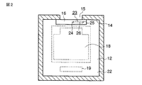
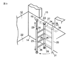
図2は昇降路11のA−A’線で切断したピット12の水平断面図であり、図3はピット12を斜め上方から見た斜視図である。図2に示すように、このピット12においてはかご18と釣合重り19の収納領域が確保されている。図3に示すように、はしご23は互いに平行する第1の縦棒24と第2の縦棒25と両者を接続する4本のステップ26とで構成されている。第1の縦棒24の上端部及び下端部には、当該縦棒24の上端及び下端を、乗場シル16の下面とピット床面22とに対して回動自在にかつ上下移動自在に支持する一対の支持機構27、28が組込まれている。
FIG. 2 is a horizontal sectional view of the
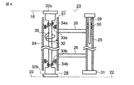
一方、第2の縦棒25内には、図4に示すように、棒状手すり29が第2の縦棒25の上方へ引出し自在に収納されている。この棒状手すり29には第2の縦棒25の上方へ引出たときにずり落ちないように、緩衝材30で第2の縦棒25内に支持されている。第2の縦棒25の下端にはストッパー部材31が取付けられている。
On the other hand, as shown in FIG. 4, a rod-
図2は、はしご23を乗場シル16の下側に収納した状態を示し、図3は、はしご23を第1の縦棒24を中心に時計方向に90度回動してピット12の中央部に引出した状態を示す。なお、はしご23を乗場シル16の下側に収納した状態においては、棒状手すり29は上方へ引出せなく、はしご23をピット12の中央部に引出した状態において、棒状手すり29を乗場シル16より上方に引出ことが可能である。
FIG. 2 shows a state in which the
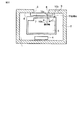
図4は、第1の縦棒24の上端及び下端を、乗場シル16の下面とピット床面22とに対して回動自在にかつ上下移動自在に支持する各支持機構27、28の詳細構成を示すはしご23の断面模式図である。
FIG. 4 shows the detailed configuration of the
第1の縦棒24内に形成された貫通孔に固定軸32が挿入されており、この固定軸32の上端32aが乗場シル16の下面に固定され、固定軸32の下端32bがピット床面22に固定される。第1の縦棒24内に形成された貫通孔の上部位置及び下部位置には、水平面内に回転可能な環状板33a、33bが設けられ、この環状板33a、33bと固定軸32に形成された段部との間にコイルばね34a、34bが介挿されている。
A fixed
このように構成された支持機構27、28において、第1の縦棒24は上下端32a、32bが乗場シル16の下面及びピット床面22に固定された固定軸32に対して回動可能である。さらに、第1の縦棒24はコイルばね34a、34bにて、上方へ付勢されている。第1の縦棒24にはステップ26を介して第2の縦棒25が接続されているので、この状態においては、この第2の縦棒25の下端のストッパー部材31は、ピット床面22と離間している。
In the
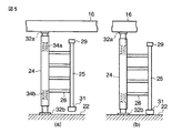
したがって、このはしご23を使用していない、図5(a)に示す状態において、作業員がこのはしご23を使用するために、ステップ26に足を掛けると、ステップ26に対して下向きの荷重が印加され、第1の縦棒24、第2の縦棒25が、コイルばね34a、34bの上方への付勢力に抗して下方へ移動し、ストッパー部材31がピット床面22に当接する。
Therefore, in the state shown in FIG. 5A in which the
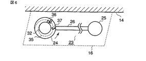
さらに、図4に示すように、第1の縦棒24内に形成された貫通孔と固定軸32との間にはコイルばねバネ35がクローザ機構として組込まれている。このクローザ機構及び安全回路について図6を用いて説明する。図6に示すように、第1の縦棒24内に形成された貫通孔と固定軸32との間には、前述したコイルばねバネ35の他に、固定軸32に対する第1の縦棒24の回動動作を停止する回動ストッパー36、及び接点37が組込まれている。
Furthermore, as shown in FIG. 4, a
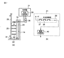
すなわち、このはしご23を使用していない、図5(a)に示す状態においては、第1の縦棒24は、固定軸32に対して、矢印で示す反時計方向の回転力が付勢されており、はしご23は回動ストッパー36にて、ピット12の壁14に平行状態の基準回動角で強制停止されている。接点37は、はしご23がピット12の壁14に平行状態、すなわち、はしご23が乗場シル16の下側に収納されている状態にのみオン状態となる。この接点37のオン/オフ状態は、図7(a)に示すように、機器室13の制御盤21内に組込まれた安全制御部39にて監視されている。
That is, in the state shown in FIG. 5A in which the
さらに、ピット12に対する出入口15近傍の昇降路11内の壁14には、ピット安全スイッチ38が取付けられている。作業員は、ピット12で作業を開始するに前に、ピット安全スイッチ38を開放し、ピット12での作業が終了して、ピット12から出入口15へ退出するときにピット安全スイッチ38を投入する。
Further, a
図7(b)は機器室13の制御盤21内に組込まれた安全制御部39の回路構成図である。+vボルトの安全確認信号がクローザ機構に設けられた接点37、ピット安全スイッチ38、その他の複数の接点を直列に介して巻上機17を駆動制御する駆動制御部40に入力される。
FIG. 7B is a circuit configuration diagram of the
このような構成においては、はしご23が壁14に対する平行状態から第1の縦棒24を中心に時計回りに回動して、接点37が開放されると、安全確認信号が駆動制御部40へ入力されない。ピット安全スイッチ38も投入されていないと安全確認信号は駆動制御部40に入力されない。駆動制御部40は安全確認信号が入力されている状態において、巻上機17の駆動が可能となる。すなわち、接点37は、はしご23が平行状態でない基準回動角以外はエレベータに対する安全確認信号を出力しない安全回路を構成する。
In such a configuration, when the
このように構成されたエレベータのピットはしご装置の使用例を図3を用いて説明する。作業員がピット12内での作業をしていない状態においては、はしご23は点線で示すように乗場シル16の下側に収納されている。したがって、クローサ機構に設けられた接点37、ピット安全スイッチ38は閉じられているため、機械室13の制御盤21の安全制御部部39は安全確認信号を駆動制御部40へ送出しているため、エレベータは正常に運転可能である。
An example of use of the elevator pit ladder apparatus configured as described above will be described with reference to FIG. When the worker is not working in the
作業員がピット12内での作業を開始する場合、エレベータをマニュアル運転で2階以上の階に停止させて、1階の出入口15の扉を開けて、昇降路11内の壁14に設けられたピット安全スイッチ38を開放して、駆動制御部40への安全確認信号を遮断する。次に、はしご23の第2の縦棒25を持って、このはしご23を時計方向に少し回動させて、第2の縦棒25の上端が乗場シル16の外側に出ると、棒状手すり29を上方へ引出す。
When the worker starts work in the
作業員が、この棒状手すり29をもって、はしご23を作業に適した角度に設定したのち、はしご23のステップ26に乗り移ると、作業員の自重にて、第1、第2の縦棒24、25、各ステップ26が下方へ移動して、第2の縦棒25の下端のストッパー部材31がピット床面22に当接して、はしご23は安定する。したがって、作業員は安全にピット床面22に降り立つことができる。
After the worker sets the
ピット床面22において、作業員がはしご23から離れると、はしご23の第1、第2の縦棒24、25がコイルばね34a、34bにて上方へ移動し、クローザ機構にて、はしご23が基準回動角度位置である元の収納位置に戻ろうとする。しかし、上方へ引出された棒状手すり29が乗場シル16の前面に当接するので、はしご23は完全に元の収納位置に戻ることはない。したがって、駆動制御部40への安全確認信号は遮断されたままである。したがって、ピット12内で各種の作業を行っている作業者の安全性が確保される。この場合、はしご23は自動的に元の収納位置近傍に戻るので、作業の邪魔になることはない。
When the worker leaves the
作業員は、ピット12内での作業が終了すると、はしご23を自己が利用し易い角度まで引出して、このはしご23を用いて、出入口15まで昇る。そして、棒状手すり29を第2の縦棒25の上端における元の位置まで差込むと、クローサ機構にて、はしご23が基準回動角度位置である元の収納位置に自動的に戻る。したがって接点37は閉成される。最後に、作業員は昇降路11内の壁14に設けられたピット安全スイッチ38を投入する。その結果、機械室13の制御盤21の安全制御部部39は安全確認信号を駆動制御部40へ送出開始し、エレベータは運転可能状態に移行する。
When the worker finishes the work in the
以上説明したように、このはしご23が使用されていない通常状態において、このはしご23はピット12内の乗場シル16の下方位置に収納されている。また、はしご23の第1、第2の縦棒24、25は上方へ付勢されているので、第2の縦棒25の下端のストッパー部材31はピット床面22に接触しなく、作業員は簡単に、はしご23を昇降路11の壁14に対して任意の回動角に移動させることが可能である。また、クローザ機構にて、はしご23を使用していない時には、自動的に元の収納位置に戻るようにしている。したがって、作業員の負担を軽減できる。
As described above, in a normal state in which the
また、はしご23の第2の縦棒25には、上方へ引出し可能な棒状手すり29が設けられているので、作業員はより安全にはしご23の乗り降り、及びはしご23の引出しを実施できる。
Further, since the second
さらに、はしご23が乗場シル16の下側に収納されていない状態においては、駆動制御部40に安全確認信号が入力されないので、ピット12における作業期間中にエレベータが誤って動くことがより確実に防止される。
Furthermore, in a state where the
11…昇降路、12…ピット、13…機械室、14…壁、15…出入口、16…乗場シル、18…かご、22…ピット床面、23…はしご、24…第1の縦棒、25…第2の縦棒、26…ステップ、27,28…支持機構、29…棒状手すり、31…ストッパー部材、32…固定軸、34a,34b,35…コイルばね、37…接点、38…安全スイッチ、40…駆動制御部 11 ... hoistway, 12 ... pit, 13 ... machine room, 14 ... wall, 15 ... doorway, 16 ... landing sill, 18 ... car, 22 ... pit floor, 23 ... ladder, 24 ... first vertical bar, 25 ... second vertical bar, 26 ... step, 27,28 ... support mechanism, 29 ... bar-shaped handrail, 31 ... stopper member, 32 ... fixed shaft, 34a, 34b, 35 ... coil spring, 37 ... contact, 38 ... safety switch , 40 ... Drive control unit
Claims (5)
前記第1の縦棒の上端部及び下端部に設けられ、当該縦棒の上端及び下端を、前記出入口の下側端の昇降路内に突設された乗場シルの下面と前記ピット床面とに対して回動自在にかつ上下移動自在に支持する一対の支持機構と、
この一対の支持機構に組込まれ前記第1の縦棒及びこの第1の縦棒にステップを介して接続された第2の縦棒を上方へ付勢するばね部材と、
前記第2の縦棒の下端に固定され、通常状態時においては前記ばね部材の上方への付勢力にて前記ピット床面と離間しており、前記第1の軸棒が回動された状態において、前記ステップに対する下方への荷重印加に応じて前記ばね部材の前記上方への付勢力に抗して前記ピット床面に当接するストッパー部材と
を備えたことを特徴とするエレベータのピットはしご装置。 The first and second vertical bars, which are provided in the pit of the elevator hoistway and communicate between the pit floor and the entrance to the car adjacent to the pit, are connected to the first and second vertical bars. In an elevator pit ladder apparatus having a plurality of steps,
A lower surface of a landing sill provided at an upper end portion and a lower end portion of the first vertical bar, and projecting in a hoistway at a lower end of the entrance and exit, and the pit floor surface. A pair of support mechanisms that are rotatably and vertically movable with respect to
A spring member for urging upward the first vertical bar and the second vertical bar connected to the first vertical bar via a step by being incorporated in the pair of support mechanisms;
Fixed to the lower end of the second vertical bar, and in a normal state, is separated from the pit floor by the upward biasing force of the spring member, and the first shaft bar is rotated And a stopper member that abuts against the pit floor against the upward biasing force of the spring member in response to a downward load applied to the step. .
Priority Applications (1)
| Application Number | Priority Date | Filing Date | Title |
|---|---|---|---|
| JP2006197869A JP2008024409A (en) | 2006-07-20 | 2006-07-20 | Pit ladder device for elevator |
Applications Claiming Priority (1)
| Application Number | Priority Date | Filing Date | Title |
|---|---|---|---|
| JP2006197869A JP2008024409A (en) | 2006-07-20 | 2006-07-20 | Pit ladder device for elevator |
Publications (1)
| Publication Number | Publication Date |
|---|---|
| JP2008024409A true JP2008024409A (en) | 2008-02-07 |
Family
ID=39115460
Family Applications (1)
| Application Number | Title | Priority Date | Filing Date |
|---|---|---|---|
| JP2006197869A Pending JP2008024409A (en) | 2006-07-20 | 2006-07-20 | Pit ladder device for elevator |
Country Status (1)
| Country | Link |
|---|---|
| JP (1) | JP2008024409A (en) |
Cited By (6)
| Publication number | Priority date | Publication date | Assignee | Title |
|---|---|---|---|---|
| JP2016003104A (en) * | 2014-06-17 | 2016-01-12 | 三菱電機ビルテクノサービス株式会社 | Pit ladder device for elevator |
| JP2018177485A (en) * | 2017-04-17 | 2018-11-15 | フジテック株式会社 | Elevator pit ladder equipment |
| CN111517196A (en) * | 2020-04-29 | 2020-08-11 | 长沙鑫盛电梯有限公司 | Install elevator additional |
| WO2020258791A1 (en) * | 2019-06-28 | 2020-12-30 | 迅达(中国)电梯有限公司 | Elevator pit ladder mounting device |
| CN113148804A (en) * | 2021-04-06 | 2021-07-23 | 快客电梯有限公司 | Shallow pit movable stopping device |
| WO2021192129A1 (en) * | 2020-03-26 | 2021-09-30 | 三菱電機株式会社 | Pit ladder device for elevator |
-
2006
- 2006-07-20 JP JP2006197869A patent/JP2008024409A/en active Pending
Cited By (10)
| Publication number | Priority date | Publication date | Assignee | Title |
|---|---|---|---|---|
| JP2016003104A (en) * | 2014-06-17 | 2016-01-12 | 三菱電機ビルテクノサービス株式会社 | Pit ladder device for elevator |
| JP2018177485A (en) * | 2017-04-17 | 2018-11-15 | フジテック株式会社 | Elevator pit ladder equipment |
| WO2020258791A1 (en) * | 2019-06-28 | 2020-12-30 | 迅达(中国)电梯有限公司 | Elevator pit ladder mounting device |
| WO2021192129A1 (en) * | 2020-03-26 | 2021-09-30 | 三菱電機株式会社 | Pit ladder device for elevator |
| JPWO2021192129A1 (en) * | 2020-03-26 | 2021-09-30 | ||
| CN115315403A (en) * | 2020-03-26 | 2022-11-08 | 三菱电机株式会社 | Pit ladder device of elevator |
| JP7224532B2 (en) | 2020-03-26 | 2023-02-17 | 三菱電機株式会社 | elevator pit ladder equipment |
| CN115315403B (en) * | 2020-03-26 | 2024-06-04 | 三菱电机株式会社 | Pit ladder device of elevator |
| CN111517196A (en) * | 2020-04-29 | 2020-08-11 | 长沙鑫盛电梯有限公司 | Install elevator additional |
| CN113148804A (en) * | 2021-04-06 | 2021-07-23 | 快客电梯有限公司 | Shallow pit movable stopping device |
Similar Documents
| Publication | Publication Date | Title |
|---|---|---|
| JP4107728B2 (en) | Elevator equipment | |
| CN109890737B (en) | Elevator safety device and elevator | |
| CN109476458B (en) | Elevator device for opening the roof of an elevator car | |
| CN101472825A (en) | Safety device for ensuring minimum space on top or bottom of elevator well channel when examining as well as elevator with the safety device | |
| US20190389695A1 (en) | Elevator system | |
| JP4742591B2 (en) | Elevator terminal safety device | |
| JP2011230920A (en) | Elevator inspection work safety device | |
| JP6272507B2 (en) | Elevator equipment | |
| JPWO2005102900A1 (en) | Elevator door unlocking device | |
| JPWO2018229905A1 (en) | Elevator pit ladder device | |
| JP5059296B2 (en) | Elevator apparatus and operation control method thereof | |
| JP4792953B2 (en) | Elevator rescue device and elevator rescue method | |
| JP2010275102A (en) | Door opening controller for elevator | |
| CN102652102A (en) | Control device for elevator | |
| JP2014024629A (en) | Elevator device | |
| JP2007131402A (en) | Multi-car elevator | |
| JP2010030725A (en) | Elevator system | |
| JP2008230782A (en) | Elevator | |
| JP6703767B2 (en) | elevator | |
| JP2010047386A (en) | Device for controlling elevator | |
| JP6902935B2 (en) | Elevator doorway opening and closing system | |
| JP4248678B2 (en) | Elevator equipment | |
| JP5032999B2 (en) | Elevator safety device | |
| JP6404025B2 (en) | Elevator equipment | |
| JP2016145092A (en) | Elevator device |