JP2008043105A - Split core for motor - Google Patents
Split core for motor Download PDFInfo
- Publication number
- JP2008043105A JP2008043105A JP2006216293A JP2006216293A JP2008043105A JP 2008043105 A JP2008043105 A JP 2008043105A JP 2006216293 A JP2006216293 A JP 2006216293A JP 2006216293 A JP2006216293 A JP 2006216293A JP 2008043105 A JP2008043105 A JP 2008043105A
- Authority
- JP
- Japan
- Prior art keywords
- winding
- yoke
- coil
- notch
- split core
- Prior art date
- Legal status (The legal status is an assumption and is not a legal conclusion. Google has not performed a legal analysis and makes no representation as to the accuracy of the status listed.)
- Pending
Links
- 238000004804 winding Methods 0.000 claims abstract description 206
- 230000002093 peripheral effect Effects 0.000 claims abstract description 62
- 239000012212 insulator Substances 0.000 claims description 56
- 239000000696 magnetic material Substances 0.000 description 8
- 239000000843 powder Substances 0.000 description 8
- 230000007423 decrease Effects 0.000 description 5
- XEEYBQQBJWHFJM-UHFFFAOYSA-N Iron Chemical compound [Fe] XEEYBQQBJWHFJM-UHFFFAOYSA-N 0.000 description 4
- 229910000831 Steel Inorganic materials 0.000 description 4
- 239000011248 coating agent Substances 0.000 description 4
- 238000000576 coating method Methods 0.000 description 4
- 239000000463 material Substances 0.000 description 4
- 239000010959 steel Substances 0.000 description 4
- 229920000106 Liquid crystal polymer Polymers 0.000 description 3
- 239000004977 Liquid-crystal polymers (LCPs) Substances 0.000 description 3
- 239000004734 Polyphenylene sulfide Substances 0.000 description 3
- 239000000470 constituent Substances 0.000 description 3
- 238000010586 diagram Methods 0.000 description 3
- 239000011810 insulating material Substances 0.000 description 3
- 230000005389 magnetism Effects 0.000 description 3
- 229920000069 polyphenylene sulfide Polymers 0.000 description 3
- VYPSYNLAJGMNEJ-UHFFFAOYSA-N Silicium dioxide Chemical compound O=[Si]=O VYPSYNLAJGMNEJ-UHFFFAOYSA-N 0.000 description 2
- 230000004907 flux Effects 0.000 description 2
- 230000017525 heat dissipation Effects 0.000 description 2
- 229910052742 iron Inorganic materials 0.000 description 2
- 238000003475 lamination Methods 0.000 description 2
- 229920005989 resin Polymers 0.000 description 2
- 239000011347 resin Substances 0.000 description 2
- 229910019142 PO4 Inorganic materials 0.000 description 1
- GWEVSGVZZGPLCZ-UHFFFAOYSA-N Titan oxide Chemical compound O=[Ti]=O GWEVSGVZZGPLCZ-UHFFFAOYSA-N 0.000 description 1
- 239000000853 adhesive Substances 0.000 description 1
- 230000001070 adhesive effect Effects 0.000 description 1
- PNEYBMLMFCGWSK-UHFFFAOYSA-N aluminium oxide Inorganic materials [O-2].[O-2].[O-2].[Al+3].[Al+3] PNEYBMLMFCGWSK-UHFFFAOYSA-N 0.000 description 1
- 238000005452 bending Methods 0.000 description 1
- 230000015572 biosynthetic process Effects 0.000 description 1
- 238000006073 displacement reaction Methods 0.000 description 1
- 230000000694 effects Effects 0.000 description 1
- 239000011521 glass Substances 0.000 description 1
- 239000011256 inorganic filler Substances 0.000 description 1
- 229910003475 inorganic filler Inorganic materials 0.000 description 1
- 229910010272 inorganic material Inorganic materials 0.000 description 1
- 239000011147 inorganic material Substances 0.000 description 1
- 230000002452 interceptive effect Effects 0.000 description 1
- 229910052751 metal Inorganic materials 0.000 description 1
- 239000002184 metal Substances 0.000 description 1
- 238000000034 method Methods 0.000 description 1
- TWNQGVIAIRXVLR-UHFFFAOYSA-N oxo(oxoalumanyloxy)alumane Chemical compound O=[Al]O[Al]=O TWNQGVIAIRXVLR-UHFFFAOYSA-N 0.000 description 1
- NBIIXXVUZAFLBC-UHFFFAOYSA-K phosphate Chemical compound [O-]P([O-])([O-])=O NBIIXXVUZAFLBC-UHFFFAOYSA-K 0.000 description 1
- 239000010452 phosphate Substances 0.000 description 1
- 230000011218 segmentation Effects 0.000 description 1
- 235000012239 silicon dioxide Nutrition 0.000 description 1
- 239000000377 silicon dioxide Substances 0.000 description 1
- 238000009498 subcoating Methods 0.000 description 1
- OGIDPMRJRNCKJF-UHFFFAOYSA-N titanium oxide Inorganic materials [Ti]=O OGIDPMRJRNCKJF-UHFFFAOYSA-N 0.000 description 1
Images


Classifications
-
- Y—GENERAL TAGGING OF NEW TECHNOLOGICAL DEVELOPMENTS; GENERAL TAGGING OF CROSS-SECTIONAL TECHNOLOGIES SPANNING OVER SEVERAL SECTIONS OF THE IPC; TECHNICAL SUBJECTS COVERED BY FORMER USPC CROSS-REFERENCE ART COLLECTIONS [XRACs] AND DIGESTS
- Y02—TECHNOLOGIES OR APPLICATIONS FOR MITIGATION OR ADAPTATION AGAINST CLIMATE CHANGE
- Y02T—CLIMATE CHANGE MITIGATION TECHNOLOGIES RELATED TO TRANSPORTATION
- Y02T10/00—Road transport of goods or passengers
- Y02T10/60—Other road transportation technologies with climate change mitigation effect
- Y02T10/64—Electric machine technologies in electromobility
Landscapes
- Iron Core Of Rotating Electric Machines (AREA)
- Insulation, Fastening Of Motor, Generator Windings (AREA)
Abstract
Description
本発明は、モータの構成部材に利用される分割コアに関するものである。特に、コイルを形成する巻線の巻き始め部分をヨーク部側から容易に導入することができる分割コアに関するものである。 The present invention relates to a split core used for a constituent member of a motor. In particular, the present invention relates to a split core in which a winding start portion of a winding forming a coil can be easily introduced from the yoke portion side.
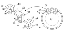
従来、モータの構成部材として、鋼といった磁性材料からなるコアの外周に巻線を巻回してなるコイルを配したローターやステーターが広く知られている。ローターやステーターは、円環状のものが汎用されている。例えば、図6(B)に示すように複数の分割コア100とコイルcとを有する分割ステーターmを複数用意し、これら分割ステーターmを環状に配置して環状部材Rにより環状に保持したステーターがある(特許文献1参照)。図6(A)に示す分割コア100は、複数のT字状の鋼板を積層させたT字状体であり、巻線が巻回される直方体状のティース101と、ティース101の両方の周縁から突出して対向配置されるヨーク102及び鍔103とからなる。分割コア100において巻線との接触箇所、主としてティース101の外周には、コア100と巻線とをより確実に絶縁するためにインシュレータ110を配置する。インシュレータ110は、二つの分割片を組み合わせて一体に構成され、ティース101の外周を覆う筒部111と、筒部111の両方の周縁から突出して対向配置される一対のフランジ112,113とからなる。フランジ112,113は、ヨーク102、鍔103に沿って配置される。筒部111の外周面と、フランジ112におけるフランジ113との対向面と、フランジ113におけるフランジ112との対向面とでつくられる]状の空間にコイルを収納する。
2. Description of the Related Art Conventionally, a rotor or a stator in which a coil formed by winding a winding around an outer periphery of a core made of a magnetic material such as steel is widely known as a constituent member of a motor. Annular rotors and stators are widely used. For example, as shown in FIG. 6 (B), a plurality of split stators m each having a plurality of
分割ステーターmは、ステーターに組み立てる際、ティース101をつくる鋼板の積層方向側がコイルエンド側、積層方向と直交する側がコイルサイド側となるように円環状に配置される。コイルサイド側とは、分割ステーターmをステーターに組み立てる際、異なる分割ステーターと隣接する側(図6(A)においてヨーク102及び鍔103が突出している側)を言い、この側に配置される面をコイルサイド面と呼ぶ。コイルエンド側とは、モータの回転軸Cm方向に向いている側(図6(B)において正面に見えている側)を言い、この側に配置される面をコイルエンド面と呼ぶ。各コア100に巻回された巻線の端部は、バスバー部材(給電用部材)に接続する。バスバー部材は、円環状に配置した分割コアの内周側及び外周側に配置される(特許文献1図11,12参照)。従って、各コア100の巻線の端部は、その内周側及び外周側に取り出す。巻線の端部とバスバー部材との接続は、通常、コイルエンド側で行う。
When the stator m is assembled to the stator, the split stator m is arranged in an annular shape so that the lamination direction side of the steel sheets forming the
その他、分割コアとして、図7に示すようにティース121の全周に亘ってヨーク122が突出されたものが開発されてきている(特許文献2参照)。この分割コア120は、図6(A)に示す分割コア100と比較して、ヨーク122における磁路面積(ヨーク122のコイルサイド面122sの面積)が大きいことから、モータに利用した場合、トルクを向上できる。
In addition, as a split core, one in which a
しかし、図7に示すようなティースの全周に亘って、その外周面から突出するようにヨークを具える分割コアでは、コイルを形成するにあたり、巻線の始端部をティース(インシュレータ)に配置させにくい場合がある。 However, in the split core having the yoke so as to protrude from the outer peripheral surface over the entire circumference of the tooth as shown in FIG. 7, when forming the coil, the starting end of the winding is disposed on the tooth (insulator). It may be difficult to do.
図7に示す分割コア120のコイルエンド側においてヨーク122は、ティース121の外周面から突出しているのに対し、鍔側(内周側(図7において下方側))は、ティース121の外周面と面一である。従って、巻線の始端部は、コイルエンド側において鍔側からであれば容易に導入できる。例えば、分割コア120に図6に示すようなインシュレータ110を配置する場合、フランジ113に切欠きを設けて巻線を導入する。また、巻線を多層に巻回してその高さがヨークの突出高さと同程度となることで、巻線の終端部をヨーク側から容易に取り出せる。従って、巻線の各端部をそれぞれ、分割コア120の内周側、外周側に配置できる。しかし、フランジ113の厚さが薄いと、自動巻線機により巻回を行う場合、巻回時の力によっては切欠きから割れなどが生じる恐れがある。また、モータの組立作業性、例えば、環状に配置した分割コア120の内周側にローターを配置する場合にローターの挿入方向などを考慮すると、巻線の両端部は、ヨーク側に配置することが望まれる。しかし、巻線の両端部をヨーク側に配置することを望む場合、図7に示す分割コア120では、突出したヨークが邪魔であり、巻線の始端部をヨーク側から導入させ難い。また、仮にヨーク側から巻線の始端部を配置させても、巻線を多層に整列巻きする場合、第一層目の第一ターンをつくる巻線に連なる始端部が各層をつくる巻線と接触して(干渉して)、ターン数が減る。
On the coil end side of the
例えば、図8に示すティース121の一方のコイルサイド面121sから巻線を巻回し始め、巻線を多層に整列巻きする場合を考える。ティース121の一方の周縁側(図8では上面側)、つまり、ヨークとの境界に接するように巻線を配置してティース121の外周面に沿って巻回し、ティース121の他方の周縁側(図8では底面側)、つまり、鍔との境界で折り返す、又はティース121の一方の周縁側で折り返す、というように巻線を巻回することで占積率を高められる。しかし、例えば、コイルエンド面121eに配置された第二層目の第nターンをつくる巻線t2-nをコイルサイド面121sに配置された第一層目の第一ターンをつくる巻線t1-1と第二ターンをつくる巻線t1-2との上に積もうとすると、巻線t2-nが巻線t1-1に連なる始端部tsと接触して、積層できない。第二層目以降の巻線についても同様に始端部tsと接触する。そこで、巻線の始端部と各層をつくる巻線とが接触しないように、各層をつくる巻線を始端部から離して巻回することが考えられる。しかし、この場合、ターン数が減ってトルクの低下を招く。この問題は、巻線を1本ずつ巻回する場合だけでなく、2本以上同時に巻回する場合も生じる。なお、図8では、説明のため、ティース121の途中で折り返し、他方の周縁側で折り返していない。また、図8は、ティース部分のみを示す。
For example, consider a case where winding is started from one
そこで、本発明の主目的は、ティースの全周に亘って突出したヨーク部を具える分割コアにおいて、巻線の両端部をヨーク部側に容易に配置可能なモータ用分割コアを提供することにある。 SUMMARY OF THE INVENTION Accordingly, a main object of the present invention is to provide a split core for a motor in which both ends of a winding can be easily arranged on the yoke part side in a split core having a yoke part protruding over the entire circumference of a tooth. It is in.
本発明は、ヨーク部において、ティースとの境界近傍に巻線の始端部を配置するための切欠き部を具えることで上記目的を達成する。具体的には、本発明は、外周に巻線が多層に巻回されるティースと、このティースの全周に亘ってその一方の周縁から突出して設けられるヨーク部とを具えるモータ用分割コアである。特に、本発明コアは、ヨーク部のコイルエンド側において、ティースとの境界近傍に、ティースの外周面と面一である切欠き部を具える。 The present invention achieves the above object by providing a notch for arranging the start end of the winding near the boundary with the tooth in the yoke. Specifically, the present invention relates to a motor split core comprising a tooth having windings wound in multiple layers on the outer periphery, and a yoke portion provided so as to project from one peripheral edge of the entire circumference of the tooth. It is. In particular, the core of the present invention includes a notch portion that is flush with the outer peripheral surface of the tooth near the boundary with the tooth on the coil end side of the yoke portion.
本発明コアは、コイルエンド側に配置されるヨーク部の一部に切欠き部を具え、この切欠き部に巻線の始端部を配置する。特に、この切欠き部は、ティースとヨーク部との境界近傍に設け、かつティースの外周面と面一とする。このような切欠き部に巻線の始端部を配置することで、切欠き部に配置した巻線の始端部に連なり、第一層目の第一ターンをつくる巻線(巻き始めとなる巻線)をティースに容易に引き出せ、ティースの外周面に沿って巻線を巻回できる。また、切欠き部に配置された巻線の始端部は、ティースとヨーク部との境界よりもヨーク部側に存在するため、巻線を多層に整列巻きする場合であっても、始端部と各層をつくる巻線とが接触しない。つまり、本発明コアは、接触防止のためにターン数を減らすことが無く、始端部の存在により占積率を低減することもない。従って、本発明コアは、巻線をヨーク部側から容易に導入することができ、かつ高占積率であるモータ構成部材を形成可能である。また、本発明コアは、図6(A)に示す従来のコアと比較して、ヨーク部における磁路面積が大きいため、通過磁束量を増大することができ、本発明コアを具えるモータは、トルクが増大する。従って、図6(A)に示す従来の分割コアを用いたモータと同じトルクを得ようとする場合、本発明コアを小さくでき、モータを小型にできる。以下、本発明をより詳しく説明する。 In the core of the present invention, a notch portion is provided in a part of the yoke portion disposed on the coil end side, and the starting end portion of the winding is disposed in the notch portion. In particular, the notch is provided near the boundary between the tooth and the yoke and is flush with the outer peripheral surface of the tooth. By arranging the starting end of the winding in such a notch, the winding that forms the first turn of the first layer is connected to the starting end of the winding arranged in the notch (the winding that is the start of winding). The wire) can be easily pulled out to the teeth, and the winding can be wound along the outer peripheral surface of the teeth. In addition, since the starting end portion of the winding disposed in the notch portion exists on the yoke portion side with respect to the boundary between the teeth and the yoke portion, even when windings are arranged in multiple layers, the starting end portion There is no contact with the windings that make up each layer. That is, the core of the present invention does not reduce the number of turns for preventing contact, and does not reduce the space factor due to the presence of the start end. Therefore, the core of the present invention can form a motor constituent member in which the winding can be easily introduced from the yoke portion side and has a high space factor. Further, since the core of the present invention has a larger magnetic path area in the yoke portion than the conventional core shown in FIG. 6 (A), the amount of magnetic flux passing through can be increased. The torque increases. Therefore, when trying to obtain the same torque as the motor using the conventional split core shown in FIG. 6 (A), the core of the present invention can be made smaller and the motor can be made smaller. Hereinafter, the present invention will be described in more detail.
本発明コアは、磁性材料から構成される磁性部材であり、外周に巻線が巻回されて、モータに利用される。このコアは、外周に巻線が巻回されるティースと、このティースの一方の周縁から突出して設けられるヨーク部とを具える。特に、ヨーク部は、ティースの全周に亘って有する。つまり、本発明コアは、ティースの外周面が全周に亘ってヨーク部よりも内側に位置する形状、端的に言うと、コイルサイド側、及びコイルエンド側のいずれから見てもT字状である。このコアは、コイルエンド側に配されるコイルエンド面と、コイルサイド側に配されるコイルサイド面とから構成される。コイルエンド側は、本発明コアにコイルを形成してモータ部品(例えば、分割ステーター)とし、このモータ部品をモータに組み立てた際、モータの回転軸Cm(図6(B)参照)方向に向いている二つの側である。そのうち、一方のコイルエンド側で巻線の端部の導入及び引き出しを行う。これら巻線の端部は、コイルに電力供給を行うバスバー部材(給電用部材)に接続される。コイルサイド側とは、本発明コアを具えるモータ部品をモータに組み立てた際、他のモータ部品に隣接する二つの側である。そして、本発明コアは、コイルをつくる巻線の始端部をヨーク部に配置するために、ヨーク部のコイルエンド側において、ティースとの境界近傍に、ティースの外周面と面一となる切欠き部を具える。つまり、ヨーク部のコイルエンド側は、ティースの外周面よりも突出した突出部分と、ティースの外周面と面一である面一部分とを有する。 The core of the present invention is a magnetic member made of a magnetic material, and a winding is wound around the outer periphery and used for a motor. The core includes a tooth around which a winding is wound on an outer periphery, and a yoke portion provided so as to protrude from one peripheral edge of the tooth. In particular, the yoke portion has the entire circumference of the teeth. That is, the core of the present invention has a shape in which the outer peripheral surface of the tooth is located on the inner side of the yoke portion over the entire circumference, in short, in a T shape when viewed from either the coil side or the coil end side. is there. The core includes a coil end surface disposed on the coil end side and a coil side surface disposed on the coil side side. On the coil end side, a coil is formed on the core of the present invention to form a motor component (e.g., a split stator), and when this motor component is assembled to a motor, the motor rotates in the direction of the rotation axis Cm (see FIG. 6 (B)). The two sides facing. Among them, the end of the winding is introduced and pulled out on one coil end side. The ends of these windings are connected to a bus bar member (power feeding member) that supplies power to the coil. The coil side is two sides adjacent to other motor components when the motor component having the core of the present invention is assembled to the motor. The core of the present invention has a notch which is flush with the outer peripheral surface of the tooth in the vicinity of the boundary with the tooth on the coil end side of the yoke portion in order to place the starting end portion of the winding forming the coil in the yoke portion. Have a department. That is, the coil end side of the yoke portion has a protruding portion that protrudes from the outer peripheral surface of the tooth, and a portion of the surface that is flush with the outer peripheral surface of the tooth.
切欠き部は、少なくとも一方のコイルエンド側に配置されるヨーク部に設ける。双方のコイルエンド側のヨーク部に切欠き部を設けた場合、いずれか一方の切欠き部を任意に選択して、巻線の始端部を配置できる。また、双方のコイルエンド側のヨーク部に切欠き部を具えて、分割コアを対称形状とすると、このコアを圧粉成形体とする場合、成形性に優れる。切欠き部をヨーク部のコイルサイド側に設けると、ヨーク部の磁路面積が低減してトルクの低下を招く。特に、分割コアのコイルサイド側においてティースとヨーク部との境界近傍は、最も磁気が集中し易い部分であり、磁路面積が大きいことが望まれる。従って、本発明コアは、できるだけヨーク部の磁路面積を低減しないようにヨーク部のコイルエンド側に切欠き部を設ける。 The notch is provided in a yoke portion disposed on at least one coil end side. When the notch portions are provided in the yoke portions on both coil ends, one of the notch portions can be arbitrarily selected and the starting end portion of the winding can be arranged. Further, if the yoke portions on both coil end sides are provided with a notch and the split core has a symmetrical shape, the moldability is excellent when the core is formed into a green compact. When the notch is provided on the coil side of the yoke, the magnetic path area of the yoke is reduced, resulting in a decrease in torque. In particular, the vicinity of the boundary between the teeth and the yoke portion on the coil side of the split core is the portion where the magnetism is most easily concentrated, and it is desired that the magnetic path area is large. Therefore, the core of the present invention is provided with a notch portion on the coil end side of the yoke portion so as not to reduce the magnetic path area of the yoke portion as much as possible.
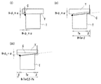
切欠き部の形状は、切欠き部の幅方向(一方のコイルサイド側から他方のコイルサイド側に向かう方向)の大きさ(以下、単に幅と呼ぶ)、及び高さ方向(ティースからヨーク部の外周側に向かう方向)の大きさ(以下、単に高さと呼ぶ)を均一的にすると、切欠き部を形成し易い。一方、切欠き部の幅や高さを段階的に、又は連続的に変化させて傾斜させた形状とすると、巻線を傾斜面に沿って配置させることができる(後述する図5(II)参照)。 The shape of the notch part is the size of the notch part in the width direction (the direction from one coil side to the other coil side) (hereinafter simply referred to as the width) and the height direction (from the teeth to the yoke part). If the size (hereinafter, simply referred to as height) of the direction toward the outer peripheral side is made uniform, it is easy to form a notch. On the other hand, when the shape is such that the width and height of the notch are inclined stepwise or continuously, the winding can be arranged along the inclined surface (FIG. 5 (II) described later) reference).
切欠き部の幅及び高さは、巻回する際の巻線数に応じて調整することが好ましい。切欠き部の面積が、巻線の大きさ(代表的には、断面積)×巻線数(本数)以上となるように切欠き部の幅及び高さを選択する。但し、切欠き部の高さが大きくなると、例えば、切欠き部の高さをヨーク部のコイルエンド側の高さと同等とする、つまり、ヨーク部の外周面側からティースに至って切欠き部を設けると、隣接するコアとでつくる磁気回路を切断して、通過磁束量を低減する恐れがある。そこで、切欠き部の高さ方向の最大の大きさは、できるだけ小さい方が好ましい。具体的には、巻線の大きさ(代表的には、線径)×巻線数(+余裕度)とすることが好ましい。切欠き部においてティースとヨーク部との境界から最も離れた部分と同境界との間の距離が巻線の線径×巻線数(+余裕度)で表わされるようにする。例えば、線径:φ1、巻線数:1、余裕度:αとする場合、図5に示すように切欠き部Cの最大高さHは、H=φ1×1+αが好ましい。高さ方向の最大の大きさを巻線の線径及び巻線数に対応した大きさとすることで、切欠き部の形成に伴うヨーク部の磁路面積の低減を減少できる。余裕度はなくてもよい。 The width and height of the notch are preferably adjusted according to the number of windings when winding. The width and height of the notch are selected so that the area of the notch is equal to or greater than the size of the winding (typically, cross-sectional area) × the number of windings (number). However, when the height of the notch portion is increased, for example, the height of the notch portion is made equal to the height of the coil end side of the yoke portion, that is, the notch portion is reached from the outer peripheral surface side of the yoke portion to the teeth. If provided, the magnetic circuit formed by the adjacent cores may be cut to reduce the amount of magnetic flux passing through. Therefore, it is preferable that the maximum size in the height direction of the notch is as small as possible. Specifically, the size of the winding (typically, the wire diameter) × the number of windings (+ the margin) is preferable. The distance between the portion of the notch that is farthest from the boundary between the teeth and the yoke and the boundary is expressed by the wire diameter x the number of windings (+ margin). For example, when the wire diameter is φ 1 , the number of windings is 1, and the margin is α, the maximum height H of the notch C is preferably H = φ 1 × 1 + α as shown in FIG. By setting the maximum size in the height direction to a size corresponding to the wire diameter and the number of windings, the reduction in the magnetic path area of the yoke portion due to the formation of the notch portion can be reduced. There may be no margin.
切欠き部の幅方向の大きさは、巻線の線径×巻線数(+余裕度)以上とすることが好ましい。例えば、線径:φ1、巻線数:1、余裕度:αとする場合、切欠き部Cの幅Wは、図5(I)に示すようにW=φ1×1+αとしてもよいが、図5(II),(III)に示すようにティースTの幅Twより大きくする、具体的には、ティースTから突出したヨーク部Yの大きさをβ、ヨーク部の幅方向の大きさをYwとするとき、W=Tw+β(図5(II))、W=Tw+2β=Yw(図5(III))とすると、始端部を安定して配置させることができ、巻回時に固定させ易い。なお、図5において矢印は、巻線の巻き始め方向を示す。 The size in the width direction of the notch is preferably equal to or greater than the wire diameter x the number of windings (+ margin). For example, when the wire diameter is φ 1 , the number of windings is 1, and the margin is α, the width W of the notch C may be W = φ 1 × 1 + α as shown in FIG. As shown in FIGS. 5 (II) and (III), the width of the yoke T is larger than the width Tw of the teeth T. Specifically, the size of the yoke Y protruding from the teeth T is β, and the width of the yoke is in the width direction. When Y is Ww, if W = Tw + β (FIG. 5 (II)) and W = Tw + 2β = Yw (FIG. 5 (III)), the starting end can be stably arranged, Sometimes easy to fix. In FIG. 5, the arrow indicates the winding start direction of the winding.
切欠き部Cは、図5(I)に示すコアのようにヨーク部Yの幅方向の一部に設ける、つまり、両コイルサイド側が開放しないように設けるよりも、図5(II),(III)に示すように少なくとも一方のコイルサイド側が開放するように設けることが好ましい。コイルサイド側が開放している場合、この開口部から巻線を導入したり、この開口部から始端部を出して端部を固定して巻線を巻回することができる。図5(III)に示すようにヨーク部Yの幅方向の全長に亘って切欠き部Cを設ける、つまり、両コイルサイド側が開放された状態となるように切欠き部Cを設けると、いずれのコイルサイド側からでも巻線を導入できる。また、図5(III)に示すコアは、対称形状となるため、圧粉成形体とする場合、成形性に優れる。 The cutout portion C is provided in a part of the yoke portion Y in the width direction like the core shown in FIG. 5 (I), that is, rather than provided so that both coil side sides are not opened, FIGS. It is preferable to provide at least one coil side as shown in III). When the coil side is open, a winding can be introduced from this opening, or the winding can be wound with the starting end protruding from this opening and fixing the end. As shown in FIG. 5 (III), when the notch portion C is provided over the entire length in the width direction of the yoke portion Y, that is, when the notch portion C is provided so that both coil side sides are opened, Winding can be introduced from the coil side. Further, since the core shown in FIG. 5 (III) has a symmetrical shape, it is excellent in moldability when formed into a green compact.
ティースは、巻線が巻回可能な種々の柱状形状が利用できる。ティースの代表的な形状として、図6(A)に示す直方体状のように、対向配置される一対の面を二組組み合わせてなる形状が挙げられる。つまり、ティースに配置されるコイルの中心軸(Cc、図示せず)と平行するように配置される四つの平行面からなる直方体状、延長面が中心軸Ccと交差するように配置される四つの交差面からなる変形四角錘台状、一対の平行面と一対の交差面とからなる四角錘台状が挙げられる。ティースを変形四角錘台状とする場合、一対の台形状面を二組組み合わせて構成する。一方の組の第一台形状面は、ヨーク部から離れるにつれて幅が広くなる面とし、他方の組の第二台形状面は、ヨーク部から離れるにつれて幅が狭くなる面とする。このような形状のティースは、ティースのヨーク部側からヨーク部と反対の側(後述する鍔側)に亘って、断面積(磁路面積)が実質的に等しくなり、磁気特性が均一的になる。ティースを四角錘台状とする場合、一対の台形状面と、一対の長方形状面とを組み合わせて構成する。この台形状面は、ヨーク部から離れるにつれて幅が狭くなる面とする。また、一対の平面と、一対の曲面とからなるティースを利用してもよい。交差面や曲面を有したティースは、スロット(巻線が配置されるスペース)内のデッドスペース(巻線が巻回できないスペース)を低減し、占積率を高めたり、巻線を巻回し易くすることができる。二組の対向配置される一対の面のうち、一方の組をコイルエンド面、他方の組をコイルサイド面とする。 As the teeth, various columnar shapes that can be wound with a winding can be used. As a typical shape of the teeth, there is a shape formed by combining two pairs of opposed surfaces such as a rectangular parallelepiped shape shown in FIG. 6 (A). In other words, a rectangular parallelepiped shape consisting of four parallel surfaces arranged so as to be parallel to the central axis (C c , not shown) of the coil arranged on the teeth, the extended surface is arranged so as to intersect the central axis C c. And a deformed square frustum shape comprising four intersecting surfaces, and a square frustum shape comprising a pair of parallel surfaces and a pair of intersecting surfaces. When the teeth are in the shape of a deformed square frustum, two pairs of trapezoidal surfaces are combined. The first trapezoidal surface of one set is a surface that increases in width as it moves away from the yoke portion, and the second trapezoidal surface of the other set is a surface that decreases in width as it moves away from the yoke portion. The teeth having such a shape have substantially the same cross-sectional area (magnetic path area) from the side of the yoke portion to the side opposite to the yoke portion (the side to be described later), and the magnetic characteristics are uniform. Become. When the teeth are in the shape of a quadrangular frustum, a pair of trapezoidal surfaces and a pair of rectangular surfaces are combined. The trapezoidal surface is a surface whose width decreases as the distance from the yoke portion increases. Moreover, you may utilize the teeth which consist of a pair of plane and a pair of curved surface. Teeth with crossed or curved surfaces reduce dead space (space where the winding cannot be wound) in the slot (space where the winding is placed), increase the space factor, and make it easier to wind the winding can do. Of the two pairs of opposed surfaces, one set is a coil end surface and the other set is a coil side surface.
本発明コアは、ティースの他方の周縁側にヨーク部と対向するように鍔部を具える構成としてもよい。鍔部は、ティースの全周に亘って設けてもよいし、部分的に設けてもよい。本発明コアは、上述のようにヨーク部に切欠き部を具えて、巻線の始端部を配置できるようにしているため、ティースの全周に亘って鍔部を設けていても問題ない。鍔部を具える場合、本発明コアは、ティースの外周面と、ヨーク部における鍔部との対向面と、鍔部におけるヨーク部との対向面とで囲まれる空間をスロットとして利用する。このコアを具えるモータ部品をモータに組み立てる際、ヨーク部を外周側に配し、鍔部を内周側に配置する。 This invention core is good also as a structure which provides a collar part so that the yoke part may be opposed to the other peripheral side of teeth. A collar part may be provided over the perimeter of teeth, and may be provided partially. Since the core of the present invention has the notch portion in the yoke portion as described above so that the starting end portion of the winding can be disposed, there is no problem even if the collar portion is provided over the entire circumference of the teeth. In the case where the collar portion is provided, the core of the present invention uses a space surrounded by the outer peripheral surface of the tooth, the surface facing the collar portion of the yoke portion, and the facing surface of the collar portion facing the yoke portion as a slot. When assembling the motor component having this core into the motor, the yoke portion is disposed on the outer peripheral side, and the flange portion is disposed on the inner peripheral side.
本発明コアを形成する磁性材料は、鉄系材料、特に、鉄や鋼といった軟磁性材料が挙げられる。このような磁性材料からなる板材の積層体や粉末を用いた圧粉成形体、或いはこれら板材の積層体と圧粉成形体との組み合せ物により、本発明コアを形成できる。特に、本発明コアは、ティースの全周に亘ってヨーク部が突出しており、かつコイルエンド側において切欠き部を具えるといった複雑な形状であるため、圧粉成形体とすると、容易に製造できて好ましい。圧粉成形体は、所定形状の金型に磁性材料の粉末を充填して加圧して製造する。磁性材料の粉末に更に絶縁材料を混合して各粉末表面に絶縁被膜を形成した被覆粉末を用いた圧粉成形体とすると、電気抵抗を高めて、渦電流の発生に伴う損失を低減できる。上記絶縁材料としては、リン酸塩系の無機材料などが挙げられる。圧粉成形体は、磁気の方向性が一定である板材の積層体と比較して、磁気の方向性の自由度が大きいといった磁気特性に優れている。 Examples of the magnetic material forming the core of the present invention include iron-based materials, particularly soft magnetic materials such as iron and steel. The core of the present invention can be formed by a laminate of plate materials made of such a magnetic material, a green compact using powder, or a combination of a laminate of these plate materials and a green compact. In particular, the core of the present invention has a complicated shape in which the yoke portion protrudes over the entire circumference of the teeth and a notch portion is provided on the coil end side. This is preferable. The green compact is manufactured by filling a metal mold of a predetermined shape with powder of a magnetic material and pressing it. If a powder compact using a coating powder in which an insulating material is further mixed with a magnetic material powder to form an insulating coating on the surface of each powder, the electrical resistance can be increased and the loss associated with the generation of eddy currents can be reduced. Examples of the insulating material include phosphate-based inorganic materials. The compacted body is excellent in magnetic characteristics such as a greater degree of freedom in the direction of magnetism than a laminate of plate materials having a constant direction of magnetism.
本発明コアと巻線とをより確実に絶縁できるように、本発明コアにおける巻線との接触箇所、主としてティースの外周面を覆うようにインシュレータを配置することが好ましい。本発明コアは、いずれか一方のコイルエンド側に設けられた切欠き部に巻線を配置するため、インシュレータは、少なくとも巻線を配置するコイルエンド側の切欠き部を覆うように形成する。即ち、本発明コアのコイルエンド側に配置するインシュレータは、ティースの外周面を覆う主被覆部と、切欠き部の外周面を覆う副被覆部とを具えるように形成する。 It is preferable to arrange the insulator so as to cover the contact portion of the core of the present invention with the winding, mainly the outer peripheral surface of the teeth, so that the core of the present invention and the winding can be insulated more reliably. In the core of the present invention, since the winding is disposed in the notch provided on either one of the coil ends, the insulator is formed so as to cover at least the notch on the coil end where the winding is disposed. That is, the insulator disposed on the coil end side of the core of the present invention is formed so as to include a main cover portion that covers the outer peripheral surface of the tooth and a sub cover portion that covers the outer peripheral surface of the notch portion.
ここで、巻線を多層に巻回する場合、ティースの一方の周縁近傍、つまりヨーク部とティースとの境界近傍と、ティースの他方の周縁近傍とで層替えを行うと、ターン数が多くなり、占積率が高められる。また、巻線を多層に巻回する場合、n層の巻線の巻回方向と次のn+1層の巻線の巻回方向とが逆方向となるように巻回する。そのため、n+1層目をつくる第一ターンの巻線は、n層目の巻き方向に倣って巻きずれが生じ易い。そこで、ヨーク部とティースとの境界で層替えを行うにあたり、ティースから突出しているヨーク部をあたり止めとして利用すると、巻きずれを防止できる。ヨーク部においてあたり止めとして利用する箇所、代表的には、ティースと連なる接続面(鍔部を具える場合、鍔部と対向する面)を覆うようにインシュレータを形成することが好ましい。具体的には、ティースの外周面を覆う部分からヨーク部の突出方向に沿って突出した部分を具えるインシュレータを形成する。コイルサイド側や切欠き部を設けていないコイルエンド側では、インシュレータにおいてヨーク部の突出部分に沿って設けた部分をあたり止めとして利用できる。しかし、切欠き部においてヨーク部の突出部分は、ヨーク部とティースとの境界から離れて(後退して)存在するため、ヨーク部の突出部分に沿ってインシュレータを設けても、この部分をあたり止めとして利用できない。そこで、主被覆部と、主被覆部に連なる副被覆部との境界にフランジ部を形成する。 Here, when the winding is wound in multiple layers, the number of turns increases if layer switching is performed near one edge of the teeth, that is, near the boundary between the yoke portion and the teeth, and near the other edge of the teeth. , Increase the space factor. When winding the winding in multiple layers, the winding is performed so that the winding direction of the n-layer winding is opposite to the winding direction of the next n + 1 layer winding. For this reason, the winding of the first turn that forms the (n + 1) th layer tends to cause a winding shift following the winding direction of the nth layer. Therefore, when the layer is changed at the boundary between the yoke portion and the tooth, the winding deviation can be prevented by using the yoke portion protruding from the tooth as a stop. It is preferable to form the insulator so as to cover a portion used as a stopper in the yoke portion, typically, a connection surface (surface facing the collar portion when the collar portion is provided) connected to the teeth. Specifically, an insulator including a portion protruding from the portion covering the outer peripheral surface of the teeth along the protruding direction of the yoke portion is formed. On the coil side side or the coil end side where the notch is not provided, a portion provided along the protruding portion of the yoke portion in the insulator can be used as a stopper. However, since the protruding portion of the yoke portion in the notch portion is separated (retracted) from the boundary between the yoke portion and the tooth, even if an insulator is provided along the protruding portion of the yoke portion, Cannot be used as a stop. Therefore, a flange portion is formed at the boundary between the main covering portion and the sub-covering portion connected to the main covering portion.
主被覆部と副被覆部との境界の一部にのみフランジ部を設ける場合、同境界においてフランジ部が形成されていない箇所から副被覆部に配置した巻線を主被覆部に引き出せる。同境界の全部に亘ってフランジ部を設けると、ティースのほぼ全周に亘ってあたり止めが存在するが、この場合、副被覆部に配置した巻線の始端部を主被覆部に引き出せるように、フランジ部に巻線の導入溝を設ける。導入溝は、例えば、主被覆部側を開口させ、この開口部から副被覆部に巻線を配置可能なように設ける。 When the flange portion is provided only at a part of the boundary between the main cover portion and the sub cover portion, the winding disposed in the sub cover portion can be drawn out from the portion where the flange portion is not formed at the boundary to the main cover portion. If the flange part is provided over the entire boundary, there is a stop around almost the entire circumference of the tooth. In this case, the starting end part of the winding arranged in the sub-coating part can be pulled out to the main covering part. The winding groove is provided in the flange portion. The introduction groove is provided so that, for example, the main covering portion side is opened, and the winding can be arranged from the opening portion to the sub covering portion.
ティースの外周に配置するインシュレータの厚さは、できる限り薄くして、コア部分が大きくなるようにすると、トルクの増大、小型化という優れた効果に加えて、発熱したコイルの熱をコアに伝え易くなり、モータの放熱特性をも向上できる。また、インシュレータには、巻線を整列配置させ易いように巻線を嵌合する嵌合溝を設けてもよい。 When the thickness of the insulator placed on the outer periphery of the teeth is made as thin as possible and the core portion is made large, in addition to the excellent effects of increasing torque and downsizing, the heat of the generated coil is transmitted to the core. This makes it easier to improve the heat dissipation characteristics of the motor. Further, the insulator may be provided with a fitting groove for fitting the windings so that the windings are easily arranged and arranged.
インシュレータを形成する絶縁材料としては、PPS(Poly Phenylene Sulfide ポリフェニレンスルフィド)、LCP(Liquid Crystal Polymer 液晶ポリマー)などの樹脂が挙げられる。上記樹脂にガラス(二酸化珪素)、アルミナ(酸化アルミニウム)、酸化チタンなどの無機充填剤を添加させてインシュレータを形成すると、インシュレータ自体の放熱性を向上できる。また、インシュレータは、分割片を組み合わせて一体となるように構成とすると、コアの外周に配置し易い。分割片同士の接合部分は、コイルエンド側に配置することが好ましい。 Examples of the insulating material forming the insulator include resins such as PPS (Poly Phenylene Sulfide polyphenylene sulfide) and LCP (Liquid Crystal Polymer liquid crystal polymer). When an insulator is formed by adding an inorganic filler such as glass (silicon dioxide), alumina (aluminum oxide), or titanium oxide to the resin, the heat dissipation of the insulator itself can be improved. Further, when the insulator is configured so as to be integrated by combining the divided pieces, it is easy to arrange the insulator on the outer periphery of the core. It is preferable to arrange the joint portion between the split pieces on the coil end side.
上記構成を具える本発明コアは、モータを構成する分割ステーターなどのモータ部品に好適に利用できる。モータ部品は、本発明コアのティース(インシュレータ)の外周に巻線を巻回することで得られる。特に、巻線を多層に整列巻きしてコイルを形成することで、占積率を向上できる。巻線は、丸線の他、角線などの種々のものが利用できる。 The core of the present invention having the above configuration can be suitably used for a motor component such as a divided stator that constitutes a motor. The motor component is obtained by winding a winding around the outer periphery of the tooth (insulator) of the core of the present invention. In particular, the space factor can be improved by forming the coils by winding the windings in multiple layers. As the winding, various types such as a square wire as well as a round wire can be used.
上記モータ部品を所定数用意し、これらモータ部品を環状に配置し、環状部材を用いて環状に保持することで、例えば、アウター型ローターや、インナー型ローターのモータのステーターに利用できる。環状に配された各モータ部品は、コイルをつくる巻線端部を接続し、集中巻き構造とすることが好ましい。 By preparing a predetermined number of the motor parts, arranging the motor parts in an annular shape, and holding them in an annular shape using an annular member, the motor parts can be used, for example, as an outer type rotor or an inner type rotor motor stator. Each motor component arranged in an annular shape preferably has a concentrated winding structure by connecting winding ends that form a coil.
本発明モータ用分割コアは、ティースの全周に亘って突出するヨーク部を具えていながら、ヨーク部側から巻線の始端部を容易に導入することができる。従って、本発明コアは、巻線の両端部をヨーク部側に配置させることができる。 The motor split core according to the present invention can easily introduce the starting end portion of the winding from the yoke portion side while including the yoke portion protruding over the entire circumference of the teeth. Therefore, in the core of the present invention, both end portions of the winding can be arranged on the yoke portion side.
以下、本発明の実施の形態を図に基づいて説明する。
<分割コア>
図1(I)は、本発明モータ用分割コアの斜視図、(II)は、本発明コアをコイルエンド側から見た図、(III)は、本発明コアをコイルサイド側から見た図である。分割コア10は、柱状のティース11と、ティース11の一方の周縁から突出して設けられるヨーク部12とを具える。ヨーク部12は、ティース11の全周に亘ってティース11と一体に設けられている。ティース11の外周には、図示しないインシュレータ(後述)が配置され、このインシュレータの上に巻線が巻回されて分割ステーターを構成する。このような分割ステーターを複数用意し、各分割ステーターのヨーク部12の一面(コイルサイド面12s)を接触させて円環状に配置し、環状部材を用いてこれら分割ステーターを一体にしてモータステーターを構成する。分割ステーター及び分割コアにおいて、モータステーターを組み立てた際、他の分割ステーターに隣接する側がコイルサイド側、隣接しない側がコイルエンド側である。
Hereinafter, embodiments of the present invention will be described with reference to the drawings.
<Split core>
FIG. 1 (I) is a perspective view of a split core for a motor of the present invention, (II) is a view of the core of the present invention as viewed from the coil end side, and (III) is a view of the core of the present invention as viewed from the coil side. It is. The
分割コア10の最も特徴とするところは、ティース11の外周面から突出しているヨーク部側から巻線を導入するにあたり、巻線の始端部をヨーク部12に配置できるように、ヨーク部12の一部を切り欠いている点にある。具体的には、図1に示すようにヨーク部12のコイルエンド側において、ティース11とヨーク部12との境界15近傍を切り欠いている。切り欠いた箇所(切欠き部12t)は、ティース11の外周面(コイルエンド面11e)と面一である。つまり、ヨーク部12のコイルエンド側は、ティース11の外周面よりも高い突出部分12eと、ティース11の外周面と同じ高さである切欠き部12tとが存在する。
The most distinctive feature of the
切欠き部12tは、コイルエンド側におけるヨーク部12の幅Ywと同じ幅で設けられた帯状の切欠きであり、両コイルサイド側が開口している。従って、いずれの側からでも巻線を導入することができる(図1(II)では、右方のコイルサイド側から巻線を導入している例を示す)。また、巻線の巻回時、巻線の始端部を開口部から引き出して固定しておくことができる。切欠き部12tの高さ方向の大きさ(高さ)hは、巻線の線径×巻線数としている。切欠き部12tをコイルエンド側に設けると共に、高さhをできるだけ小さくしていることで、ヨーク部12のコイルサイド面12sを大きくして、ヨーク部12における磁路面積を大きくすることができる。このような切欠き部12tを設けたことで、コイルエンド側においてヨーク部の突出部分12eは、ティース11とヨーク部12との境界15から高さh分だけ後退して存在する。
The
ティース11は、対向配置される一対の台形状面と、対向配置される一対の長方形状面とから構成される。台形状面は、ヨーク部12から離れるに従って幅を狭くしている。コイルエンド面11eを台形状面、コイルサイド面11sを長方形状面としている。ティース11の他方の周縁側でコイルサイド側には、ヨーク部12と対向するように鍔部13を具える。このような分割コア10は、軟磁性材料からなる粉末を用いた圧粉成形体である。圧粉成形体とすることで、複雑な形状の分割コア10を簡単に成形できる。切欠き部は、いずれか一方のコイルエンド側に設ければよいが、分割コア10のように両コイルエンド側に具えた対称形状とすると、成形性に優れることに加えて、いずれの切欠き部に巻線の始端部を配置するかを任意に選択できる。
The
分割コア10にヨーク部側から巻線を導入して、ティース11に巻線を多層に整列巻きする手順の一例を説明する。図2において、丸印は、巻線を示し、丸印内の数字(x-y)は、第x層目の第yターンを示す。ヨーク部12のコイルエンド側において一方のコイルサイド側(図2において左方側)から巻線の始端部tsを引き出して切欠き部12tに配置し、切欠き部12tにおける他方のコイルサイド側(同右方側)の開口部からその端部を引き出して固定する。始端部tsに繋がる巻線は、ティースの一方のコイルサイド側に配置し、第一層目の第一ターンをつくる巻線t1-1とする。以下、ティース11の外周面に沿って鍔部13に至るまで整列巻きを行い、第一層目を形成する(図2では四ターンで第一層目を形成する)。鍔部13で巻線を折り返して第二層目を形成する。第二層目の第三ターンをつくる巻線t2-3を第一層目の第一ターンをつくる巻線t1-1と第二ターンをつくる巻線t1-2との上に配置させる。このとき、分割コア10では、始端部tsを切欠き部12tに配置させていることで、巻線t2-3が始端部tsに接触することなく巻線t1-1と巻線t1-2との上に積層できる。また、第二層目の最終ターン(第四ターン)をつくる巻線t2-4をヨーク部12に接するように配置することができる。従って、ヨーク部12近傍で巻線を折り返して第三層目を形成することができる。以下、同様に巻線を巻回して、第三層目以降を形成する。巻回後、固定していた始端部tsの端部は、突出部分12e側に折り曲げて、ヨーク部12の外周側に引き出す。なお、図2では、説明のために巻線を強調している。
An example of a procedure for introducing windings into the
分割コア10は、ヨーク部側から巻線の始端部を導入し、奇数層目の第一ターンをつくる巻線、及び偶数層目の最終ターンをつくる巻線の双方をティース11とヨーク部12との境界15近傍に沿って配置させ、多層に整列巻きを行える。そのため、分割コア10を利用することで、高占積率のモータが得られる。また、分割コア10は、上述のようにヨーク部の磁路面積が大きいことから、分割コア10を利用すると、高トルクのモータが得られる。或いは、同じトルクのモータを作製する場合、コアの大きさを小さくすることができるため、モータを小型にできる。更に、分割コア10は、ヨーク部側から巻線を導入し、ヨーク部側から巻線を取り出すことができる、即ち、巻線の両端部をヨーク部側に配置可能なため、バスバー部材の接続などをヨーク部の外周側のみで行える。
The
なお、図2では、巻線数を1本としたが、巻線数を2本以上としてもよい。巻回作業の際、巻線の始端部は、固定させておく。また、巻線において始端部や終端部は、バスバー部材に接続されて、始端部や終端部に繋がるコイルを形成する巻線部分に電力を供給するために利用する部分であり、コイルの巻き数(ターン数)に含まれない部分である。 In FIG. 2, the number of windings is one, but the number of windings may be two or more. During the winding operation, the starting end of the winding is fixed. In addition, the start and end portions of the winding are portions used to supply power to the winding portion that is connected to the bus bar member and forms the coil connected to the start and end portions. It is a part not included in (number of turns).
分割コア10と巻線とをより確実に絶縁するために、分割コア10において巻線との接触箇所には、インシュレータを配置することが好ましい。以下、インシュレータを説明する。
In order to more reliably insulate the
<インシュレータ1>
図3は、本発明分割コアにインシュレータを配置した状態を示す図であり、(I)は、コイルエンド側から見た図、(II)は、コイルサイド側から見た図、(III)は、切欠き部近傍を示す部分斜視図である。分割コア10において巻線と接触する箇所、或いは接触する可能性が高い箇所としては、ティースの外周面、コイルサイド側においてヨーク部における鍔部との対向面及び鍔部におけるヨーク部との対向面が挙げられる。特に、分割コア10は、いずれか一方のコイルエンド側に設けられた切欠き部に巻線の始端部を配置させるため、この切欠き部も巻線との接触箇所となる。そこで、分割コア10に配置するインシュレータ20は、ティースの外周面を覆う筒状部21と、コイルサイド側においてヨーク部12における鍔部との対向面を覆うサイドフランジ部22と、鍔部13におけるヨーク部との対向面を覆う鍔側フランジ部23と、巻線の始端部が配置される一方のコイルエンド側において切欠き部を覆う切欠被覆部(副被覆部)24とを具える。
<
FIG. 3 is a view showing a state in which an insulator is arranged in the split core of the present invention, (I) is a view seen from the coil end side, (II) is a view seen from the coil side side, and (III) is a view It is a fragmentary perspective view which shows the notch part vicinity. Locations of the
筒状部21において、コイルサイド側の面、及びコイルエンド側の面の一部に巻線を整列させ易いように嵌合溝を設けている。サイドフランジ部22は、筒状部21の外周面から突出するように、ヨーク部12に沿って設けている。鍔側フランジ部23は、コイルサイド側だけでなく、コイルエンド側にも延長して設けている。つまり、鍔側フランジ部23は、筒状部21の鍔部側において筒状部21の全周に亘って設けられた環状形状であり、分割コア10の鍔部13において内周側面(図3において下面)が露出された状態である。切欠被覆部24は、筒状部21の一方のコイルエンド側の面(主被覆部)に連なって一体に形成されている。この切欠被覆部24に連なってヨーク部12の突出箇所を覆うようにヨークフランジ部25を設けており、巻線の始端部がコア10に接触しないようにしている。このコイルエンド側に配置された巻線の始端部や終端部をヨーク部12の外周側(図3(I)において上側)に配置するため、ヨーク部12のコイルエンド側の面が巻線と接触しないように、インシュレータ20は、この面を覆うヨーク被覆部26を具える。
In the
巻線を多層に巻回する場合、ヨーク部近傍又は鍔部近傍で層替えを行う。このとき、サイドフランジ部22や鍔側フランジ部23をあたり止めとして利用できるように、これらフランジ部22,23は、筒状部21に直交するように設けている。あたり止めを利用することで、巻線の巻きずれなどが生じ難く、巻きずれに伴う占積率の低下などを防止できる。層替えをより確実に行えるようにするには、コイルエンド側にもあたり止めが存在することが望まれる。そこで、インシュレータ20は、筒状部21のコイルエンド面からヨーク部の突出方向に沿って突出し、切欠被覆部24と筒状部21のコイルエンド側の面との境界の全部に亘ってフランジ部27を具える。このフランジ部27は、図3(I)に示すように一方のコイルサイド側近傍に設けず、切欠き被覆部24に巻線が配置できるようにし、この巻線配置スペース分を除いて、ヨーク部12のコイルエンド側の幅とほぼ同じ幅に設けている。また、このフランジ部27の他方のコイルサイド側は、サイドフランジ部22に接続させている。図3(II)に示すように巻線の始端部を配置しない他方のコイルエンド側にもフランジ部27を設けており、このフランジ部27は、両コイルサイド側をサイドフランジ部22に接続させている。フランジ部27も筒状部21と直交するように設けている。また、インシュレータ20は、このフランジ部27に連続してヨーク被覆部26を設けている。
When the winding is wound in multiple layers, the layer is changed in the vicinity of the yoke portion or the flange portion. At this time, the
サイドフランジ部22,鍔側フランジ部23に加えて、このようなフランジ部27を具えることで、インシュレータ20は、筒状部21のほぼ全周に亘ってあたり止めを具える。しかし、上記境界にフランジ部27が存在することで、切欠被覆部24に配置した巻線の始端部を筒状部21側に引き出せない。そこで、フランジ部27には、切欠被覆部24に配置した巻線の始端部を筒状部21側に取り出せるように、一方のコイルサイド側から、他方のコイルサイド側の筒状部21近傍に亘って導入溝28を設けている。導入溝28は、筒状部側(図3(II)では、下方側)が開口している。従って、巻線の始端部は、図3(II)の矢印で示すように筒状部21に沿って下方側から導入溝28に嵌め込める。巻回作業を行う場合、巻線200の始端部を導入溝28に嵌め込み、コイルサイド側の開口部から巻線200の始端部を引き出した状態で端部を固定して、巻線200を巻回する。そして、巻回後、ヨークフランジ部25及びヨーク被覆部26に沿って巻線200の始端部を折り曲げて、ヨーク部12の外周側に配置させる。
By providing such a
このようなインシュレータ20を分割コア10に配置することで、巻線との絶縁を確実に行えると共に、巻線の始端部を切欠き部(切欠き被覆部)に配置させることができる。また、インシュレータ20は、筒状部21の両縁部において、そのほぼ全周に亘ってあたり止め(フランジ部27、サイドフランジ部22、鍔側フランジ部23)を具えており、層替えの際の巻きずれを効果的に防止できる。
By disposing such an
なお、インシュレータ20は、二つの分割片を組み合わせて一体にする構成であり、分割コア10に簡単に配置できる。本例では、分割片の合わせ目がコイルエンド側に配置される分割片としたが、コイルサイド側に合わせ目が配置される分割片としてもよい。また、インシュレータ20は、巻回作業中、分割コアから脱落し難いように掛止部29を具える。掛止部29は、ヨークフランジ部25と対向するように設け、掛止部29とヨークフランジ部25とでヨーク部12を挟持するように配される。掛止部29は、一方のコイルエンド側のみに設けているが、両方のコイルエンド側に設けてもよい。掛止部29を設ける代わりに接着剤でインシュレータ20を固定してもよい。その他、インシュレータ20の筒状部21に、その全周に亘って段差を設けてもよい。段差を設けることで、コイルの外周面を段差のない平滑な面とすることができる。これら三つの点は、後述するインシュレータ2についても同様である。
The
<インシュレータ2>
図4は、本発明分割コアに別のインシュレータを配置した状態を示す図であり、切欠き部近傍を示す部分斜視図である。インシュレータ30の基本的構成は、図3に示すインシュレータ20と同様である。つまり、インシュレータ30は、分割コア10のティースの外周面を覆う筒状部31と、コイルサイド側においてヨーク部12における鍔部との対向面を覆うサイドフランジ部32と、鍔部13におけるヨーク部との対向面を覆う鍔側フランジ部33と、巻線の始端部が配置される一方のコイルエンド側において切欠き部を覆う切欠被覆部34とを具える。鍔側フランジ部33は、筒状部31の鍔部側において筒状部31の全周に亘って設けられている。筒状部31のコイルサイド側の面、及びコイルエンド側の面の一部には、巻線の嵌合溝を設けている。切欠被覆部34は、筒状部31の一方のコイルエンド側の面(主被覆部)に連なって一体に形成されている。また、インシュレータ30は、切欠被覆部34に連なってヨーク部12の突出箇所を覆うヨークフランジ部35と、ヨーク部12のコイルエンド側の面を覆うヨーク被覆部36とを具える。このインシュレータ30は、二つの分割片を組み合わせて一体にする構成である。
<
FIG. 4 is a diagram showing a state in which another insulator is arranged on the split core of the present invention, and is a partial perspective view showing the vicinity of a notch. The basic configuration of the
そして、インシュレータ30は、切欠被覆部34と筒状部31のコイルエンド側の面との境界の一部にフランジ部37を具えている。つまり、巻線の始端部が配置される一方のコイルエンド側において上記境界には、フランジ部37が存在する部分と存在しない部分とが存在する。巻線の始端部を配置するコイルエンド側にこのようなフランジ部37を設けることで、上記フランジ部37が存在しない部分から、切欠被覆部34に配置した巻線の始端部を筒状部31側に簡単に取り出すことができる。巻線の始端部を配置しない他方のコイルエンド側には、インシュレータ20と同様にヨーク部12と同幅にフランジ部を設けている(図示せず)。
The
巻線の始端部を配置するコイルエンド側のフランジ部37は、ヨーク部12の突出方向における厚さを段階的に変化させている。具体的には、一方のコイルサイド側(図4において右方側)から他方のコイルサイド側(同左方側)に向かって段階的に厚さを薄くした傾斜面を有する。このように右方側を厚く、左方側を薄い板状となるように形成することで、フランジ部37は、ヨーク部12の突出した側が開口した導入溝を有する形状となる。この導入溝に対して、図4の矢印で示すようにヨーク部12に向かって差し入れるようにして巻線200の始端部を嵌め込むことができ、巻線200の始端部を配置し易い。フランジ部37において薄い板状の部分の厚みは、スロットの体積をできるだけ大きくする場合、できるだけ薄くすることが望まれる。このとき、フランジ部37は、肉厚部分を有することで強度を高めて、あたり止めとして利用する際に変形したり、割れたりすることを抑制する。巻回作業を行う場合、巻線200の端部を上記導入溝に差し入れ、フランジ部37の傾斜面に沿って巻線200の始端部を配置し、ヨーク被覆部36に沿って折り曲げて、ヨーク部12の外周側に配置させて固定して、巻線200を巻回する。
The
なお、上述した実施形態は、本発明の要旨を逸脱することなく、適宜変更することが可能であり、上述した構成に限定されるものではない。例えば、両コイルエンド側において切欠被覆部及び導入溝を具えるインシュレータとしてもよい。 The above-described embodiment can be appropriately changed without departing from the gist of the present invention, and is not limited to the above-described configuration. For example, it is good also as an insulator which provides a notch coating | coated part and an introductory groove in both coil end sides.
本発明モータ用分割コアは、ステーターといったモータの構成部材に好適に利用することができる。この分割コアを具えるモータは、電気自動車やハイブリッド自動車などの高出力が要求されるモータに好適に利用できる。 The split core for a motor of the present invention can be suitably used for a motor component such as a stator. A motor having this divided core can be suitably used for a motor that requires high output, such as an electric vehicle or a hybrid vehicle.
10 分割コア 11 ティース 11e ティースのコイルエンド面
11s ティースのコイルサイド面 12 ヨーク部 12e 突出部分
12s ヨーク部のコイルサイド面 12t 切欠き部 13 鍔部
15 ティースとヨーク部との境界 C 切欠き部 T ティース Y ヨーク部
20,30 インシュレータ 21,31 筒状部 22,32 サイドフランジ部
23,33 鍔側フランジ部 24,34 切欠被覆部 25,35 ヨークフランジ部
26,36 ヨーク被覆部 27,37 フランジ部 28 導入溝 29 掛止部
100,120 分割コア 101,121 ティース 102,122 ヨーク 103 鍔
110 インシュレータ 111 筒部 112,113 フランジ
121e ティースのコイルエンド面 121s ティースのコイルサイド面
122s ヨークのコイルサイド面
200 巻線
m 分割ステーター c コイル R 環状部材
10
11s Coil side surface of
12s Coil side surface of the
15 Boundary between teeth and yoke C Notch T Teeth Y Yoke
20,30
23,33
26,36
100,120 Split core 101,121 Teeth 102,122
110
121e Teeth
122s York coil side surface
200 windings
m Split stator c Coil R Annular member
Claims (4)
ヨーク部のコイルエンド側には、ヨーク部とティースとの境界近傍に、ティースの外周面と面一である切欠き部を具えることを特徴とするモータ用分割コア。 In a split core for a motor comprising a tooth in which a winding is wound in multiple layers on the outer periphery, and a yoke portion provided so as to protrude from one peripheral edge over the entire periphery of the tooth,
A split core for a motor, comprising a notch portion that is flush with an outer peripheral surface of a tooth near a boundary between the yoke portion and the tooth on a coil end side of the yoke portion.
このインシュレータは、
ティースの外周面を覆う主被覆部と、
主被覆部に連なり、切欠き部の外周面を覆う副被覆部と、
主被覆部からヨーク部の突出方向に沿って突出したフランジ部とを具え、
フランジ部は、主被覆部と副被覆部との境界の全部に亘って設けられ、主被覆部側が開口し、この開口部から副被覆部に巻線を配置可能な導入溝を具えることを特徴とする請求項1に記載のモータ用分割コア。 An insulator is arranged on the coil end side of the split core,
This insulator
A main covering covering the outer peripheral surface of the teeth;
A sub-covering part that is continuous with the main covering part and covers the outer peripheral surface of the notch part,
A flange portion protruding from the main covering portion along the protruding direction of the yoke portion,
The flange portion is provided over the entire boundary between the main cover portion and the sub cover portion, and the main cover portion side is provided with an introduction groove through which the winding can be arranged in the sub cover portion. 2. The split core for a motor according to claim 1, wherein the split core is for a motor.
このインシュレータは、
ティースの外周面を覆う主被覆部と、
主被覆部に連なり、切欠き部の外周面を覆う副被覆部と、
主被覆部からヨーク部の突出方向に沿って突出したフランジ部とを具え、
フランジ部は、主被覆部と副被覆部との境界の一部にのみ設けられていることを特徴とする請求項1に記載のモータ用分割コア。 An insulator is arranged on the coil end side of the split core,
This insulator
A main covering covering the outer peripheral surface of the teeth;
A sub-covering part that is continuous with the main covering part and covers the outer peripheral surface of the notch part,
A flange portion protruding from the main covering portion along the protruding direction of the yoke portion,
2. The split core for a motor according to claim 1, wherein the flange portion is provided only at a part of a boundary between the main cover portion and the sub cover portion.
Priority Applications (1)
| Application Number | Priority Date | Filing Date | Title |
|---|---|---|---|
| JP2006216293A JP2008043105A (en) | 2006-08-08 | 2006-08-08 | Split core for motor |
Applications Claiming Priority (1)
| Application Number | Priority Date | Filing Date | Title |
|---|---|---|---|
| JP2006216293A JP2008043105A (en) | 2006-08-08 | 2006-08-08 | Split core for motor |
Publications (1)
| Publication Number | Publication Date |
|---|---|
| JP2008043105A true JP2008043105A (en) | 2008-02-21 |
Family
ID=39177503
Family Applications (1)
| Application Number | Title | Priority Date | Filing Date |
|---|---|---|---|
| JP2006216293A Pending JP2008043105A (en) | 2006-08-08 | 2006-08-08 | Split core for motor |
Country Status (1)
| Country | Link |
|---|---|
| JP (1) | JP2008043105A (en) |
Cited By (7)
| Publication number | Priority date | Publication date | Assignee | Title |
|---|---|---|---|---|
| JP2008278603A (en) * | 2007-04-26 | 2008-11-13 | Sumitomo Electric Ind Ltd | Split core for motor |
| JP2009291004A (en) * | 2008-05-29 | 2009-12-10 | Toyota Motor Corp | Rotary electric machine |
| JP2010148258A (en) * | 2008-12-19 | 2010-07-01 | Yaskawa Electric Corp | Rotary electric machine and method for manufacturing the same |
| JP2016513262A (en) * | 2013-02-21 | 2016-05-12 | ザ・ボーイング・カンパニーThe Boeing Company | Magnetic core magnetic flux sensor |
| US10008896B2 (en) | 2015-02-18 | 2018-06-26 | Mitsubishi Electric Corporation | Rotary electric machine and insulator for rotary electric machine |
| WO2018168090A1 (en) * | 2017-03-14 | 2018-09-20 | 日本電産株式会社 | Stator, motor, and electric power steering device |
| WO2019003674A1 (en) * | 2017-06-26 | 2019-01-03 | 日立オートモティブシステムズ株式会社 | Dynamo-electric machine |
-
2006
- 2006-08-08 JP JP2006216293A patent/JP2008043105A/en active Pending
Cited By (12)
| Publication number | Priority date | Publication date | Assignee | Title |
|---|---|---|---|---|
| JP2008278603A (en) * | 2007-04-26 | 2008-11-13 | Sumitomo Electric Ind Ltd | Split core for motor |
| JP2009291004A (en) * | 2008-05-29 | 2009-12-10 | Toyota Motor Corp | Rotary electric machine |
| JP2010148258A (en) * | 2008-12-19 | 2010-07-01 | Yaskawa Electric Corp | Rotary electric machine and method for manufacturing the same |
| JP2016513262A (en) * | 2013-02-21 | 2016-05-12 | ザ・ボーイング・カンパニーThe Boeing Company | Magnetic core magnetic flux sensor |
| US10008896B2 (en) | 2015-02-18 | 2018-06-26 | Mitsubishi Electric Corporation | Rotary electric machine and insulator for rotary electric machine |
| WO2018168090A1 (en) * | 2017-03-14 | 2018-09-20 | 日本電産株式会社 | Stator, motor, and electric power steering device |
| JPWO2018168090A1 (en) * | 2017-03-14 | 2020-01-16 | 日本電産株式会社 | Stator, motor, electric power steering device |
| JP7060007B2 (en) | 2017-03-14 | 2022-04-26 | 日本電産株式会社 | Stator, motor, electric power steering device |
| US11342805B2 (en) | 2017-03-14 | 2022-05-24 | Nidec Corporation | Stator, motor, and electric power steering device |
| WO2019003674A1 (en) * | 2017-06-26 | 2019-01-03 | 日立オートモティブシステムズ株式会社 | Dynamo-electric machine |
| CN110785914A (en) * | 2017-06-26 | 2020-02-11 | 日立汽车系统株式会社 | Rotating electrical machine |
| JPWO2019003674A1 (en) * | 2017-06-26 | 2020-03-19 | 日立オートモティブシステムズ株式会社 | Rotating electric machine |
Similar Documents
| Publication | Publication Date | Title |
|---|---|---|
| JP5379550B2 (en) | Armature | |
| US9793774B2 (en) | Armature for rotary electric machine | |
| WO2007055210A1 (en) | Motor core part and motor part | |
| WO2010100890A1 (en) | Armature for motor | |
| JPWO2016208555A1 (en) | Electric motor stator | |
| JP5154829B2 (en) | Split core parts | |
| JP5082524B2 (en) | Insulator, stator structure and manufacturing method | |
| CN107408859B (en) | Axial-gap rotary electric machine and stator | |
| JP2008043106A (en) | Split core for motor | |
| JP2016119365A (en) | Bobbin for coil component and manufacturing method of coil component | |
| JP4964016B2 (en) | Split core for motor | |
| JP2008043105A (en) | Split core for motor | |
| JP2008167518A (en) | stator | |
| JP2009044829A (en) | Stator core for axial gap type motors | |
| JP2010011569A (en) | Stator | |
| JP4725455B2 (en) | Motor core parts | |
| WO2019102736A1 (en) | Rotating electric machine and stator | |
| JP4411950B2 (en) | Electric motor stator, manufacturing method thereof, and permanent magnet electric motor using the stator | |
| JP7139933B2 (en) | Armature and armature manufacturing method | |
| JP2004208464A (en) | Electric motor winding structure | |
| JP2013005634A (en) | Outer rotor type motor | |
| JPWO2020044428A1 (en) | stator | |
| JP2009254001A (en) | Coil and split stator equipped with this coil | |
| JP4926192B2 (en) | Electric motor stator | |
| JP7621131B2 (en) | Rotating Electric Machine |
Legal Events
| Date | Code | Title | Description |
|---|---|---|---|
| A977 | Report on retrieval |
Free format text: JAPANESE INTERMEDIATE CODE: A971007 Effective date: 20091029 |
|
| A131 | Notification of reasons for refusal |
Free format text: JAPANESE INTERMEDIATE CODE: A131 Effective date: 20091111 |
|
| A02 | Decision of refusal |
Free format text: JAPANESE INTERMEDIATE CODE: A02 Effective date: 20100311 |