JP2008123745A - Lighting lamp lighting state detection device - Google Patents
Lighting lamp lighting state detection device Download PDFInfo
- Publication number
- JP2008123745A JP2008123745A JP2006303974A JP2006303974A JP2008123745A JP 2008123745 A JP2008123745 A JP 2008123745A JP 2006303974 A JP2006303974 A JP 2006303974A JP 2006303974 A JP2006303974 A JP 2006303974A JP 2008123745 A JP2008123745 A JP 2008123745A
- Authority
- JP
- Japan
- Prior art keywords
- lighting
- information
- lighting state
- lamp
- illumination
- Prior art date
- Legal status (The legal status is an assumption and is not a legal conclusion. Google has not performed a legal analysis and makes no representation as to the accuracy of the status listed.)
- Granted
Links
Images

Landscapes
- Circuit Arrangement For Electric Light Sources In General (AREA)
Abstract
【課題】照明灯へのセンサ設置や夜間に巡回車両を走行させることなく照明灯の点灯状態または不点灯状態を検出することができる照明灯の点灯状態検出装置を提供する。
【解決手段】広域に複数個設置された照明灯の点灯状態または不点灯状態を検出する照明灯の点灯状態検出装置で、照明灯の設置箇所が、緯度・経度情報により予め設定された検出対象箇所の地図情報31、32と、検出対象箇所を上空から撮影した写真情報33と、この写真情報33と地図情報31,32とを合致させ、前記写真情報上での照明灯の点灯状態または不点灯状態と、前記地図情報に設定された照明灯の位置とを対応させて、前記照明灯毎の点灯状態または不点灯状態を検出する。
【選択図】図3An illumination lamp lighting state detection device capable of detecting a lighting condition or a non-lighting condition of an illumination lamp without installing a sensor on the illumination lamp or driving a patrol vehicle at night is provided.
An illumination lamp lighting state detection device for detecting lighting state or non-lighting state of a plurality of illumination lamps installed in a wide area, wherein the installation location of the illumination lamp is a detection target set in advance by latitude / longitude information The map information 31, 32 of the location, the photo information 33 taken from the sky of the location to be detected, and the photo information 33 and the map information 31, 32 are matched, and the lighting state of the illumination light on the photo information or not A lighting state or a non-lighting state for each of the lighting lamps is detected by associating the lighting state with the position of the lighting lamp set in the map information.
[Selection] Figure 3
Description
本発明は、道路や公園或いは河川などの広域にわたって設けられる街路灯などの照明灯の点灯状態または不点灯状態を検出できる照明灯の点灯状態検出装置に関する。 The present invention relates to an illumination lamp lighting state detection device capable of detecting a lighting state or a non-lighting state of an illumination lamp such as a street lamp provided over a wide area such as a road, a park, or a river.
一般に、道路の照明灯や、公園の照明灯、さらには河川に沿って設けられる照明灯は、広範囲にわたって多数設けられている。このような照明灯のランプ切れが生じた場合は、速やかにこれを検出し、交換などの対応策を取る必要がある。 In general, a large number of road lamps, park lamps, and lamps provided along rivers are provided over a wide area. When such an illumination lamp breaks out, it is necessary to quickly detect this and take countermeasures such as replacement.
このように広域に多数散在する照明灯のランプ切れを検出するために、従来は、夜間に巡回車両を走行させ、目視によって確認していた。しかし、このためには、巡回のための人手が必要となる。また、見落としを防ぐために、巡回車両は比較的に低速で走行させる必要がある。このため、交通渋滞や交通集中による事故を誘発する可能性があった。 In order to detect the lamp burnout of a large number of illuminating lamps scattered in a wide area as described above, conventionally, a traveling vehicle is run at night and confirmed visually. However, this requires manpower for patrol. In order to prevent oversight, the traveling vehicle needs to travel at a relatively low speed. For this reason, there was a possibility of inducing an accident due to traffic congestion or traffic concentration.
この巡回車両により、照明灯の不点灯を検出する改良案として、照明灯側に照明灯の不具合を検出するセンサーを設けて、このセンサーによる検出信号を発信させ、これを巡回車両側で検出することにより、照明灯の点灯・不点灯状態を検出することが提案されている(例えば、特許文献1、特許文献2参照)。
As an improvement plan for detecting non-lighting of the illuminating lamp by this patrol vehicle, a sensor for detecting the malfunction of the illuminating lamp is provided on the illuminating lamp side, and a detection signal is transmitted by this sensor, and this is detected on the patrol vehicle side. Thus, it has been proposed to detect the lighting / non-lighting state of the illuminating lamp (see, for example,
上記提案の前者では、照明灯それぞれに、その動作の正常、異常を検出する検出手段を設け、この検出手段による検出結果を、照明灯のそれぞれについて設定された符号と共に無線により送出する。この送出されたデータを巡回車両のような移動手段により受信することで、照明灯のランプ切れを検出している。 In the former proposed above, each illumination lamp is provided with detection means for detecting normality and abnormality of the operation, and the detection result by this detection means is transmitted wirelessly together with a code set for each of the illumination lamps. The transmitted data is received by a moving means such as a traveling vehicle, thereby detecting the lamp burnout.
また、上記提案の後者では、照明灯側に、その不点灯状態を検知する検知手段を設けると共に、この検知手段の結果に基づき赤外線信号を送信する送信手段を設け、この送信手段から送信された赤外線信号を、道路を走行する巡回車両に取り付けられた受信手段で受信するように構成している。
しかし、上記いずれの提案によっても、多数の照明灯個々にセンサーや無線発信機、或いは赤外線発信機などを設け、巡回車両側にも、照明灯側からの信号を受信する設備を設けねばならない。このため、設備コストが上昇すると共に、それらの保守管理に多くの労力が必要となり、さらに巡回車両を走行させるという手間は従来と変わりない。 However, according to any of the above proposals, it is necessary to provide sensors, wireless transmitters, infrared transmitters, etc. for each of a large number of illumination lamps, and to provide a facility for receiving signals from the illumination lamp side on the traveling vehicle side. For this reason, equipment costs increase, and a lot of labor is required for maintenance and management, and the trouble of running a traveling vehicle is the same as before.
本発明の目的は、照明灯へのセンサ設置や夜間に巡回車両を走行させることなく照明灯の点灯状態または不点灯状態を検出することができる照明灯の点灯状態検出装置を提供することにある。 An object of the present invention is to provide an illumination lamp lighting state detection device that can detect a lighting state or a non-lighting state of an illumination lamp without installing a sensor on the illumination lamp or traveling a patrol vehicle at night. .
本発明による照明灯の点灯状態検出装置は、広域に複数個設置された照明灯の点灯状態または不点灯状態を検出する照明灯の点灯状態検出装置であって、前記照明灯の設置箇所が、緯度・経度情報により設定された検出対象箇所の地図情報を記憶した地図情報記憶手段と、前記検出対象箇所を上空から撮影した写真情報を記憶した写真情報記憶手段と、この写真情報記憶手段に記憶された写真情報と前記地図情報記憶手段に記憶された地図情報とを合致させ、前記写真情報における照明灯の点灯状態または不点灯状態と、前記地図情報に設定された照明灯の位置とを対応させて、前記照明灯毎の点灯状態または不点灯状態を検出する画像処理手段とを備えたことを特徴とする。 Illumination lamp lighting state detection device according to the present invention is a lighting lamp lighting state detection device for detecting the lighting state or non-lighting state of a plurality of illumination lamps installed in a wide area, the installation location of the illumination lamp, Map information storage means for storing map information of a detection target location set by latitude / longitude information, photo information storage means for storing photo information of the detection target location taken from above, and storage in this photo information storage means The photographic information and the map information stored in the map information storage means are matched, and the lighting state or non-lighting state of the illuminating lamp in the photographic information corresponds to the position of the illuminating lamp set in the map information. And an image processing means for detecting a lighting state or a non-lighting state for each of the illumination lamps.
また、本発明では、前記照明灯の設置箇所とこの設置箇所に設置された前記照明灯の種類とを対応させた設備情報を用い、不点灯と検出された照明灯の種類を検出可能な設備交換手段を備えた構成でもよい。 Further, in the present invention, the facility information that associates the installation location of the illuminating lamp with the type of the illuminating lamp installed in the installation location, and the facility capable of detecting the type of the illuminating lamp detected as non-lighting The structure provided with the exchange means may be sufficient.
さらに、本発明では、前記設備情報には、前記照明灯の設置箇所とこの設置箇所に設置された前記照明灯との対応関係に加えて、各前記照明灯に電源を供給する器具の種類が、前記照明灯と対応させて設定されている構成でもよい。 Furthermore, in the present invention, in addition to the correspondence relationship between the installation location of the illumination lamp and the illumination lamp installed at the installation location, the facility information includes the type of appliance that supplies power to each illumination lamp. The configuration may be set so as to correspond to the illumination lamp.
本発明によれば、オンラインまたはオフラインで入手した衛星または航空写真をGIS(地理情報システム)上でマッピングし、予め所定の情報が登録されている照明設備の緯度・経度周辺の写真を画像処理することにより、広範囲に多数散在する照明灯の点灯状態または不点灯状態を容易に検出することができる。 According to the present invention, satellites or aerial photographs obtained online or offline are mapped on a GIS (Geographic Information System), and photographs of latitudes and longitudes around lighting facilities in which predetermined information is registered in advance are processed. Accordingly, it is possible to easily detect the lighting state or non-lighting state of a large number of illumination lamps scattered over a wide range.
以下、本発明による照明灯の点灯状態検出装置に係る一実施の形態について、図面を用いて詳細に説明する。 Hereinafter, an embodiment of a lighting lamp lighting state detection apparatus according to the present invention will be described in detail with reference to the drawings.
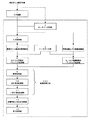
図1はこの実施の形態による点灯状態検出装置の全体構成を示すブロック図である。この点灯状態検出装置は、道路の照明設備のように、広域に多数設置された照明灯の点灯状態または不点灯状態を検出するものである。この装置では、人工衛星から地上を撮影した衛星写真または航空機から地上を撮影した航空写真を用いて、地上(例えば、高速道路として説明する)における照明灯の点灯状態を検知する。すなわち、近年、衛星写真や航空写真の高精細化が進み、衛星写真においても、2.5mの地上分解能(地上分解能とは画像中で識別できる地上の物理的な大きさの目安を表す)を有するものが実用化されている。本発明は、このような高精細写真情報を用いるものとする。 FIG. 1 is a block diagram showing the overall configuration of a lighting state detection apparatus according to this embodiment. This lighting state detection device detects lighting states or non-lighting states of a large number of illuminating lamps installed in a wide area, such as a road lighting facility. In this apparatus, a lighting state of an illumination lamp on the ground (for example, described as an expressway) is detected using a satellite photograph obtained by photographing the ground from an artificial satellite or an aerial photograph obtained by photographing the ground from an aircraft. In other words, in recent years, satellite photographs and aerial photographs have become more precise, and satellite photographs also have a ground resolution of 2.5 m (ground resolution represents a measure of the physical size of the ground that can be identified in an image). What you have has been put to practical use. The present invention uses such high-definition photographic information.
図1において、1は入力装置で、衛星写真または航空写真をオフラインで登録する場合に用いられる。すなわち、この入力装置1により、人工衛星または航空機から検出対象箇所を上空から撮影した写真情報を入力し、この写真情報を入力処理部3を介して衛星または航空写真格納部4(写真情報記憶手段の一例)に格納する。衛星写真または航空写真をオンラインで登録する場合はオンライン受信部2で受信し、入力処理部3を介して衛星または航空写真格納部4に格納する。
In FIG. 1,
5はGIS(Geographic Information System:地図情報システム)データ部で、地図情報を保持している。6はGIS情報と撮影された衛星写真または航空写真(以下、衛星写真として話を進める)による写真情報とをマッピングする第1のマッピング処理部である。この第1のマッピング処理部6は、検出対象箇所を上空から撮影した写真情報と、この写真情報に該当する地上部分の地図情報とを、縮尺及び緯度・経度を合わせて互いに合致させる。すなわち、この第1のマッピング処理部6は、衛星または航空写真格納部4に格納した写真情報とGISデータ部5のGIS情報との重ね合わせ処理を行う。
7は設備情報部(地図情報記憶手段の一例)で、照明設備などの設備情報、例えば、照明灯の設置場所が、緯度・経度情報により予め設定されている。8はGIS情報と設備情報部7に設定された照明灯の設置場所情報とをマッピングする第2のマッピング処理部である。この第2のマッピング処理部8は、検出対象となる地上部分の地図情報に、設備情報として予め設定された緯度・軽度情報に基づいて、照明灯の設置場所をマッピングする。すなわち、第2のマッピング処理部8は、照明灯の設置位置など、設備情報部7に格納した設備情報とGISデータ部5の地図情報との重ね合わせ処理を行う。
なお、上記設備情報には、照明灯の設置箇所とこの設置箇所に設置された照明灯との対応関係に加えて、各照明灯に電源を供給する器具(例えば、安定器など)の種類が、照明灯と対応させて設定されているものとする。 The facility information includes the type of appliance (for example, a ballast) that supplies power to each illumination light, in addition to the correspondence between the location of the illumination light and the illumination light installed at the installation location. Suppose that it is set in correspondence with the illumination lamp.
9は画像処理部、10は点灯検出処理部、11は不点灯検出処理部で、これらにより画像処理手段100が構成される。上記画像処理部9は、第1のマッピング処理部6で処理した画像情報と、第2のマッピング処理部8で処理した画像情報とを入力し、これら、すなわち、GIS情報、写真情報および設備情報を重ね合わせて画像処理する。点灯検出処理部10は、重ね合わされた画像情報から、点灯状態の照明灯を抽出し、どの照明灯が点灯しているかを検出する。不点灯検出処理部11は、重ね合わされた画像情報から、不点灯状態の照明灯を抽出し、どの照明灯が不点灯となっているかを検出する。
Reference numeral 9 denotes an image processing unit, 10 denotes a lighting detection processing unit, and 11 denotes a non-lighting detection processing unit. The image processing unit 9 inputs the image information processed by the first mapping processing unit 6 and the image information processed by the second mapping processing unit 8, that is, GIS information, photographic information, and facility information. And image processing. The lighting
すなわち、画像処理手段100は、衛星写真などの写真情報と、GISシステムによる地図情報と、照明灯の位置情報とを合致させ、写真情報上での照明灯の点灯状態または不点灯状態と、前記地図情報に設定された照明灯の位置とを対応させて、照明灯毎の点灯状態または不点灯状態を検出する。 That is, the image processing means 100 matches the photographic information such as satellite photographs, the map information by the GIS system, and the position information of the illuminating lamp, and the illuminating lamp lighting state or non-lighting state on the photographic information, The lighting state or the non-lighting state for each illumination light is detected in association with the position of the illumination light set in the map information.
12は設備交換手段として用いられる設備情報との比較処理部である。この比較処理部12は、照明灯の設置箇所と、この設置箇所に設置された照明灯の種類、或いは電源器具の種類とを対応させた設備情報を用い、不点灯と検出された照明灯の種類、或いはその照明等に対応する電源器具の種類を検出して、交換部材を容易に把握できるようにしている。
13は表示処理部で、点灯検出処理部10の結果と不点灯検出処理部11の結果、さらには、比較処理部12により設備情報との比較で得られる交換部材の情報を、それぞれ表示出力する。
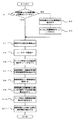
次に、動作説明を、図2のフローチャートを用いて行う。図2において、先ず、照明灯などの設備情報が登録されているか否かの判定を行う(S1)。設備情報としては、照明灯の緯度・経度情報、KP情報(キロポイントに関する情報‥道路(国道、県道、高速道路など)や河川などで、基準点(例えば国道であれば、国道の始まり)から何kmの地点であるかを示す情報)、上下線情報(上り線・下り線の情報)、照明器具種別および型番、設置年度、交換時期、予防交換予定時期、電源供給系統などの設備情報などである。設備情報が登録されていない場合は、照明設備などの設備情報登録を行い(S2)、GIS情報と設備情報とのマッピング処理を行う(S3)。 Next, the operation will be described using the flowchart of FIG. In FIG. 2, first, it is determined whether or not equipment information such as an illumination lamp is registered (S1). Equipment information includes latitude / longitude information of lighting, KP information (information about kilopoints ... roads (national roads, prefectural roads, highways, etc.), rivers, etc., from a reference point (for example, the start of a national road if it is a national road) Information indicating how many kilometers it is), vertical line information (upline / downline information), luminaire type and model number, installation year, replacement period, preventive replacement schedule, power supply system, etc. It is. If the facility information is not registered, the facility information such as the lighting facility is registered (S2), and the mapping process between the GIS information and the facility information is performed (S3).
設備情報が登録されている場合は、衛星写真または航空写真の取込を行う(S4)。次に、この取り込まれた写真情報の撮影対象部分に対応する地図情報(GISデータ)の読込みを行う(S5)。そして、これらGISデータと衛星写真または航空写真のマッピング処理を自動または手動で行う(S6)。また、設備情報から画像処理対象の照明灯の緯度・軽度情報を抽出しておく(S7)。 If the facility information is registered, the satellite photograph or the aerial photograph is taken in (S4). Next, the map information (GIS data) corresponding to the photographing target portion of the captured photo information is read (S5). Then, the mapping process between these GIS data and satellite photograph or aerial photograph is performed automatically or manually (S6). In addition, the latitude / lightness information of the illumination lamp targeted for image processing is extracted from the facility information (S7).
図3はこのマッピングイメージを表す図である。図3において、33は検出対象の道路を含む地上部分を撮影した衛星写真であり、例えば、2.5mの地上分解能を有する高精細のものとする。この衛星写真33においては、道路に沿って設けられた照明灯の個々について、点灯状態か不点灯状態かを識別することができる。図中、黒丸印は照明灯点灯箇所を表し、バツ印は照明灯不点灯箇所を表す。この写真情報は、図1における第1のマッピング処理部6により、該当する地図上にマッピングされる。 FIG. 3 is a diagram showing this mapping image. In FIG. 3, reference numeral 33 denotes a satellite photograph obtained by photographing a ground portion including a road to be detected, and is assumed to have a high definition having a ground resolution of 2.5 m, for example. In the satellite photograph 33, it is possible to identify whether each of the illuminating lamps provided along the road is in a lighting state or a non-lighting state. In the figure, black circles indicate lighting lamp lighting locations, and cross marks indicate lighting lamp non-lighting locations. This photographic information is mapped onto the corresponding map by the first mapping processing unit 6 in FIG.
31はGISシステムによる地図情報で、上記撮影部分に対応する領域の情報とする。32は照明設備などの設備情報で、各照明灯個々の位置が、緯度・経度情報として設定されている。この設備情報32と地図情報31とは図1における第2のマッピング処理部8でマッピング処理される。
このようにしてマッピングされた上述の各情報は、図1の画像処理部9で重ね合わされ、画像処理される。そして、この画像処理結果は図示しない記憶部に保持しておく(S8)。すなわち、前述のS7で設備情報から画像処理対象の緯度・経度情報を抽出し、S6のマッピングデータに対して抽出した緯度・経度情報の周辺箇所について画像処理(周辺との明暗比較など)し、処理結果を格納する。次に、この画像処理結果と設備情報32(照明灯の位置など)を比較処理し、点灯箇所と不点灯箇所を出力する(S9)。 The above-described information mapped in this manner is superimposed and processed by the image processing unit 9 in FIG. The image processing result is held in a storage unit (not shown) (S8). That is, the latitude / longitude information to be image-processed is extracted from the facility information in S7 described above, and image processing (such as comparison of brightness with the surroundings) is performed on the peripheral portions of the latitude / longitude information extracted for the mapping data in S6. Stores processing results. Next, the image processing result and the facility information 32 (illumination lamp position, etc.) are compared, and a lighting location and a non-lighting location are output (S9).
次に、照明灯の不点灯状態から、不点灯の原因がランプ切れか電源供給部の故障かの判定処理を行う(S10)。通常、照明灯の電源供給部は数十個の照明灯単位でグループ化されており、そのグループ全体のランプがすべて消灯している場合は、照明灯のランプ切れではなく電源供給部の故障と判定される。 Next, from the unlit state of the illuminating lamp, a determination process is performed to determine whether the cause of the unlit is a lamp burnout or a failure of the power supply unit (S10). Usually, the power supply unit of the illuminating lamp is grouped in units of several tens of illuminating lamps. If all the lamps of the entire group are turned off, it means that the failure of the power supply unit is not a lamp out of the illuminating lamp. Determined.
なお、照明灯が2個単位で不点灯の場合は、照明灯自体のランプ切れ或いは電源器具の故障のいずれかと判断される。通常、照明灯には放電等が用いられており、安定器などの電源器具が必要となる。この安定器などの電源器具は、経済性の上から、2つの照明灯に対して安定器1個の組み合わせで用いられる。この場合、安定器などの電源器具が故障すると、この電源器具に接続する2個の照明灯は不点灯となる。また、1個の照明灯がランプ切れによって不点灯になると、電源器具に対し2個の照明灯は直列接続されているため、もう一方の照明灯も不点灯となる。したがって、上述のように、照明灯が2個単位で不点灯の場合は、照明灯自体のランプ切れ或いは電源器具の故障のいずれかと判断される。 In addition, when the illuminating lamp is not turned on in units of two, it is determined that either the lamp of the illuminating lamp itself has run out or the power supply apparatus has failed. Usually, the discharge lamp etc. are used for the illuminating lamp, and a power supply device such as a ballast is required. This power supply device such as a ballast is used in combination with one ballast for two illumination lamps from the viewpoint of economy. In this case, when a power supply device such as a ballast breaks down, the two illumination lamps connected to the power supply device are not lit. Further, when one illuminating lamp is not lit due to lamp breakage, since the two illuminating lamps are connected in series to the power supply device, the other illuminating lamp is also unlit. Therefore, as described above, when the illumination lamps are not turned on in units of two, it is determined that either the lamp of the illumination lamp itself has run out or the power supply apparatus has failed.
すなわち、不点灯箇所及び不点灯個数から、不点灯の原因が、電源供給側の故障か、照明灯自体のランプ切れ或いは電源器具の故障かを判定できる。 That is, it can be determined from the non-lighting location and the number of non-lighting whether the cause of the non-lighting is a failure on the power supply side, a lamp failure of the illumination lamp itself, or a failure of the power supply apparatus.
このように不点灯の原因を判定した結果に応じて、電源供給部の故障の場合は、対応する交換部材などを持参して電源供給部に対する故障復旧作業を行い、照明灯自体、或いはその照明灯に対する安定器などの電源器具の故障の場合は、該当する交換部材を現地に携行して交換作業を実施する。この場合、設備情報から交換に必要な部材情報を抽出して対応する(S11)。例えば、抽出された交換部材を表示することにより、作業員は、現地に携行する交換部材を間違えることなく、適切に作業することができる。すなわち、不点灯となっている照明灯を特定できるので、特定された照明灯に対応する交換部材を設備情報から抽出して対応することができる。 Thus, in the case of a failure of the power supply unit according to the result of determining the cause of the non-lighting, bring the corresponding replacement member etc. to perform the failure recovery work for the power supply unit, and the illumination lamp itself or its illumination In the event of a failure of a power supply such as a ballast for the lamp, carry out the replacement work by bringing the relevant replacement member to the site. In this case, the member information necessary for the exchange is extracted from the facility information to cope with it (S11). For example, by displaying the extracted replacement member, the worker can appropriately work without making a mistake in the replacement member carried on site. That is, since the illuminating lamp that is not lit can be identified, the replacement member corresponding to the identified illuminating lamp can be extracted from the facility information and dealt with.
一般に、照明灯や安定器などの電源器具には、各メーカの製品が混在して使用されている場合が多く、互換性がないものもある。このような場合でも、設備情報として、前述のように、照明灯の設置箇所とこの設置箇所に設置された照明灯との対応関係、各照明灯に電源を供給する器具の種類、さらには電源供給部の構成用品が、それぞれ照明灯と対応させて設定されているので、不点灯箇所を特定することにより、適切な交換部材を抽出して対応することができる。 In general, power supply devices such as lighting lamps and ballasts are often used in a mixture of products from various manufacturers, and some of them are not compatible. Even in such a case, as described above, as the facility information, the correspondence between the installation location of the illumination lamp and the illumination lamp installed at this installation location, the type of appliance that supplies power to each illumination lamp, and the power supply Since the components of the supply unit are set so as to correspond to the illuminating lamps respectively, it is possible to extract and replace an appropriate replacement member by specifying a non-lighting location.
上記説明は、道路に沿って設けられる照明設備を対象として行ったが、このような道路事業者などが管理する照明灯のほかに、公園や河川などの照明灯についても同様に実施することができる。すなわち、公園や河川などの照明灯については、夜間に歩行など巡回車両以外の方法で確認する必要があったが、このような労力を要することなく、公園や河川など屋外に設置されている全ての照明灯の点灯状態または不点灯状態の検出に応用できる。 The above explanation was given for lighting equipment provided along the road, but in addition to the lighting lights managed by such road operators, etc., the lighting equipment such as parks and rivers can be implemented in the same way. it can. In other words, it was necessary to check the lighting of parks and rivers by means other than patrol vehicles such as walking at night, but without any labor, all installed outdoors such as parks and rivers. It can be applied to the detection of the lighting state or non-lighting state of the illumination lamp.
本発明によれば、照明灯が設置されている箇所に出向くことなくランプ切れを検出できるため省力化できる。照明灯にセンサ装置などを設置することがないため、イニシャルコトトとランニングコストを削減できる。巡回車両の低速走行によって発生していた交通渋滞の発生などを回避できる。電源供給部から複数の照明灯に電源供給されるため、電源供給部故障を照明灯のランプ切れと判断する場合があったが、ランプ切れと電源供給部故障を判別することも可能なため、適切な交換部材情報を提供することができ、交換作業開始後に交換部材の誤認識や欠品などが防止できる。 According to the present invention, since it is possible to detect a lamp break without going to a place where an illuminating lamp is installed, it is possible to save labor. Since there is no need to install a sensor device or the like on the illuminating lamp, the initial cost and running cost can be reduced. It is possible to avoid the occurrence of traffic congestion that has occurred due to low-speed traveling of patrol vehicles. Since power is supplied to a plurality of lighting lamps from the power supply unit, there was a case where it was determined that the power supply unit failure was out of the lamp of the lighting lamp, but it is also possible to determine lamp failure and power supply unit failure, Appropriate replacement member information can be provided, and erroneous recognition of the replacement member or missing parts can be prevented after the start of replacement work.
4 衛星または航空写真格納部
5 GISデータ(地図情報)部
7 設備情報部
6,8 マッピング処理部
100 画像処理手段
12 設備交換手段として機能する設備情報との比較処理部
31 GIS情報
32 設備情報
33 写真情報
4 Satellite or aerial
Claims (3)
前記照明灯の設置箇所について、緯度・経度情報により設定された検出対象箇所の地図情報を記憶した地図情報記憶手段と、
前記検出対象箇所を上空から撮影した写真情報を記憶した写真情報記憶手段と、
この写真情報記憶手段に記憶された写真情報と前記地図情報記憶手段に記憶された地図情報とを合致させ、前記写真情報における照明灯の点灯状態または不点灯状態と、前記地図情報に設定された照明灯の位置とを対応させて、前記照明灯毎の点灯状態または不点灯状態を検出する画像処理手段と、
を備えたことを特徴とする照明灯の点灯状態検出装置。 An illumination lamp lighting state detection device for detecting lighting or non-lighting of a plurality of illumination lamps installed in a wide area,
Map information storage means for storing the map information of the detection target location set by the latitude / longitude information for the installation location of the illumination light,
Photo information storage means for storing photo information obtained by photographing the detection target portion from above,
The photographic information stored in the photographic information storage means is matched with the map information stored in the map information storage means, and the lighting state or non-lighting state of the illumination lamp in the photographic information and the map information are set. Image processing means for detecting a lighting state or a non-lighting state for each of the lighting lamps in association with the position of the lighting lamp;
An illumination lamp lighting state detection device comprising:
Priority Applications (1)
| Application Number | Priority Date | Filing Date | Title |
|---|---|---|---|
| JP2006303974A JP4834516B2 (en) | 2006-11-09 | 2006-11-09 | Lighting lamp lighting state detection device |
Applications Claiming Priority (1)
| Application Number | Priority Date | Filing Date | Title |
|---|---|---|---|
| JP2006303974A JP4834516B2 (en) | 2006-11-09 | 2006-11-09 | Lighting lamp lighting state detection device |
Publications (2)
| Publication Number | Publication Date |
|---|---|
| JP2008123745A true JP2008123745A (en) | 2008-05-29 |
| JP4834516B2 JP4834516B2 (en) | 2011-12-14 |
Family
ID=39508295
Family Applications (1)
| Application Number | Title | Priority Date | Filing Date |
|---|---|---|---|
| JP2006303974A Expired - Fee Related JP4834516B2 (en) | 2006-11-09 | 2006-11-09 | Lighting lamp lighting state detection device |
Country Status (1)
| Country | Link |
|---|---|
| JP (1) | JP4834516B2 (en) |
Cited By (8)
| Publication number | Priority date | Publication date | Assignee | Title |
|---|---|---|---|---|
| US9082049B2 (en) | 2012-11-27 | 2015-07-14 | International Business Machines Corporation | Detecting broken lamps in a public lighting system via analyzation of satellite images |
| WO2016022020A1 (en) * | 2014-08-07 | 2016-02-11 | Mimos Berhad | System and method for detecting and reporting location of unilluminated streetlights |
| JP2016225067A (en) * | 2015-05-28 | 2016-12-28 | 株式会社石井幹子デザイン事務所 | Self-luminous lighting device, and landscape presentation system utilizing self-luminous lighting device |
| JP2017026412A (en) * | 2015-07-21 | 2017-02-02 | 株式会社トプコン | Lighting equipment management system |
| CN112949540A (en) * | 2021-03-16 | 2021-06-11 | 江苏海扬智慧物联研究院有限公司 | Street lamp state judgment method, device, equipment and medium based on satellite picture |
| JP2022521813A (en) * | 2019-03-18 | 2022-04-12 | シグニファイ ホールディング ビー ヴィ | Diagnosis of problems that occur when controlling lighting devices based on lighting device grouping information |
| CN115512229A (en) * | 2022-10-31 | 2022-12-23 | 智道网联科技(北京)有限公司 | Street lamp fault detection method and device, electronic equipment and storage medium |
| WO2025191632A1 (en) * | 2024-03-11 | 2025-09-18 | 日本電気株式会社 | Inspection support system, inspection support method, and recording medium |
Families Citing this family (2)
| Publication number | Priority date | Publication date | Assignee | Title |
|---|---|---|---|---|
| CN110708825A (en) * | 2019-08-23 | 2020-01-17 | 浙江亿科照明科技有限公司 | Intelligent lighting control method, node and system |
| US20230153392A1 (en) * | 2021-11-15 | 2023-05-18 | Signify Holding B.V. | Control device for predicting a data point from a predictor and a method thereof |
Citations (14)
| Publication number | Priority date | Publication date | Assignee | Title |
|---|---|---|---|---|
| JPH01296590A (en) * | 1988-05-25 | 1989-11-29 | Mirai Biru Kenkyu Kaihatsu Kk | Failure sensing device for lighting fixture |
| JPH0589972A (en) * | 1991-09-30 | 1993-04-09 | Toshiba Lighting & Technol Corp | Outdoor lighting fixture inspection system |
| JPH0963776A (en) * | 1995-08-21 | 1997-03-07 | Kensetsusho Kanto Chiho Kensetsu Kyokucho | Automatic blinker with illumination light defect detection device |
| JPH09128515A (en) * | 1995-10-26 | 1997-05-16 | Sumitomo Electric Ind Ltd | Disconnection detection device for aviation obstruction light |
| JP2000242796A (en) * | 1999-02-18 | 2000-09-08 | Ntt Data Corp | Method and apparatus for extracting change area in image data, recording medium |
| JP2001052882A (en) * | 1999-08-06 | 2001-02-23 | Toshiba Telecommunication System Engineering Corp | Lighting inspection system |
| JP2001085174A (en) * | 1999-09-20 | 2001-03-30 | Koito Ind Ltd | Method and apparatus for identifying pointless lighting |
| JP2004119030A (en) * | 2002-09-24 | 2004-04-15 | Shinkawa Denki:Kk | Street light management system |
| JP2004146281A (en) * | 2002-10-28 | 2004-05-20 | Matsushita Electric Works Ltd | Lighting lamp identification device |
| JP2005084332A (en) * | 2003-09-08 | 2005-03-31 | Denso Corp | Map display device and map display method |
| JP2005135834A (en) * | 2003-10-31 | 2005-05-26 | Mitsubishi Electric Corp | Lighting state monitoring method and lamp imaging device |
| JP2005283630A (en) * | 2004-03-26 | 2005-10-13 | Alpine Electronics Inc | Electronic apparatus having navigation function, and night scene map display method |
| JP2006065429A (en) * | 2004-08-25 | 2006-03-09 | Hitachi Software Eng Co Ltd | Device and method for extracting change of photographic image |
| JP2006228636A (en) * | 2005-02-18 | 2006-08-31 | Toshiba Corp | Lighting lamp deterioration detector |
-
2006
- 2006-11-09 JP JP2006303974A patent/JP4834516B2/en not_active Expired - Fee Related
Patent Citations (14)
| Publication number | Priority date | Publication date | Assignee | Title |
|---|---|---|---|---|
| JPH01296590A (en) * | 1988-05-25 | 1989-11-29 | Mirai Biru Kenkyu Kaihatsu Kk | Failure sensing device for lighting fixture |
| JPH0589972A (en) * | 1991-09-30 | 1993-04-09 | Toshiba Lighting & Technol Corp | Outdoor lighting fixture inspection system |
| JPH0963776A (en) * | 1995-08-21 | 1997-03-07 | Kensetsusho Kanto Chiho Kensetsu Kyokucho | Automatic blinker with illumination light defect detection device |
| JPH09128515A (en) * | 1995-10-26 | 1997-05-16 | Sumitomo Electric Ind Ltd | Disconnection detection device for aviation obstruction light |
| JP2000242796A (en) * | 1999-02-18 | 2000-09-08 | Ntt Data Corp | Method and apparatus for extracting change area in image data, recording medium |
| JP2001052882A (en) * | 1999-08-06 | 2001-02-23 | Toshiba Telecommunication System Engineering Corp | Lighting inspection system |
| JP2001085174A (en) * | 1999-09-20 | 2001-03-30 | Koito Ind Ltd | Method and apparatus for identifying pointless lighting |
| JP2004119030A (en) * | 2002-09-24 | 2004-04-15 | Shinkawa Denki:Kk | Street light management system |
| JP2004146281A (en) * | 2002-10-28 | 2004-05-20 | Matsushita Electric Works Ltd | Lighting lamp identification device |
| JP2005084332A (en) * | 2003-09-08 | 2005-03-31 | Denso Corp | Map display device and map display method |
| JP2005135834A (en) * | 2003-10-31 | 2005-05-26 | Mitsubishi Electric Corp | Lighting state monitoring method and lamp imaging device |
| JP2005283630A (en) * | 2004-03-26 | 2005-10-13 | Alpine Electronics Inc | Electronic apparatus having navigation function, and night scene map display method |
| JP2006065429A (en) * | 2004-08-25 | 2006-03-09 | Hitachi Software Eng Co Ltd | Device and method for extracting change of photographic image |
| JP2006228636A (en) * | 2005-02-18 | 2006-08-31 | Toshiba Corp | Lighting lamp deterioration detector |
Cited By (10)
| Publication number | Priority date | Publication date | Assignee | Title |
|---|---|---|---|---|
| US9082049B2 (en) | 2012-11-27 | 2015-07-14 | International Business Machines Corporation | Detecting broken lamps in a public lighting system via analyzation of satellite images |
| WO2016022020A1 (en) * | 2014-08-07 | 2016-02-11 | Mimos Berhad | System and method for detecting and reporting location of unilluminated streetlights |
| JP2016225067A (en) * | 2015-05-28 | 2016-12-28 | 株式会社石井幹子デザイン事務所 | Self-luminous lighting device, and landscape presentation system utilizing self-luminous lighting device |
| JP2017026412A (en) * | 2015-07-21 | 2017-02-02 | 株式会社トプコン | Lighting equipment management system |
| JP2022521813A (en) * | 2019-03-18 | 2022-04-12 | シグニファイ ホールディング ビー ヴィ | Diagnosis of problems that occur when controlling lighting devices based on lighting device grouping information |
| JP7143537B2 (en) | 2019-03-18 | 2022-09-28 | シグニファイ ホールディング ビー ヴィ | Diagnose problems encountered when controlling lighting devices based on lighting device grouping information |
| US11937356B2 (en) | 2019-03-18 | 2024-03-19 | Signify Holding B.V. | Diagnosing a problem occurring when controlling a lighting device based on lighting device grouping information |
| CN112949540A (en) * | 2021-03-16 | 2021-06-11 | 江苏海扬智慧物联研究院有限公司 | Street lamp state judgment method, device, equipment and medium based on satellite picture |
| CN115512229A (en) * | 2022-10-31 | 2022-12-23 | 智道网联科技(北京)有限公司 | Street lamp fault detection method and device, electronic equipment and storage medium |
| WO2025191632A1 (en) * | 2024-03-11 | 2025-09-18 | 日本電気株式会社 | Inspection support system, inspection support method, and recording medium |
Also Published As
| Publication number | Publication date |
|---|---|
| JP4834516B2 (en) | 2011-12-14 |
Similar Documents
| Publication | Publication Date | Title |
|---|---|---|
| JP4582192B2 (en) | Vehicle failure analysis system, vehicle failure analysis device, vehicle failure analysis method | |
| KR102503572B1 (en) | Automated Performance Tests for Autonomous Vehicles | |
| JP4834516B2 (en) | Lighting lamp lighting state detection device | |
| US11963066B2 (en) | Method for indicating parking position and vehicle-mounted device | |
| JP6527772B2 (en) | Spatial light measurement method and spatial light measurement system | |
| US9952091B2 (en) | Management system for illumination facility | |
| US20210086811A1 (en) | Railroad crossing gate light out detector apparatus and method | |
| CA2759900A1 (en) | Advertisement display system | |
| WO2014097029A1 (en) | Monitoring of operational status of street devices | |
| CN109448406B (en) | Traffic synchronous indicating system and vehicle-mounted prompting terminal with indicating program | |
| KR101892529B1 (en) | Apparatus for recognizing absolute position using marker recognition on a road and method therefor | |
| KR20230059290A (en) | Apparatus for detecting a failure of street light using a sensor | |
| KR101492578B1 (en) | Monitoring and Control System for the road sign and the traffic safety sign | |
| JP7444148B2 (en) | Information processing device, information processing method, program | |
| JP2009129290A (en) | Traffic signal detection apparatus, traffic signal detection method and program | |
| EP1719091B1 (en) | Method and system for verifying a traffic violation image | |
| CN115294446A (en) | A remote street lamp fault monitoring and indication system | |
| CN208400322U (en) | Heavenly Stems and Earthly Branches road safety early warning system | |
| JP2023117185A (en) | System and program etc. | |
| JP3764306B2 (en) | Spotlight illumination identification method and apparatus | |
| JP2005135834A (en) | Lighting state monitoring method and lamp imaging device | |
| KR101701788B1 (en) | Apparatus for collecting a defect equipment information and circumference environment information | |
| CN111845594B (en) | Automobile fault processing method and device | |
| KR101277829B1 (en) | Apparatus for control crosswalk lighting using switch of traffic signal controller | |
| CN117035748B (en) | Subway station lamp overhaul auxiliary system and method |
Legal Events
| Date | Code | Title | Description |
|---|---|---|---|
| A621 | Written request for application examination |
Free format text: JAPANESE INTERMEDIATE CODE: A621 Effective date: 20090907 |
|
| A977 | Report on retrieval |
Free format text: JAPANESE INTERMEDIATE CODE: A971007 Effective date: 20110818 |
|
| TRDD | Decision of grant or rejection written | ||
| A01 | Written decision to grant a patent or to grant a registration (utility model) |
Free format text: JAPANESE INTERMEDIATE CODE: A01 Effective date: 20110830 |
|
| A01 | Written decision to grant a patent or to grant a registration (utility model) |
Free format text: JAPANESE INTERMEDIATE CODE: A01 |
|
| A61 | First payment of annual fees (during grant procedure) |
Free format text: JAPANESE INTERMEDIATE CODE: A61 Effective date: 20110926 |
|
| R150 | Certificate of patent or registration of utility model |
Ref document number: 4834516 Country of ref document: JP Free format text: JAPANESE INTERMEDIATE CODE: R150 Free format text: JAPANESE INTERMEDIATE CODE: R150 |
|
| FPAY | Renewal fee payment (event date is renewal date of database) |
Free format text: PAYMENT UNTIL: 20140930 Year of fee payment: 3 |
|
| S531 | Written request for registration of change of domicile |
Free format text: JAPANESE INTERMEDIATE CODE: R313531 |
|
| R350 | Written notification of registration of transfer |
Free format text: JAPANESE INTERMEDIATE CODE: R350 |
|
| S533 | Written request for registration of change of name |
Free format text: JAPANESE INTERMEDIATE CODE: R313533 |
|
| R350 | Written notification of registration of transfer |
Free format text: JAPANESE INTERMEDIATE CODE: R350 |
|
| LAPS | Cancellation because of no payment of annual fees |