JP2008140077A - 球体の絶対角度検出システム、球体アクチュエータおよびポインティングデバイス - Google Patents
球体の絶対角度検出システム、球体アクチュエータおよびポインティングデバイス Download PDFInfo
- Publication number
- JP2008140077A JP2008140077A JP2006325009A JP2006325009A JP2008140077A JP 2008140077 A JP2008140077 A JP 2008140077A JP 2006325009 A JP2006325009 A JP 2006325009A JP 2006325009 A JP2006325009 A JP 2006325009A JP 2008140077 A JP2008140077 A JP 2008140077A
- Authority
- JP
- Japan
- Prior art keywords
- sphere
- image recognition
- absolute angle
- image
- pattern
- Prior art date
- Legal status (The legal status is an assumption and is not a legal conclusion. Google has not performed a legal analysis and makes no representation as to the accuracy of the status listed.)
- Pending
Links
Images


Classifications
-
- G—PHYSICS
- G01—MEASURING; TESTING
- G01D—MEASURING NOT SPECIALLY ADAPTED FOR A SPECIFIC VARIABLE; ARRANGEMENTS FOR MEASURING TWO OR MORE VARIABLES NOT COVERED IN A SINGLE OTHER SUBCLASS; TARIFF METERING APPARATUS; MEASURING OR TESTING NOT OTHERWISE PROVIDED FOR
- G01D5/00—Mechanical means for transferring the output of a sensing member; Means for converting the output of a sensing member to another variable where the form or nature of the sensing member does not constrain the means for converting; Transducers not specially adapted for a specific variable
- G01D5/26—Mechanical means for transferring the output of a sensing member; Means for converting the output of a sensing member to another variable where the form or nature of the sensing member does not constrain the means for converting; Transducers not specially adapted for a specific variable characterised by optical transfer means, i.e. using infrared, visible, or ultraviolet light
- G01D5/28—Mechanical means for transferring the output of a sensing member; Means for converting the output of a sensing member to another variable where the form or nature of the sensing member does not constrain the means for converting; Transducers not specially adapted for a specific variable characterised by optical transfer means, i.e. using infrared, visible, or ultraviolet light with deflection of beams of light, e.g. for direct optical indication
-
- G—PHYSICS
- G06—COMPUTING OR CALCULATING; COUNTING
- G06F—ELECTRIC DIGITAL DATA PROCESSING
- G06F3/00—Input arrangements for transferring data to be processed into a form capable of being handled by the computer; Output arrangements for transferring data from processing unit to output unit, e.g. interface arrangements
- G06F3/01—Input arrangements or combined input and output arrangements for interaction between user and computer
- G06F3/03—Arrangements for converting the position or the displacement of a member into a coded form
- G06F3/0304—Detection arrangements using opto-electronic means
- G06F3/0317—Detection arrangements using opto-electronic means in co-operation with a patterned surface, e.g. absolute position or relative movement detection for an optical mouse or pen positioned with respect to a coded surface
- G06F3/0321—Detection arrangements using opto-electronic means in co-operation with a patterned surface, e.g. absolute position or relative movement detection for an optical mouse or pen positioned with respect to a coded surface by optically sensing the absolute position with respect to a regularly patterned surface forming a passive digitiser, e.g. pen optically detecting position indicative tags printed on a paper sheet
-
- G—PHYSICS
- G06—COMPUTING OR CALCULATING; COUNTING
- G06F—ELECTRIC DIGITAL DATA PROCESSING
- G06F3/00—Input arrangements for transferring data to be processed into a form capable of being handled by the computer; Output arrangements for transferring data from processing unit to output unit, e.g. interface arrangements
- G06F3/01—Input arrangements or combined input and output arrangements for interaction between user and computer
- G06F3/03—Arrangements for converting the position or the displacement of a member into a coded form
- G06F3/033—Pointing devices displaced or positioned by the user, e.g. mice, trackballs, pens or joysticks; Accessories therefor
- G06F3/0338—Pointing devices displaced or positioned by the user, e.g. mice, trackballs, pens or joysticks; Accessories therefor with detection of limited linear or angular displacement of an operating part of the device from a neutral position, e.g. isotonic or isometric joysticks
Landscapes
- Engineering & Computer Science (AREA)
- General Engineering & Computer Science (AREA)
- Theoretical Computer Science (AREA)
- Physics & Mathematics (AREA)
- General Physics & Mathematics (AREA)
- Human Computer Interaction (AREA)
- Position Input By Displaying (AREA)
- Length Measuring Devices By Optical Means (AREA)
- Optical Transform (AREA)
Abstract
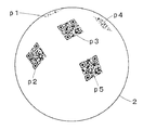
【解決手段】 球体の絶対角度検出システム1は、球体2の絶対角度検出のための、面状の画像認識用パターンPが設けられた球体2と、球体2の外部に設けられた画像認識装置3とから構成される。画像認識用パターンPは、QRコード(登録商標)などを要素パターンp1等として球体2の表面上に複数配置して構成することができる。画像認識装置3は、画像入力部4と入力画像処理部5からなり、得られた画像情報から球体2の絶対角度情報が出力される。
【選択図】 図1
Description
(2) 前記画像認識用パターンは、球心まわりの自由回転により前記球体外の一定点から視認される形状が変化するものであることを特徴とする、(1)に記載の球体の絶対角度検出システム。
(3) 前記画像認識用パターンは、前記球体の球面上または内部において、相互に異なる位置に設けられた複数の要素パターンからなることを特徴とする、(2)に記載の球体の絶対角度検出システム。
(4) 前記画像認識用パターンの要素パターンには、QRコード(登録商標)または2次元もしくは1次元のバーコードの少なくともいずれかが用いられることを特徴とする、(3)に記載の球体の絶対角度検出システム。
(5) 球体の絶対角度検出のための面状もしくは立体形状の画像認識用パターンが設けられている球体アクチュエータであって、画像として入力された該画像認識用パターンを処理して該球体の角度情報を得るために外部に画像認識装置を備えていることを特徴とする、球体アクチュエータ。
(6) 球体の絶対角度検出のための面状もしくは立体形状の画像認識用パターンが設けられた入力操作用の球体と、画像として入力された該画像認識用パターンを処理して該球体の角度情報を得るための、該球体の外部に設けられた画像認識装置とを備えてなることを特徴とする、ポインティングデバイス。
図1は、本発明の球体の絶対角度検出システムの実施例を示す説明図である。また、
図2Aは、図1に示す実施例に係る球体の底面図、
図2Bは、図1に示す実施例に係る球体の一斜視図である。これらに例示されるように、本発明の球体の絶対角度検出システム1は、球体2の絶対角度検出のための、面状の画像認識用パターンPが設けられた球体2と、球体2の外部に設けられた画像認識装置3とから、主として構成される。符号6で示される要素は、球体2との間において回転運動を伝動、媒介するための伝動部である。
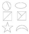
図3(b)は、本発明システムの画像認識用パターンとして適性の低い画像の一例として、簡単な平面幾何学図形からなるものを示す平面図である。これらに示すように、簡単な形状の幾何学図形であっても、図3(b)のような極めて簡単な構成でない限り、そのほとんどを本発明に係る画像認識用パターンとして用いることができる。
2…球体
3…画像認識装置
4…画像入力部
5…入力画像処理部
6…伝動部
P…画像認識用パターン
p1、p2、p3、p4、p5…要素パターン
Claims (6)
- 球体の絶対角度検出のための面状もしくは立体形状の画像認識用パターンが設けられた球体と、入力された該画像認識用パターン画像を処理して該球体の角度情報を得るための、該球体の外部に設けられた画像認識装置とからなる、球体の絶対角度検出システム。
- 前記画像認識用パターンは、球心まわりの自由回転により前記球体外の一定点から視認される形状が変化するものであることを特徴とする、請求項1に記載の球体の絶対角度検出システム。
- 前記画像認識用パターンは、前記球体の球面上または内部において、相互に異なる位置に設けられた複数の要素パターンからなることを特徴とする、請求項2に記載の球体の絶対角度検出システム。
- 前記画像認識用パターンの要素パターンには、QRコード(登録商標)または2次元もしくは1次元のバーコードの少なくともいずれかが用いられることを特徴とする、請求項3に記載の球体の絶対角度検出システム。
- 球体の絶対角度検出のための面状もしくは立体形状の画像認識用パターンが設けられている球体アクチュエータであって、画像として入力された該画像認識用パターンを処理して該球体の角度情報を得るために外部に画像認識装置を備えていることを特徴とする、球体アクチュエータ。
- 球体の絶対角度検出のための面状もしくは立体形状の画像認識用パターンが設けられた入力操作用の球体と、画像として入力された該画像認識用パターンを処理して該球体の角度情報を得るための、該球体の外部に設けられた画像認識装置とを備えてなることを特徴とする、ポインティングデバイス。
Priority Applications (5)
| Application Number | Priority Date | Filing Date | Title |
|---|---|---|---|
| JP2006325009A JP2008140077A (ja) | 2006-11-30 | 2006-11-30 | 球体の絶対角度検出システム、球体アクチュエータおよびポインティングデバイス |
| PCT/JP2007/073012 WO2008069084A1 (ja) | 2006-11-30 | 2007-11-29 | 球体の絶対角度検出システム、球体アクチュエータおよびポインティングデバイス |
| EP07832727A EP2093648A1 (en) | 2006-11-30 | 2007-11-29 | Sphere absolute angle detection system, sphere actuator, and pointing device |
| CNA2007800435410A CN101553772A (zh) | 2006-11-30 | 2007-11-29 | 球体绝对角度检测系统、球体致动器以及指示装置 |
| US12/513,546 US20090303181A1 (en) | 2006-11-30 | 2007-11-29 | Sphere absolute angle detection system, sphere actuator, and pointing device |
Applications Claiming Priority (1)
| Application Number | Priority Date | Filing Date | Title |
|---|---|---|---|
| JP2006325009A JP2008140077A (ja) | 2006-11-30 | 2006-11-30 | 球体の絶対角度検出システム、球体アクチュエータおよびポインティングデバイス |
Publications (1)
| Publication Number | Publication Date |
|---|---|
| JP2008140077A true JP2008140077A (ja) | 2008-06-19 |
Family
ID=39491983
Family Applications (1)
| Application Number | Title | Priority Date | Filing Date |
|---|---|---|---|
| JP2006325009A Pending JP2008140077A (ja) | 2006-11-30 | 2006-11-30 | 球体の絶対角度検出システム、球体アクチュエータおよびポインティングデバイス |
Country Status (5)
| Country | Link |
|---|---|
| US (1) | US20090303181A1 (ja) |
| EP (1) | EP2093648A1 (ja) |
| JP (1) | JP2008140077A (ja) |
| CN (1) | CN101553772A (ja) |
| WO (1) | WO2008069084A1 (ja) |
Cited By (6)
| Publication number | Priority date | Publication date | Assignee | Title |
|---|---|---|---|---|
| JP2010140386A (ja) * | 2008-12-15 | 2010-06-24 | Panasonic Corp | 光学式角度センサ |
| JP2012037326A (ja) * | 2010-08-05 | 2012-02-23 | Jtekt Corp | 楕円球体の挙動解析方法 |
| JP2014178141A (ja) * | 2013-03-13 | 2014-09-25 | Kagoshima Univ | キャリブレーションシステム、およびキャリブレーション方法 |
| JP2016102682A (ja) * | 2014-11-27 | 2016-06-02 | 株式会社トプコン | 傾斜検出装置及び回転レーザ装置 |
| JP2017091050A (ja) * | 2015-11-05 | 2017-05-25 | 株式会社オプティム | 立体型情報コード、及び、立体型情報コード読み取り装置 |
| JP2019039926A (ja) * | 2018-09-26 | 2019-03-14 | 株式会社トプコン | 傾斜検出装置及び回転レーザ装置 |
Families Citing this family (3)
| Publication number | Priority date | Publication date | Assignee | Title |
|---|---|---|---|---|
| DE102010052678A1 (de) * | 2010-11-24 | 2012-05-24 | Aap Implantate Ag | Koordinatenmess- und Positioniersystem |
| CN111488869B (zh) * | 2020-06-08 | 2024-09-17 | 丝路视觉科技股份有限公司 | 一种互动装置 |
| CN114371740B (zh) * | 2021-11-24 | 2024-03-22 | 北京特种机械研究所 | 球形姿态控制方法、装置、设备及计算机可读存储介质 |
Citations (5)
| Publication number | Priority date | Publication date | Assignee | Title |
|---|---|---|---|---|
| JP2002005620A (ja) * | 2000-06-27 | 2002-01-09 | Seiko Epson Corp | 位置検出方法および位置検出機構 |
| JP2002081925A (ja) * | 2000-09-06 | 2002-03-22 | Seiko Epson Corp | 球体の位相の駆動装置、位相の検出方法、ならびに、情報記録媒体 |
| JP2003014459A (ja) * | 2001-07-03 | 2003-01-15 | Sony Corp | 方位検出装置、方位検出方法、歩行検出装置 |
| JP2004015965A (ja) * | 2002-06-10 | 2004-01-15 | Ricoh Co Ltd | 球面モータ |
| JP2005055177A (ja) * | 2002-01-18 | 2005-03-03 | Nippon Telegr & Teleph Corp <Ntt> | 3次元位置・姿勢検出用立体、3次元位置・姿勢検出方法、3次元位置・姿勢検出装置、3次元位置・姿勢検出プログラム、および該プログラムを記録した記録媒体 |
Family Cites Families (9)
| Publication number | Priority date | Publication date | Assignee | Title |
|---|---|---|---|---|
| KR940022342A (ko) * | 1993-03-19 | 1994-10-20 | 탁승호 | 컴팩트 마우스 구조체 |
| JPH0791941A (ja) * | 1993-09-24 | 1995-04-07 | Nikon Corp | 回転角検出装置 |
| US6172665B1 (en) * | 1994-11-14 | 2001-01-09 | Edward T. Bullister | Mouse and trackball with optimal measurement optics |
| EP0992936A3 (en) * | 1998-10-06 | 2003-01-02 | Agilent Technologies, Inc. (a Delaware corporation) | Optical computer pointing device |
| US7032469B2 (en) * | 2002-11-12 | 2006-04-25 | Raytheon Company | Three axes line-of-sight transducer |
| JP2004246648A (ja) | 2003-02-14 | 2004-09-02 | Tamagawa Seiki Co Ltd | 意匠入りトラックボール |
| JP4876233B2 (ja) | 2004-03-22 | 2012-02-15 | 多摩川精機株式会社 | 位置検出器および被検出体 |
| US7340344B2 (en) * | 2004-09-10 | 2008-03-04 | Honeywell International Inc. | Spherical position monitoring system |
| US7295947B2 (en) * | 2004-09-10 | 2007-11-13 | Honeywell International Inc. | Absolute position determination of an object using pattern recognition |
-
2006
- 2006-11-30 JP JP2006325009A patent/JP2008140077A/ja active Pending
-
2007
- 2007-11-29 US US12/513,546 patent/US20090303181A1/en not_active Abandoned
- 2007-11-29 WO PCT/JP2007/073012 patent/WO2008069084A1/ja not_active Ceased
- 2007-11-29 CN CNA2007800435410A patent/CN101553772A/zh active Pending
- 2007-11-29 EP EP07832727A patent/EP2093648A1/en not_active Withdrawn
Patent Citations (5)
| Publication number | Priority date | Publication date | Assignee | Title |
|---|---|---|---|---|
| JP2002005620A (ja) * | 2000-06-27 | 2002-01-09 | Seiko Epson Corp | 位置検出方法および位置検出機構 |
| JP2002081925A (ja) * | 2000-09-06 | 2002-03-22 | Seiko Epson Corp | 球体の位相の駆動装置、位相の検出方法、ならびに、情報記録媒体 |
| JP2003014459A (ja) * | 2001-07-03 | 2003-01-15 | Sony Corp | 方位検出装置、方位検出方法、歩行検出装置 |
| JP2005055177A (ja) * | 2002-01-18 | 2005-03-03 | Nippon Telegr & Teleph Corp <Ntt> | 3次元位置・姿勢検出用立体、3次元位置・姿勢検出方法、3次元位置・姿勢検出装置、3次元位置・姿勢検出プログラム、および該プログラムを記録した記録媒体 |
| JP2004015965A (ja) * | 2002-06-10 | 2004-01-15 | Ricoh Co Ltd | 球面モータ |
Cited By (6)
| Publication number | Priority date | Publication date | Assignee | Title |
|---|---|---|---|---|
| JP2010140386A (ja) * | 2008-12-15 | 2010-06-24 | Panasonic Corp | 光学式角度センサ |
| JP2012037326A (ja) * | 2010-08-05 | 2012-02-23 | Jtekt Corp | 楕円球体の挙動解析方法 |
| JP2014178141A (ja) * | 2013-03-13 | 2014-09-25 | Kagoshima Univ | キャリブレーションシステム、およびキャリブレーション方法 |
| JP2016102682A (ja) * | 2014-11-27 | 2016-06-02 | 株式会社トプコン | 傾斜検出装置及び回転レーザ装置 |
| JP2017091050A (ja) * | 2015-11-05 | 2017-05-25 | 株式会社オプティム | 立体型情報コード、及び、立体型情報コード読み取り装置 |
| JP2019039926A (ja) * | 2018-09-26 | 2019-03-14 | 株式会社トプコン | 傾斜検出装置及び回転レーザ装置 |
Also Published As
| Publication number | Publication date |
|---|---|
| CN101553772A (zh) | 2009-10-07 |
| US20090303181A1 (en) | 2009-12-10 |
| EP2093648A1 (en) | 2009-08-26 |
| WO2008069084A1 (ja) | 2008-06-12 |
Similar Documents
| Publication | Publication Date | Title |
|---|---|---|
| WO2008069084A1 (ja) | 球体の絶対角度検出システム、球体アクチュエータおよびポインティングデバイス | |
| Nguyen et al. | Capturing natural-colour 3D models of insects for species discovery and diagnostics | |
| TWI443587B (zh) | 三維雙模掃描裝置及三維雙模掃描系統 | |
| Pérez et al. | Robot guidance using machine vision techniques in industrial environments: A comparative review | |
| US9432655B2 (en) | Three-dimensional scanner based on contours from shadow images | |
| US20130106833A1 (en) | Method and apparatus for optical tracking of 3d pose using complex markers | |
| Abraham et al. | Hand tracking and gesture recognition using lensless smart sensors | |
| JP6889865B2 (ja) | テンプレート作成装置、物体認識処理装置、テンプレート作成方法及びプログラム | |
| Villena-Martínez et al. | A quantitative comparison of calibration methods for RGB-D sensors using different technologies | |
| Stancic et al. | Design, development and evaluation of optical motion‐tracking system based on active white light markers | |
| Chen et al. | Robust computer vision chess analysis and interaction with a humanoid robot | |
| US20160171702A1 (en) | Optical tracking | |
| Gomes et al. | Blocks world of touch: Exploiting the advantages of all-around finger sensing in robot grasping | |
| Agostinelli et al. | Preliminary validation of a low-cost motion analysis system based on RGB cameras to support the evaluation of postural risk assessment | |
| Aalerud et al. | Automatic calibration of an industrial RGB-D camera network using retroreflective fiducial markers | |
| García-Ruiz et al. | Fiducial objects: Custom design and evaluation | |
| Chiang et al. | Development of a stereo vision measurement system for a 3D three-axial pneumatic parallel mechanism robot arm | |
| Bošnak et al. | Fast and reliable alternative to encoder-based measurements of multiple 2-DOF rotary-linear transformable objects using a network of image sensors with application to table football | |
| US20200346103A1 (en) | Tracking three dimensional puzzle components using embedded image sensors and contactless absolute position encoders | |
| Pecheux et al. | Self calibration of a sonar–vision system for underwater vehicles: A new method and a dataset | |
| Ramasubramanian et al. | On the evaluation of diverse vision systems towards detecting human pose in collaborative robot applications | |
| Le et al. | A PCB alignment system using RST template matching with CUDA on embedded GPU board | |
| Gomes et al. | Geltip tactile sensor for dexterous manipulation in clutter | |
| Veinidis et al. | 3D reconstruction of fishes using coded structured light | |
| Balasubramanian et al. | Vision-based 6D pose analytics solution for high-precision industrial robot pick-and-place applications |
Legal Events
| Date | Code | Title | Description |
|---|---|---|---|
| A621 | Written request for application examination |
Free format text: JAPANESE INTERMEDIATE CODE: A621 Effective date: 20091130 |
|
| A131 | Notification of reasons for refusal |
Free format text: JAPANESE INTERMEDIATE CODE: A131 Effective date: 20111003 |
|
| A521 | Request for written amendment filed |
Free format text: JAPANESE INTERMEDIATE CODE: A523 Effective date: 20111201 |
|
| A131 | Notification of reasons for refusal |
Free format text: JAPANESE INTERMEDIATE CODE: A131 Effective date: 20120824 |
|
| A02 | Decision of refusal |
Free format text: JAPANESE INTERMEDIATE CODE: A02 Effective date: 20121226 |