JP2008182103A - Airtight sealed package - Google Patents
Airtight sealed package Download PDFInfo
- Publication number
- JP2008182103A JP2008182103A JP2007015152A JP2007015152A JP2008182103A JP 2008182103 A JP2008182103 A JP 2008182103A JP 2007015152 A JP2007015152 A JP 2007015152A JP 2007015152 A JP2007015152 A JP 2007015152A JP 2008182103 A JP2008182103 A JP 2008182103A
- Authority
- JP
- Japan
- Prior art keywords
- gas
- energy
- pressure
- package according
- hermetically sealed
- Prior art date
- Legal status (The legal status is an assumption and is not a legal conclusion. Google has not performed a legal analysis and makes no representation as to the accuracy of the status listed.)
- Withdrawn
Links
Images



Classifications
-
- H—ELECTRICITY
- H10—SEMICONDUCTOR DEVICES; ELECTRIC SOLID-STATE DEVICES NOT OTHERWISE PROVIDED FOR
- H10W—GENERIC PACKAGES, INTERCONNECTIONS, CONNECTORS OR OTHER CONSTRUCTIONAL DETAILS OF DEVICES COVERED BY CLASS H10
- H10W76/00—Containers; Fillings or auxiliary members therefor; Seals
- H10W76/40—Fillings or auxiliary members in containers, e.g. centering rings
- H10W76/42—Fillings
- H10W76/48—Fillings including materials for absorbing or reacting with moisture or other undesired substances
-
- B—PERFORMING OPERATIONS; TRANSPORTING
- B81—MICROSTRUCTURAL TECHNOLOGY
- B81B—MICROSTRUCTURAL DEVICES OR SYSTEMS, e.g. MICROMECHANICAL DEVICES
- B81B7/00—Microstructural systems ; Auxiliary parts of microstructural devices or systems
- B81B7/0032—Packages or encapsulation
- B81B7/0035—Packages or encapsulation for maintaining a controlled atmosphere inside of the chamber containing the MEMS
- B81B7/0038—Packages or encapsulation for maintaining a controlled atmosphere inside of the chamber containing the MEMS using materials for controlling the level of pressure, contaminants or moisture inside of the package, e.g. getters
-
- B—PERFORMING OPERATIONS; TRANSPORTING
- B81—MICROSTRUCTURAL TECHNOLOGY
- B81C—PROCESSES OR APPARATUS SPECIALLY ADAPTED FOR THE MANUFACTURE OR TREATMENT OF MICROSTRUCTURAL DEVICES OR SYSTEMS
- B81C1/00—Manufacture or treatment of devices or systems in or on a substrate
- B81C1/00015—Manufacture or treatment of devices or systems in or on a substrate for manufacturing microsystems
- B81C1/00261—Processes for packaging MEMS devices
- B81C1/00277—Processes for packaging MEMS devices for maintaining a controlled atmosphere inside of the cavity containing the MEMS
- B81C1/00285—Processes for packaging MEMS devices for maintaining a controlled atmosphere inside of the cavity containing the MEMS using materials for controlling the level of pressure, contaminants or moisture inside of the package, e.g. getters
-
- H—ELECTRICITY
- H10—SEMICONDUCTOR DEVICES; ELECTRIC SOLID-STATE DEVICES NOT OTHERWISE PROVIDED FOR
- H10W—GENERIC PACKAGES, INTERCONNECTIONS, CONNECTORS OR OTHER CONSTRUCTIONAL DETAILS OF DEVICES COVERED BY CLASS H10
- H10W76/00—Containers; Fillings or auxiliary members therefor; Seals
- H10W76/10—Containers or parts thereof
- H10W76/12—Containers or parts thereof characterised by their shape
Landscapes
- Engineering & Computer Science (AREA)
- Microelectronics & Electronic Packaging (AREA)
- Manufacturing & Machinery (AREA)
- Computer Hardware Design (AREA)
- Micromachines (AREA)
- Mechanical Light Control Or Optical Switches (AREA)
Abstract
【課題】不活性ガスを使用しなくても真空度調整が可能な気密封止パッケージを提供すること。
【解決手段】蓋9とパッケージ基板5の少なくとも何れか一方に、気密封止パッケージ内にMEMSデバイス1を気密封止された状態で外部からのエネルギーを受けて内部封止空間12内の真空度を調整する圧力調整部材13を設ける。この圧力調整部材13に光学窓10を介して外部からエネルギーを加えることにより、内部封止空間12内の真空度が調整される。
【選択図】図1An airtight sealed package capable of adjusting the degree of vacuum without using an inert gas.
A degree of vacuum in an internal sealing space is received by energy from the outside in a state in which a MEMS device is hermetically sealed in at least one of a lid and a package substrate. A pressure adjusting member 13 for adjusting the pressure is provided. By applying energy from the outside to the pressure adjusting member 13 through the optical window 10, the degree of vacuum in the internal sealing space 12 is adjusted.
[Selection] Figure 1
Description
本発明は、MEMS等のデバイスを減圧環境下で気密封止するための気密封止パッケージに関する。 The present invention relates to a hermetically sealed package for hermetically sealing a device such as a MEMS under a reduced pressure environment.
MEMS(Micro Electro Mechanical System)等のデバイスを気密封止するパッケージ及びその封止方法としては、例えば特許文献1において提案されているものがある。この特許文献1の手法を、図11を参照して簡単に説明する。
As a package for hermetically sealing a device such as a MEMS (Micro Electro Mechanical System) and a sealing method thereof, for example, there is one proposed in
図11において、多数のMEMSが形成された半導体基板130と、キャビティーにゲッターを付着させたガラス板からなる蓋体110とを真空室内で互いに向かい合うように整列する。次いで、不活性ガスを、真空室120と連通するガス注入部140から供給する。このとき真空室120が設定した真空度となるようにガス注入部140とガス排気部150を制御する。設定された真空度に安定化させた後、蓋体110に熱を加え、設定された温度に蓋体が加熱された状態で蓋体110に高電圧を印加して半導体基板130と蓋体110とを接合する。
In FIG. 11, a
この気密封止方法では、所望する真空度を有するように真空度の調節が可能であり、所定の時間が経過しても初期の真空度が維持可能な点では優れている。
ここで、特許文献1の手法では、真空度の調整にArガス等の高価な不活性ガスが必要なため、製造コストが上がりやすい。
Here, in the method of
本発明は、この点に着目してなされたものであり、不活性ガスを使用しなくても真空度調整が可能な気密封止パッケージを提供することを目的としている。 The present invention has been made paying attention to this point, and an object of the present invention is to provide a hermetically sealed package capable of adjusting the degree of vacuum without using an inert gas.
上記の目的を達成するために、本発明の第1の態様は、蓋と基板とによって形成される中空部にデバイスを設置して該デバイスを減圧雰囲気下で気密封止する気密封止パッケージにおいて、前記蓋と前記基板の少なくとも何れか一方の表面上に設けられ、当該気密封止パッケージに前記デバイスが気密封止された状態で外部からエネルギーを受けて前記中空部内の圧力を調整する圧力調整手段と、前記圧力調整手段に前記エネルギーを伝達するためのエネルギー伝達手段とを具備することを特徴とする。 In order to achieve the above object, according to a first aspect of the present invention, there is provided a hermetically sealed package in which a device is installed in a hollow portion formed by a lid and a substrate and the device is hermetically sealed in a reduced pressure atmosphere. The pressure adjustment is provided on at least one surface of the lid and the substrate, and adjusts the pressure in the hollow portion by receiving energy from the outside in a state where the device is hermetically sealed in the hermetic sealing package. Means and energy transmission means for transmitting the energy to the pressure adjusting means.
本発明によれば、不活性ガスを使用しなくても真空度調整が可能な気密封止パッケージを提供することができる。 According to the present invention, it is possible to provide an airtight sealed package capable of adjusting the degree of vacuum without using an inert gas.
[第1の実施形態]
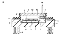
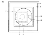
まず、図1〜図3を参照して本発明の第1の実施形態について説明する。ここで、図1は、本発明の第1の実施形態における、圧力調整前の気密封止パッケージの断面図である。また、図2は、本発明の第1の実施形態の気密封止パッケージの上面透視図である。さらに、図3は、本発明の第1の実施形態における、圧力調整時の気密封止パッケージの断面図である。
[First Embodiment]
First, a first embodiment of the present invention will be described with reference to FIGS. Here, FIG. 1 is a cross-sectional view of the hermetically sealed package before pressure adjustment in the first embodiment of the present invention. FIG. 2 is a top perspective view of the hermetically sealed package according to the first embodiment of the present invention. Furthermore, FIG. 3 is a cross-sectional view of the hermetically sealed package at the time of pressure adjustment in the first embodiment of the present invention.
(構成)
まず、図1及び図2を参照して、本実施形態の気密封止パッケージの構成について説明する。
図1に示すように、気密封止パッケージに封止されるMEMSデバイス1は、一部に機械的な駆動部を有するMEMSチップ2と駆動電極(図示しない)が形成された電極基板3とが、金属バンプからなるスペーサ4を介して一定間隔を保ちつつ電気的且つ機械的に接合されて構成されている。このMEMSデバイス1は、箱型に形成されたパッケージ基板5の底面部に例えばハンダからなる接合部材6によって固定されている。電極基板3の駆動電極は、パッケージ基板5の内の電極(図示しない)とボンディングワイヤ7で電気的に接続されている。このボンディングワイヤ7はピン8を経由して気密封止装置外部の回路(図示しない)と電気的に接続されている。
(Constitution)
First, with reference to FIG.1 and FIG.2, the structure of the airtight sealing package of this embodiment is demonstrated.
As shown in FIG. 1, a
また、図1及び図3に示すように、蓋9には外部との光の入出力をするための光学窓10が設けられている。そして、パッケージ基板5と蓋9とは、ハンダや低融点ガラス等からなるシール部材11を介して接合され、これによりパッケージ基板5と蓋9とで形成される内部封止空間(中空部)12が所望の真空度に維持した状態で気密封止される。
As shown in FIGS. 1 and 3, the
さらに、光学窓10の内部封止空間12側の面上には圧力調整部材13が設けられている。圧力調整部材13は、例えばハンダ合金14等の気体発生成分を含まない金属を四角柱状に形成し、その表面を例えばAu膜等の不活性金属膜15で被覆することにより構成されている。ここで、ハンダ合金14の材質は、SnをベースにしてPb、Zn、Al、Sbといった元素が含まれた酸化物を形成しやすい組成であることが望ましい。
Further, a
また、圧力調整部材13の形状や数は調整した真空度(圧力量)によって任意に設定可能であり、本実施形態で示した1つの四角柱状の圧力調整部材に限定されるものではない。例えば、圧力調整部材を複数設けるようにしても良いし、四角柱以外の形状としても良い。また、本実施形態では圧力調整部材13を光学窓10上に設けているが、外部からレーザ光16を照射可能な場所であれば必ずしも光学窓10上に設けなくとも良い。例えば、圧力調整部材13を、パッケージ基板5上やMEMSデバイス1上に設けても構わない。
The shape and number of the
(作用)
次に、図3を参照して第1の実施形態の圧力調整の作用を説明する。
まず、本実施形態の気密封止パッケージを所望の真空度に圧力調整可能な気密封止装置(図示しない)内で気密封止することにより、気密封止パッケージの内部封止空間12は所望の真空度を保ちつつ封止される。このようにして気密封止パッケージが製造される。
(Function)
Next, the operation of the pressure adjustment of the first embodiment will be described with reference to FIG.
First, the hermetically sealed package of the present embodiment is hermetically sealed in a hermetically sealed device (not shown) capable of adjusting the pressure to a desired degree of vacuum. It is sealed while maintaining the degree of vacuum. In this way, an airtight sealed package is manufactured.
光学窓10やシール部材11の周縁部の気密性の低下により、外部から内部封止空間12に微量の気体(主に空気)が流入すると、内部封止空間12の真空度が上昇してMEMSデバイス1の駆動性能が変化する。
When a small amount of gas (mainly air) flows into the
ここで、外部から光学窓10を透過させてレーザ光16を圧力調整部材13に照射して圧力調整部材13に熱エネルギーを加えると、不活性金属膜15がハンダ合金14の中へ拡散し、ハンダ合金14が表面に露出してくる。この結果、図3に示すように、表面に露出したハンダ合金14と内部封止空間12に流入した酸素や水分等からなる気体分子17とが反応して酸化膜を形成したり、気体分子17がハンダ合金14の表面に吸着したりして、ハンダ合金14が気体分子17を吸収する。したがって、内部封止空間12中の気体分子17の数が減って真空度が低下する。ここで、真空度の低下量は、レーザ光16の照射量や照射時間と圧力調整部材13の表面積とによって調整可能である。例えば、レーザ光16の照射量や照射時間を増やすことにより圧力調整部材13に供給されるエネルギー量が増加する。これにより反応が進みやすくなり、真空度が低下する。また、同一のエネルギー供給量であれば圧力調整部材13の表面積を増加させたほうが、反応量が多くなるために真空度が低下する。したがって、レーザ光16の照射量や照射時間と圧力調整部材13の表面積とを調整することによって内部封止空間12内の真空度を所望の値に戻すことが可能である。
Here, when the heat energy is applied to the
(効果)
以上説明したように、第1の実施形態によれば、気密封止パッケージ内の内部封止空間12にArガス等の不活性ガスを充填しなくとも、内部封止空間内の真空度(圧力)を所望の値にすることが可能である。また、圧力調整の際には圧力調整部材13のみに局所的にエネルギーを供給できるために、熱に弱いMEMSデバイスでも圧力調整可能である。
(effect)
As described above, according to the first embodiment, the degree of vacuum (pressure) in the internal sealed space can be obtained without filling the internal sealed
また、第1の実施形態では、光学窓10からレーザ光16を透過させて圧力調整部材13に圧力調整用のエネルギーを供給するために、エネルギー伝達手段として新たな部材を設ける必要がなく製造コストを低く抑えることができるという効果がある。
In the first embodiment, since the
また、圧力調整部材13に安価なハンダ合金14を使用しているために、圧力調整部材13の製造コストも低くできるという効果がある。即ち、後述する他の実施形態と比較して構造がシンプルになり製造コストを低くできる。さらに、圧力調整部材13のハンダ合金14を、Au膜等の不活性金属膜15で被覆しておくことにより、通常時にはハンダ合金14が気体分子17と反応することがなく、不要な真空度の低下も起こらない。
In addition, since an
[第2の実施形態]
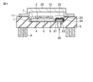
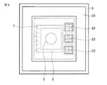
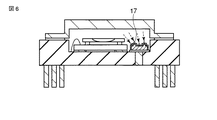
次に、図4〜図6を参照して本発明の第2の実施形態について説明する。ここで、図4は、本発明の第2の実施形態における、圧力調整前の気密封止パッケージの断面図である。また、図5は、本発明の第2の実施形態の気密封止パッケージの上面透視図である。さらに、図6は、本発明の第2の実施形態における、圧力調整時の気密封止パッケージの断面図である。
[Second Embodiment]
Next, a second embodiment of the present invention will be described with reference to FIGS. Here, FIG. 4 is a cross-sectional view of the hermetically sealed package before pressure adjustment in the second embodiment of the present invention. FIG. 5 is a top perspective view of the hermetically sealed package according to the second embodiment of the present invention. Furthermore, FIG. 6 is a cross-sectional view of the hermetic sealed package at the time of pressure adjustment in the second embodiment of the present invention.
(構成)
まず、図4及び図5を参照して、本実施形態の気密封止パッケージの構成について説明する。なお、第1の実施形態と同一の構成については第1の実施形態と同一の参照符号を付すことにより説明を省略する。
(Constitution)
First, with reference to FIG.4 and FIG.5, the structure of the airtight sealing package of this embodiment is demonstrated. In addition, about the structure same as 1st Embodiment, description is abbreviate | omitted by attaching | subjecting the same referential mark as 1st Embodiment.
第2の実施形態においては蓋20が、光学窓を有しないコバール等の金属で構成されている。光学窓を有していないため、蓋20は光を透過させない構造となっている。また、パッケージ基板5には、光学窓の代わりのエネルギー伝達手段として、パッケージ基板5の外部と内部とをつなぐように配置された金属配線体21が設けられている。
In the second embodiment, the
また、圧力調整部材22は、表面に凹凸を形成したSi又はガラス等からなる構造部材23に、CrやTiやCuやAl等の、気体発生成分を含まず且つ比較的酸化しやすい金属膜24を形成し、さらにこの金属膜24をAu膜等の不活性金属膜25で被覆した構造体として構成されている。この圧力調整部材22は、図5に示すように、金属配線体21と接触するように気密封止パッケージの内部封止空間内に複数配置される。
In addition, the
ここで、本実施形態では圧力調整部材22の表面積を増加させるために、圧力調整部材22の表面に凹凸を設けているが、必ずしもそうする必要はなく、圧力の調整量によっては凹凸を設けない平面上の表面にしても構わない。また、圧力調整部材22は第1の実施形態と同様に1つのみ設けるようにしても良い。さらに、圧力調整部材22は、全てが同一のものであっても良いし、圧力の調整量を可変できるように表面積等を異ならせるようにしても良い。
Here, in the present embodiment, in order to increase the surface area of the
(作用)
次に、図6を参照して第2の実施形態の圧力調整の作用を説明する。
第2の実施形態の気密封止パッケージは、第1の実施形態と同様に、所望の真空度に圧力調整可能な気密封止装置(図示しない)内で気密封止することにより製造される。
(Function)
Next, the operation of the pressure adjustment of the second embodiment will be described with reference to FIG.
As in the first embodiment, the hermetic sealing package of the second embodiment is manufactured by hermetically sealing in a hermetic sealing device (not shown) capable of adjusting the pressure to a desired degree of vacuum.
製造後、シール部材11の周縁部の気密性低下により外部から微量の気体が流入すると、内部封止空間12の真空度が上昇してMEMSデバイス1の駆動性能が変化する。
After manufacturing, when a small amount of gas flows in from the outside due to a decrease in the airtightness of the peripheral edge of the
ここで、パッケージ基板5の外表面に露出している金属配線体21に熱26を加えると、金属配線体21を経由して圧力調整部材22に熱26が伝達される。圧力調整部材22に熱エネルギーが加わると、第1の実施形態と同様に、不活性金属膜25が金属膜24へ拡散して金属膜24が表面に露出する。そして、表面に露出した金属膜24に内部封止空間12中にある酸素や水分等の気体分子17が反応して酸化膜を形成したり、表面に吸着したりすることにより内部封止空間12中の気体分子数が減り真空度を低下する。真空度の低下量は加熱温度や時間と圧力調整部材22の表面積により調整できるので、これらを調整することにより、内部封止空間12内部の真空度を所望の値に戻すことが可能である。
Here, when
(効果)
以上説明したように、第2の実施形態によれば、第1の実施形態と同様に気密封止パッケージ内の内部封止空間12にArガス等の不活性ガスを充填しなくとも、内部封止空間12内の真空度(圧力)を所望の値にすることが可能であるとともに、パッケージ基板5に形成した金属配線体21により圧力調整用のエネルギーを供給するために光学窓10が不要である。そのために、外部からの光を遮断する必要があるデバイスや光学窓を必要としないデバイスにも適用できるという効果がある。また、第1の実施形態と同様に、圧力調整の際には圧力調整部材22のみに局所的にエネルギーを供給できるために、熱に弱いMEMSデバイスでも圧力調整可能である。
(effect)
As described above, according to the second embodiment, as in the first embodiment, the
また、圧力調整部材22の表面が凹凸を有しているので、単位面積あたりの表面積を最も大きくとることができ、真空度の低下効果を高めることが可能である。
Further, since the surface of the
さらに、圧力調整部材22を複数設けることにより、圧力調整を段階的に行ったり、複数回行ったりすることが可能である。即ち、圧力調整をした後でさらに内部封止空間12内の真空度が変化した場合でも圧力調整を行うことが可能である。
Further, by providing a plurality of
[第3の実施形態]
次に、図7〜図10を参照して本発明の第3の実施形態について説明する。ここで、図7は、本発明の第3の実施形態における、圧力調整前の気密封止パッケージの断面図である。また、図8は、本発明の第3の実施形態の気密封止パッケージの上面透視図である。また、図9は、本発明の第3の実施形態の圧力調整部材の断面図である。さらに、図10は、本発明の第3の実施形態における、圧力調整時の気密封止パッケージの断面図である。
[Third Embodiment]
Next, a third embodiment of the present invention will be described with reference to FIGS. Here, FIG. 7 is a cross-sectional view of the hermetically sealed package before pressure adjustment in the third embodiment of the present invention. FIG. 8 is a top perspective view of the hermetically sealed package according to the third embodiment of the present invention. FIG. 9 is a sectional view of a pressure adjusting member according to the third embodiment of the present invention. Furthermore, FIG. 10 is a cross-sectional view of the hermetic sealing package at the time of pressure adjustment in the third embodiment of the present invention.
(構成)
まず、図7〜図9を参照して、本実施形態の気密封止パッケージの構成を説明する。なお、第1の実施形態と同一の構成については第1の実施形態と同一の参照符号を付すことにより説明を省略する。
(Constitution)
First, the configuration of the hermetically sealed package of the present embodiment will be described with reference to FIGS. In addition, about the structure same as 1st Embodiment, description is abbreviate | omitted by attaching | subjecting the same referential mark as 1st Embodiment.
上述した第1及び第2の実施形態は、内部封止空間12内の真空度を低下させる方向に圧力調整を行うものであったが、第3の実施形態は内部封止空間12内の真空度を上昇させる方向に圧力調整を行うものである。
In the first and second embodiments described above, pressure adjustment is performed in a direction that lowers the degree of vacuum in the internal sealed
第3の実施形態においては、図9に示すように、圧力調整部材30が、構造部材31と、気体分子発生体32と、蓋部材33と、被覆体35とを有し、パッケージ基板5上のレーザ光16を照射可能な位置に接合部材38によって固定されている。
In the third embodiment, as shown in FIG. 9, the
構造部材31は、Si又はガラス等で構成され、気体分子発生体32を格納するための凹部が形成されている。気体分子発生体32は、ある一定温度以上にならないと揮発しないフロリナート、CO2、H2O、フラックス等の気体発生成分を内包した例えばハンダ等の金属であり、構造部材31に形成された凹部に格納される。蓋部材33は、Siやガラス等から構成される。この蓋部材33は構造部材31の上面に接合され、図7及び図8に示すような微小な貫通孔34が形成されている。被覆体35は、ある一定温度になると溶融するハンダ等の金属膜36の表面を、金膜等の不活性金属膜37で被覆することで構成されている。
The
ここで、本実施形態では、圧力調整部材30を図9に示すような構造体にしたが、圧力調整量によっては、気体発生成分を含んだフラックス(図示しない)を内包したハンダ合金(図示しない)の表面を不活性金属膜で被覆した比較的単純な構造体としても構わない。
Here, in this embodiment, the
また、圧力調整部材30は内部封止空間12内に複数設けるようにしても良いし、第1の実施形態のようなレーザ光照射ではなく、第2の実施形態のように金属配線体を介して熱エネルギーを供給できるようにしても良い。
Further, a plurality of
(作用)
次に、図10を参照して第3の実施形態の圧力調整の作用を説明する。
本実施形態の作用は、第1の実施形態及び第2の実施形態と以下の作用が異なる。
(Function)
Next, the operation of the pressure adjustment of the third embodiment will be described with reference to FIG.
The operation of this embodiment is different from that of the first embodiment and the second embodiment in the following operation.
第3の実施形態の気密封止パッケージは、第1及び第2の実施形態と同様に、所望の真空度に圧力調整可能な気密封止装置(図示しない)内で気密封止することにより製造される。 The hermetic sealing package of the third embodiment is manufactured by hermetically sealing in a hermetic sealing device (not shown) capable of adjusting the pressure to a desired degree of vacuum, as in the first and second embodiments. Is done.
製造後、内部封止空間12内に配置されているMEMSデバイス1や気密封止パッケージの蓋9の内面等の加熱冷却により内蔵物の表面に気体分子が吸着すると、内部封止空間12内の真空度が低下してMEMSデバイス1の駆動性能が変化する。
After the manufacture, when gas molecules are adsorbed on the surface of the built-in object by heating and cooling the
ここで、外部から光学窓10を透過させてレーザ光16を圧力調整部材30に照射して圧力調整部材30に、金属膜36を溶融させ且つ気体分子発生体32から気体を発生させる程度の熱エネルギーを加えると、不活性金属膜37が金属膜36中へ拡散しつつ溶融することにより貫通孔34が露出する。そして、気体分子発生体32から発生した気体分子39が貫通孔34を通って内部封止空間12に放出される。真空度の上昇量は、レーザの照射量や時間と気体分子発生体32に内蔵される気体分子量とにより調整できるので、これらを調整することにより、内部封止空間12内部の真空度を所望の値に戻すことが可能である。
Here, heat is generated so that the
(効果)
以上説明したように、第3の実施形態によれば、圧力調整部材30内に気体分子発生体32を内包させたので、内部封止空間12内の真空度を上昇させるように圧力調整を行うことが可能である。また、第1の実施形態と同様に、圧力調整の際には圧力調整部材30のみに局所的にエネルギーを供給できるために、熱に弱いMEMSデバイスでも圧力調整可能である。
(effect)
As described above, according to the third embodiment, since the
以上実施形態に基づいて本発明を説明したが、本発明は上述した実施形態に限定されるものではなく、本発明の要旨の範囲内で種々の変形や応用が可能なことは勿論である。例えば、上述した第1及び第2の実施形態においては真空度を低下させる圧力調整を、第3の実施形態においては真空度を上昇させる圧力調整を説明したが、これらを組み合わせて使用するようにしても良い。 Although the present invention has been described above based on the embodiments, the present invention is not limited to the above-described embodiments, and various modifications and applications are naturally possible within the scope of the gist of the present invention. For example, in the first and second embodiments described above, the pressure adjustment for lowering the degree of vacuum was explained, and in the third embodiment, the pressure adjustment for raising the degree of vacuum was explained. However, these are used in combination. May be.
さらに、上記した実施形態には種々の段階の発明が含まれており、開示される複数の構成要件の適当な組合せにより種々の発明が抽出され得る。例えば、実施形態に示される全構成要件からいくつかの構成要件が削除されても、上述したような課題を解決でき、上述したような効果が得られる場合には、この構成要件が削除された構成も発明として抽出され得る。 Further, the above-described embodiments include various stages of the invention, and various inventions can be extracted by appropriately combining a plurality of disclosed constituent elements. For example, even if some configuration requirements are deleted from all the configuration requirements shown in the embodiment, the above-described problem can be solved, and this configuration requirement is deleted when the above-described effects can be obtained. The configuration can also be extracted as an invention.
1…MEMSデバイス、2…MEMSチップ、3…電極基板、4…スペーサ、5…パッケージ基板、6…接合部材、7…ボンディングワイヤ、8…ピン、9,20…蓋、10…光学窓、11…シール部材、12…内部封止空間、13,22,30…圧力調整部材
DESCRIPTION OF
Claims (12)
前記蓋と前記基板の少なくとも何れか一方の表面上に設けられ、当該気密封止パッケージに前記デバイスが気密封止された状態で外部からエネルギーを受けて前記中空部内の圧力を調整する少なくとも1つの圧力調整手段と、
前記圧力調整手段に前記エネルギーを伝達するためのエネルギー伝達手段と、
を具備することを特徴とする気密封止パッケージ。 In a hermetic sealing package in which a device is installed in a hollow portion formed by a lid and a substrate and the device is hermetically sealed in a reduced pressure atmosphere.
At least one provided on the surface of at least one of the lid and the substrate and receiving the energy from the outside in a state in which the device is hermetically sealed in the hermetic sealed package to adjust the pressure in the hollow portion Pressure adjusting means;
Energy transmitting means for transmitting the energy to the pressure adjusting means;
A hermetically sealed package comprising:
溝部が設けられた構造部材と、
前記溝部に格納され、ある一定温度以上になった時点で気体を発生する気体分子発生体と、
前記構造部材と接合され、前記気体分子発生体から発生する気体が前記溝部から流出するのを防止するための微小な貫通孔が設けられた蓋部材と、
少なくとも前記蓋部材の前記貫通孔を被覆した金属膜と、
前記金属膜の表面を被覆する不活性金属膜と、
を有することを特徴とする請求項6に記載の気密封止パッケージ。 The structure containing the gas generating component in the inside,
A structural member provided with a groove,
A gas molecule generator that is stored in the groove and generates a gas at a certain temperature or higher; and
A lid member that is joined to the structural member and provided with minute through-holes for preventing the gas generated from the gas molecule generator from flowing out of the groove;
A metal film covering at least the through hole of the lid member;
An inert metal film covering the surface of the metal film;
The hermetically sealed package according to claim 6, further comprising:
Priority Applications (2)
| Application Number | Priority Date | Filing Date | Title |
|---|---|---|---|
| JP2007015152A JP2008182103A (en) | 2007-01-25 | 2007-01-25 | Airtight sealed package |
| US12/018,615 US7936056B2 (en) | 2007-01-25 | 2008-01-23 | Airtight package comprising a pressure adjustment unit |
Applications Claiming Priority (1)
| Application Number | Priority Date | Filing Date | Title |
|---|---|---|---|
| JP2007015152A JP2008182103A (en) | 2007-01-25 | 2007-01-25 | Airtight sealed package |
Publications (1)
| Publication Number | Publication Date |
|---|---|
| JP2008182103A true JP2008182103A (en) | 2008-08-07 |
Family
ID=39725760
Family Applications (1)
| Application Number | Title | Priority Date | Filing Date |
|---|---|---|---|
| JP2007015152A Withdrawn JP2008182103A (en) | 2007-01-25 | 2007-01-25 | Airtight sealed package |
Country Status (2)
| Country | Link |
|---|---|
| US (1) | US7936056B2 (en) |
| JP (1) | JP2008182103A (en) |
Cited By (3)
| Publication number | Priority date | Publication date | Assignee | Title |
|---|---|---|---|---|
| WO2010119573A1 (en) | 2009-04-17 | 2010-10-21 | 株式会社日立製作所 | Inertial sensor and method for manufacturing the same |
| JP2011179821A (en) * | 2010-02-26 | 2011-09-15 | Hitachi Automotive Systems Ltd | Manufacturing method of combined sensor |
| CN110383138A (en) * | 2016-11-20 | 2019-10-25 | 尤尼斯拜特罗有限责任公司 | Tunable MEMS etalon device |
Families Citing this family (12)
| Publication number | Priority date | Publication date | Assignee | Title |
|---|---|---|---|---|
| JP2010141870A (en) * | 2008-11-17 | 2010-06-24 | Panasonic Corp | Silicon microphone module and method for manufacturing the same |
| JP2010161271A (en) * | 2009-01-09 | 2010-07-22 | Panasonic Corp | Semiconductor package |
| US20120106085A1 (en) * | 2009-02-19 | 2012-05-03 | Takao Yamazaki | Vacuum sealed package, printed circuit board having vacuum sealed package, electronic device, and method for manufacturing vacuum sealed package |
| FR2968647A1 (en) * | 2010-12-08 | 2012-06-15 | Kfm Technology | CIRCUIT COMPRISING A COMPONENT COVERED WITH A HOOD, METHOD FOR CARRYING OUT SUCH CIRCUIT AND DEVICE FOR CARRYING OUT SAID METHOD |
| DE102012202183B4 (en) * | 2012-02-14 | 2020-03-19 | Robert Bosch Gmbh | Micromechanical structure and method for producing a micromechanical structure |
| US9343383B2 (en) * | 2012-03-02 | 2016-05-17 | Cree, Inc. | High voltage semiconductor devices including electric arc suppression material and methods of forming the same |
| KR20160023838A (en) | 2013-06-24 | 2016-03-03 | 테크놀로지 이노베이션 모멘텀 펀드 (이스라엘) 리미티드 파트너쉽 | A system and method for color image acquisition |
| DE102014207466A1 (en) * | 2014-04-17 | 2015-10-22 | Robert Bosch Gmbh | Method for adjusting a pressure in a microfluidic device |
| US9556019B2 (en) * | 2015-05-06 | 2017-01-31 | Invensense, Inc. | Cavity pressure modification using local heating with a laser |
| CN107850771B (en) * | 2015-07-15 | 2020-08-28 | 科技创新动量基金(以色列)有限责任合伙公司 | Adjustable MEMS etalon |
| KR102049373B1 (en) | 2015-07-30 | 2019-11-27 | 테크놀로지 이노베이션 모멘텀 펀드 (이스라엘) 리미티드 파트너쉽 | Spectrum Image Processing Method, Spectrum Image Processing System and Control Unit |
| CN112840465A (en) * | 2018-09-26 | 2021-05-25 | 依格耐特有限公司 | MEMS package |
Family Cites Families (7)
| Publication number | Priority date | Publication date | Assignee | Title |
|---|---|---|---|---|
| US6686653B2 (en) * | 2000-06-28 | 2004-02-03 | Institut National D'optique | Miniature microdevice package and process for making thereof |
| US6534850B2 (en) * | 2001-04-16 | 2003-03-18 | Hewlett-Packard Company | Electronic device sealed under vacuum containing a getter and method of operation |
| KR100474455B1 (en) | 2002-11-08 | 2005-03-11 | 삼성전자주식회사 | Method and device for mounting vacumm of micro electro mechanical system at wafer level |
| US7871660B2 (en) * | 2003-11-14 | 2011-01-18 | Saes Getters, S.P.A. | Preparation of getter surfaces using caustic chemicals |
| JP4598432B2 (en) * | 2004-05-12 | 2010-12-15 | 浜松ホトニクス株式会社 | Electronic component and manufacturing method thereof |
| US20050269688A1 (en) * | 2004-06-03 | 2005-12-08 | Lior Shiv | Microelectromechanical systems (MEMS) devices integrated in a hermetically sealed package |
| US7261793B2 (en) * | 2004-08-13 | 2007-08-28 | Hewlett-Packard Development Company, L.P. | System and method for low temperature plasma-enhanced bonding |
-
2007
- 2007-01-25 JP JP2007015152A patent/JP2008182103A/en not_active Withdrawn
-
2008
- 2008-01-23 US US12/018,615 patent/US7936056B2/en not_active Expired - Fee Related
Cited By (6)
| Publication number | Priority date | Publication date | Assignee | Title |
|---|---|---|---|---|
| WO2010119573A1 (en) | 2009-04-17 | 2010-10-21 | 株式会社日立製作所 | Inertial sensor and method for manufacturing the same |
| US8429969B2 (en) | 2009-04-17 | 2013-04-30 | Hitachi, Ltd. | Inertial sensor and method of manufacturing the same |
| JP5497746B2 (en) * | 2009-04-17 | 2014-05-21 | 株式会社日立製作所 | Inertial sensor and manufacturing method thereof |
| JP2011179821A (en) * | 2010-02-26 | 2011-09-15 | Hitachi Automotive Systems Ltd | Manufacturing method of combined sensor |
| CN110383138A (en) * | 2016-11-20 | 2019-10-25 | 尤尼斯拜特罗有限责任公司 | Tunable MEMS etalon device |
| CN110383138B (en) * | 2016-11-20 | 2021-12-28 | 尤尼斯拜特罗有限责任公司 | Tunable etalon device and imaging device |
Also Published As
| Publication number | Publication date |
|---|---|
| US7936056B2 (en) | 2011-05-03 |
| US20080211073A1 (en) | 2008-09-04 |
Similar Documents
| Publication | Publication Date | Title |
|---|---|---|
| US7936056B2 (en) | Airtight package comprising a pressure adjustment unit | |
| JP5343969B2 (en) | Sealed package, printed circuit board, electronic device, and manufacturing method of sealed package | |
| US20140022718A1 (en) | Vacuum sealed package, printed circuit board having vacuum sealed package, electronic device, and method for manufacturing vacuum sealed package | |
| US20070108634A1 (en) | Packaged electronic element and method of producing electronic element package | |
| US20100087024A1 (en) | Device cavity organic package structures and methods of manufacturing same | |
| KR20150059757A (en) | Low temperature hermetic sealing via laser | |
| JP2007537040A (en) | Attachment of getter for vacuum package | |
| US20120266462A1 (en) | Sealed electronic housing and method for the sealed assembly of such a housing | |
| JP6454927B2 (en) | Electronic component and method for manufacturing electronic component | |
| JP3199611B2 (en) | Optical semiconductor element storage package | |
| US20070262440A1 (en) | Sealing structure and method of manufacturing the sealing structure | |
| JP2013021079A (en) | Sealing method of package | |
| JP5078933B2 (en) | Package and package manufacturing method | |
| JP2007206337A (en) | Manufacturing method of optical module | |
| JP2000307368A (en) | Method of manufacturing piezoelectric vibrator | |
| JP2000091690A (en) | Package and getter assembly for LD module | |
| JP2007305736A (en) | Manufacturing method of optical module | |
| CN121128052A (en) | Component packages and methods for manufacturing component packages | |
| JP2001332804A (en) | Cap for semiconductor laser, method of manufacturing the same, and semiconductor laser | |
| JP2002270906A (en) | Thermoelectric module | |
| JP4089609B2 (en) | Electronic device package and method of manufacturing electronic device package | |
| JP2010040767A (en) | Hermetic seal package | |
| KR20070087055A (en) | Semiconductor laser device and manufacturing method thereof | |
| JP2007142176A (en) | Manufacturing method of optical module | |
| JP2010087321A (en) | Mems module |
Legal Events
| Date | Code | Title | Description |
|---|---|---|---|
| A300 | Application deemed to be withdrawn because no request for examination was validly filed |
Free format text: JAPANESE INTERMEDIATE CODE: A300 Effective date: 20100406 |