JP2008196600A - Travel control device for work vehicle - Google Patents
Travel control device for work vehicle Download PDFInfo
- Publication number
- JP2008196600A JP2008196600A JP2007032366A JP2007032366A JP2008196600A JP 2008196600 A JP2008196600 A JP 2008196600A JP 2007032366 A JP2007032366 A JP 2007032366A JP 2007032366 A JP2007032366 A JP 2007032366A JP 2008196600 A JP2008196600 A JP 2008196600A
- Authority
- JP
- Japan
- Prior art keywords
- reverse
- speed
- lever
- trunnion shaft
- transmission
- Prior art date
- Legal status (The legal status is an assumption and is not a legal conclusion. Google has not performed a legal analysis and makes no representation as to the accuracy of the status listed.)
- Withdrawn
Links
- 230000007935 neutral effect Effects 0.000 claims abstract description 39
- 230000005540 biological transmission Effects 0.000 claims description 109
- 230000002706 hydrostatic effect Effects 0.000 claims description 21
- 230000002159 abnormal effect Effects 0.000 claims description 8
- 238000010586 diagram Methods 0.000 description 7
- 230000035945 sensitivity Effects 0.000 description 7
- 230000000994 depressogenic effect Effects 0.000 description 6
- 238000001514 detection method Methods 0.000 description 5
- 230000005856 abnormality Effects 0.000 description 3
- 238000006073 displacement reaction Methods 0.000 description 3
- 230000001133 acceleration Effects 0.000 description 2
- 238000010276 construction Methods 0.000 description 2
- 230000001276 controlling effect Effects 0.000 description 2
- 230000000881 depressing effect Effects 0.000 description 2
- 230000035939 shock Effects 0.000 description 2
- 208000019901 Anxiety disease Diseases 0.000 description 1
- 230000036506 anxiety Effects 0.000 description 1
- 230000008878 coupling Effects 0.000 description 1
- 238000010168 coupling process Methods 0.000 description 1
- 238000005859 coupling reaction Methods 0.000 description 1
- 230000000694 effects Effects 0.000 description 1
- 239000010720 hydraulic oil Substances 0.000 description 1
- 230000007257 malfunction Effects 0.000 description 1
- 238000000034 method Methods 0.000 description 1
- 230000001105 regulatory effect Effects 0.000 description 1
Images


Landscapes
- Control Of Fluid Gearings (AREA)
Abstract
【課題】前後進レバーを前進側に操作して、変速レバーを所定位置(特に高速位置、また特に副変速レバーを高速位置)にして前進中に前後進レバーを一気に後進側に操作しても、機体が急激に後進してしまわない作業車両の走行制御装置を提供すること。
【解決手段】トラニオン軸回動用の油圧シリンダ93の作動量を設定する変速レバー20と、HST34を前進側又は後進側に設定することを決める前後進レバー10と、レバー10が前進側から後進側に切り換えられたときはシリンダ93の目標位置への変化速度を中立位置から後進側又は前進側に操作する動作速度より低速にする制御をする走行制御装置であり、レバー10を前進側から後進側に切り換えた時は、油圧シリンダ93の目標位置への変化速度は中立位置から後進(或いは前進)側へ操作した時の動作速度より低速になるので、例えば前進側から後進側にいきなり高速で動いてしまうことを防止する。
【選択図】図12An object of the present invention is to operate a forward / reverse lever in a predetermined position (especially a high-speed position, and particularly, a sub-shift lever in a high-speed position) by operating the forward / reverse lever to the forward side, To provide a travel control device for a work vehicle in which the airframe does not reverse rapidly.
A shift lever 20 for setting an operation amount of a hydraulic cylinder 93 for turning a trunnion shaft, a forward / reverse lever 10 for determining that an HST 34 is set to a forward side or a reverse side, and a lever 10 from a forward side to a reverse side Is a travel control device for controlling the speed of change of the cylinder 93 to the target position to be lower than the operation speed operated from the neutral position to the reverse side or the forward side, and the lever 10 is moved from the forward side to the reverse side. When switching to, the speed of change of the hydraulic cylinder 93 to the target position is slower than the operating speed when operating from the neutral position to the reverse (or forward) side, so for example, the hydraulic cylinder 93 moves rapidly from the forward side to the reverse side. To prevent it.
[Selection] Figure 12
Description
この発明は、農業用、建築用、運搬用等のトラクタなどの作業車両で用いられる静油圧式無段変速装置(以下、HSTということがある)と噛合式変速装置からなる変速装置を有する走行車両の走行制御装置に関する。 The present invention has a transmission having a hydrostatic continuously variable transmission (hereinafter sometimes referred to as HST) used in work vehicles such as tractors for agriculture, construction, and transportation, and a transmission including a meshing transmission. The present invention relates to a vehicle travel control device.
静油圧式無段変速装置と噛合式変速装置からなる変速装置を備えたトラクタなどの作業車両が、例えば特開2002−250437号公報に記載されている。 A work vehicle such as a tractor including a transmission including a hydrostatic continuously variable transmission and a meshing transmission is described in, for example, Japanese Patent Application Laid-Open No. 2002-250437.
前記作業車両のHSTと噛合式変速装置からなる変速装置では、前後進レバーの操作位置の検出によりトラニオン軸の前進側か後進側かの回動方向を決め、変速レバーの操作量に基づきトラニオン軸を回動させる油圧シリンダの作動量を調整してHSTの出力を行っている。
前記変速装置において変速レバーによるHSTのトラニオン軸の回動角度の調整は変速レバーの作動量を検出する検出センサの検出値に応じてコントローラの指令により油圧シリンダの作動量を調整してトラニオン軸を回動させて行っている。 In the transmission, the rotation angle of the HST trunnion shaft by the shift lever is adjusted by adjusting the operation amount of the hydraulic cylinder according to the command of the controller according to the detection value of the detection sensor for detecting the operation amount of the shift lever. It is rotating.
しかし、前後進レバーを前進側から中立位置を経由して後進側に一気に操作すると、機体は急停止した後に一気に後進してしまうという問題点がある。すなわち前後進レバーを前進側に操作して、変速レバーを所定位置(特に高速位置、また特に副変速レバーを高速位置)にして前進中に前後進レバーを一気に後進側に操作すると、機体が急激に後進してしまうことがある。 However, if the forward / reverse lever is operated from the forward side to the backward side through the neutral position, there is a problem in that the aircraft moves backward after a sudden stop. That is, if the forward / reverse lever is operated to the forward side, the shift lever is moved to a predetermined position (especially the high speed position, and particularly the auxiliary transmission lever is at the high speed position), and the forward / reverse lever is operated all at once in the forward direction, the aircraft will suddenly May go backwards.
本発明の課題は、前後進レバーを前進側に操作して、変速レバーを所定位置(特に高速位置、また特に副変速レバーを高速位置)にして前進中に前後進レバーを一気に後進側に操作しても、機体が急激に後進してしまわない作業車両の走行制御装置を提供することである。 The object of the present invention is to operate the forward / reverse lever at a predetermined position (especially at the high speed position and particularly at the high speed position) by operating the forward / reverse lever to the forward side and operating the forward / reverse lever at a stretch during the forward movement. Even so, it is to provide a travel control device for a work vehicle in which the airframe does not reverse rapidly.
本発明の上記課題は、次の解決手段で解決される。
すなわち、請求項1記載の発明は、エンジン(5)の動力をトラニオン軸(92)の回動角度を調整して出力する静油圧式無段変速装置(34)と該静油圧式無段変速装置の出力を複数の変速段に変更して出力する噛合式変速装置(38)を含む変速装置と、静油圧式無段変速装置(34)のトラニオン軸(92)の回動角度を決めるトラニオン軸回動用の油圧シリンダ(93)と、トラニオン軸回動用の油圧シリンダ(93)の作動量を設定する変速レバー(20)と、車両を前進側又は後進側に作動させるべく静油圧式無段変速装置(34)を前進側に設定するか、後進側に設定するかを決める前後進レバー(10)と、該前後進レバー(10)が前進側から後進側に切り換えられたときはトラニオン軸(92)回動用の油圧シリンダ(93)の目標位置への変化速度を中立位置から後進側又は前進側に操作する動作速度より低速にするコントローラ(90)とを備えた作業車両の走行制御装置である。
The above-mentioned problem of the present invention is solved by the following means.
That is, according to the first aspect of the present invention, the hydrostatic continuously variable transmission (34) that outputs the power of the engine (5) by adjusting the rotation angle of the trunnion shaft (92) and the hydrostatic continuously variable transmission. A transmission including a meshing transmission (38) for changing the output of the apparatus to a plurality of shift speeds and a trunnion for determining the rotation angle of the trunnion shaft (92) of the hydrostatic continuously variable transmission (34) A hydraulic cylinder for pivoting the shaft (93), a shift lever (20) for setting the operation amount of the hydraulic cylinder for pivoting the trunnion shaft (93), and a hydrostatic stepless to continuously move the vehicle forward or backward A forward / reverse lever (10) that determines whether the transmission (34) is set to the forward side or the reverse side, and a trunnion shaft when the forward / reverse lever (10) is switched from the forward side to the reverse side (92) Rotating hydraulic cylinder ( 3) a travel control device for a working vehicle having a controller (90) to slower than the operating speed to manipulate the rate of change of the target position to the reverse side or the forward side from the neutral position.
請求項2記載の発明は、エンジン(5)の動力をトラニオン軸(92)の回動角度を調整して出力する静油圧式無段変速装置(HST)(34)と該静油圧式無段変速装置の出力を複数の変速段に変更して出力する噛合式変速装置(38)を含む変速装置と、静油圧式無段変速装置(34)のトラニオン軸(92)の回動角度を決めるトラニオン軸回動用の油圧シリンダ(93)と、トラニオン軸回動用の油圧シリンダ(93)の作動量を設定する変速レバー(20)と、車両を前進側又は後進側に作動させるべく静油圧式無段変速装置(34)を前進側に設定するか、後進側に設定するかを決める前後進レバー(10)と、該前後進レバー(10)の作動により静油圧式無段変速装置(34)の前進側と後進側の設定をそれぞれ行う前進側設定手段(10a)と後進側設定手段(10b)と、該前後進レバー(10)の前進側設定手段(10a)と後進側設定手段(10b)が異常時には変速レバー(20)の所定の作動範囲を前進側から後進側まで変速可能に変更するコントローラ(90)とを備えた作業車両の走行制御装置である。
The invention according to
請求項1記載の発明によれば、前後進レバー(10)を前進側から後進側に切り換えた時は、トラニオン油圧シリンダ(93)の目標位置への変化速度は中立位置から後進(あるいは前進)側へ操作した時の動作速度より低速になるので、たとえば前後進レバー(10)を急操作しても、前進側から後進側にいきなり高速で動いてしまうことを防止できる。 According to the first aspect of the invention, when the forward / reverse lever (10) is switched from the forward side to the reverse side, the speed of change of the trunnion hydraulic cylinder (93) to the target position is reverse (or forward) from the neutral position. Therefore, even if the forward / reverse lever (10) is suddenly operated, for example, it is possible to prevent sudden movement from the forward side to the reverse side at a high speed.
請求項2記載の発明によれば、前後進レバー(10)の前進側設定手段(10a)と後進側設定手段(10b)が異常時には変速レバー(20)の所定の作動範囲を前進側から後進側まで変速可能に変更することで、変速レバー(20)のみで前後進が可能となる。 According to the second aspect of the present invention, when the forward side setting means (10a) and the reverse side setting means (10b) of the forward / reverse lever (10) are abnormal, the predetermined operating range of the speed change lever (20) is reversed from the forward side. By changing so that the speed can be changed to the side, it is possible to move forward and backward only with the speed change lever (20).
以下、図面に基づいて、本発明の実施の形態を説明する。
なお、本明細書において作業車両の前進方向に向かって左右方向をそれぞれ左、右といい、前進方向を前、後進方向を後ろという。
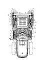
作業車両の一例としてトラクタを例に以下説明する。図1に全体側面図、図2に図1のトラクタの平面図、図3は図1のトラクタの変速装置の動力線図、図4は該変速装置の制御ブロック図を示す。
Hereinafter, embodiments of the present invention will be described with reference to the drawings.
In this specification, the left and right directions in the forward direction of the work vehicle are referred to as left and right, respectively, the forward direction is referred to as front, and the reverse direction is referred to as rear.
Hereinafter, a tractor will be described as an example of a work vehicle. 1 is an overall side view, FIG. 2 is a plan view of the tractor of FIG. 1, FIG. 3 is a power diagram of the transmission of the tractor of FIG. 1, and FIG. 4 is a control block diagram of the transmission.
図1〜図3に示すトラクタは機体の前後部に前輪2、2と後輪3、3を備え、機体の前部に搭載したエンジン5の回転動力を伝動ケース内の変速装置によって適宜減速して、これらの前輪2、2と後輪3、3に伝えるように構成している。
The tractor shown in FIGS. 1 to 3 includes
機体の中央のハンドルポスト6にはステアリングハンドル7が支持され、その後方には座席9が設けられている。ステアリングハンドル7の下方には機体の進行方向を前後方向に切換える前後進レバー10が設けられている。この前後進レバー10を前側に移動させると機体は前進し、後方へ移動させると後進する。またハンドルポスト6を挟んで前後進レバー10の反対側にはアクセルレバー11が設けられ、またステップフロア13の右コーナ部にはアクセルペダル15と左右のブレーキペダル16,17が配置され、ステップフロア13の左コーナ部にはクラッチペダル19が配置されている。
A
また、1速から8速まで変速段を選択可能な変速レバー20は操縦席9の左前方部にあり、低速、中速、高速及び中立のいずれかの位置を選択できる副変速レバー21はその後方にあり、さらにその後方に1〜3速と中立位置を選択できるPTO変速レバー23が設けられている。さらに操縦席9の右側には作業機(図示せず)の高さを設定するポジションレバー24と圃場の耕耘深さを自動的に設定する自動耕深レバー25、これらのレバー24,25の後ろに作業機の右上げスイッチ27と右下げスイッチ28が配置され、更にその後ろに自動水平スイッチ29(オンでトラクタの絶対水平位置(圃場面に対する水平でなく、地球の水平面に対して水平を保つ)とバックアップスイッチ30(オンで前後進レバー10が後進位置にあるとき作業機上げ用リンク31が作業機を上昇させる)が配置されている。また、機体の後方には作業機(図示せず)を連結する前記リンク31が設けられている。
A
図3は、本実施例の静油圧式無段変速装置34を有するトラクタの走行伝動系を表した線図である。エンジン5の回転動力はペダル操作式のクラッチペダル19の踏み込みで作動するメインクラッチ32に伝えられた後、HST入力軸33からHST34に伝達される。HST34は容量可変式の油圧ポンプ34aと定容量式の油圧モータ34bを備えた油圧閉回路34cを備えており、HST入力軸33から導入された動力により油圧ポンプ34aを作動させて、油圧ポンプ34aに設けられた斜板34dの傾斜角度に応じた圧油を油圧閉回路34cから油圧モータ34bに供給し、該油圧モータ34bにより走行出力軸36を駆動させて噛合式の変速装置38へ動力を伝達させる。
FIG. 3 is a diagram showing a traveling transmission system of a tractor having the hydrostatic continuously
噛合式の変速装置38の副変速クラッチ39は図3の左右にスライド可能であり、図示する位置にあるときは走行出力軸36からの動力がギア41を介して高速段ギア42から副変速クラッチ39へ、該副変速クラッチ39から変速軸43のギア45に伝達され、変速軸43の回動がデフ装置46を介して後輪3が副変速高速段の走行速度で駆動される。
The
また、副変速クラッチ39を図3に示す位置から右側に移動して、副変速クラッチ39が変速軸43のギア45と中速段ギア47に係止すると、走行出力軸36からの動力がギア41を介してギア49からギア50、ギア51及びギア47を順次経由して副変速クラッチ39へ伝達され、さらに該副変速クラッチ39から変速軸43のギア45に伝達され、変速軸43の回動がデフ装置46を介して後輪3が副変速中速段の走行速度で駆動される。
Further, when the
副変速クラッチ39がさらに右側に移動して変速軸43のギア45と低速ギア55に係止すると、走行出力軸36からの動力がギア41を介してギア49からギア56へ、さらにギア56からギア57へ伝達され、ギア57と同軸のギア55から副変速クラッチ39へ、さらに該副変速クラッチ39から変速軸43のギア45に伝達され、変速軸43の回動がデフ装置46を介して後輪3が副変速低速段の走行速度で駆動される。
When the
また、副変速クラッチ39のスライド位置が左右いずれの側にあっても、変速軸43からの出力がギア53、59、60等を順次経由して前輪出力軸61に伝達される。このとき油圧クラッチ63が接続していると、デフ装置65を介して前輪2が後輪3と共に駆動する四輪駆動となり、また油圧クラッチ64が接続していると、前輪増速の四輪駆動となる。油圧クラッチ63と油圧クラッチ64が共に接続することはなく、また油圧クラッチ63と油圧クラッチ64が共に接続していないと後輪3のみが駆動する二輪駆動となる。
Even if the sliding position of the
一方、HST入力軸33から容量可変式の油圧ポンプ34aに入力された動力はポンプ出力軸66からPTO用の駆動系に伝達される。PTO用の駆動系にはPTO正逆クラッチ67とPTO副変速クラッチ68があり、トラクタが路上走行時は前記クラッチ67,68のいずれか一方または両方が非接続状態であり、作業機を駆動させるPTO駆動系は駆動されない。
On the other hand, the power input from the HST input shaft 33 to the variable displacement hydraulic pump 34a is transmitted from the
圃場内での作業機を用いる作業時は、アクセルレバー11を操縦者側(手前)に引いてエンジン回転数を定格回転数、または定格回転数以上から最大回転数の一定回転にしているのでHST入力軸33とポンプ出力軸66が同じ回転数で一定回転する。図3に示す状態は中立状態であり、ポンプ出力軸66と直結しているPTO軸69が共に回転する。
When working with the work implement in the field, the HST is set because the engine speed is set to the rated speed or a constant speed from the rated speed to the maximum speed by pulling the accelerator lever 11 toward the operator (front side). The input shaft 33 and the
PTO正逆クラッチ67を図示左方向にスライドさせるとPTO正逆クラッチ67がPTO軸69のギア70とギア71に噛合するので、PTO軸69の動力はギア70,PTO正逆クラッチ67,ギア71,ギア71a,ギア72,ギア74,ギア78,ギア77,ギア76を順次介してPTO伝達軸75を駆動させる(PTO逆転)。また、PTO正逆クラッチ67を図示右方向にスライドさせると、PTO軸69の動力はギア70,PTO正逆クラッチ67,ギア73,ギア77,ギア76を順次介してPTO伝達軸75を駆動させる(PTO正転)。
When the PTO forward / reverse clutch 67 is slid in the left direction in the figure, the PTO forward / reverse clutch 67 meshes with the
ギア72と一体のギア74の駆動に連動するギア78からの動力もPTO伝達軸75に伝達され、PTO副変速クラッチ68が図示位置より最も左方向に移動した位置にあると、ギア79とギア80を介してギアドック81がPTO副変速クラッチ68に設けられたギアドック83と噛合してPTO駆動軸84によりPTO1速が得られる。またPTO副変速クラッチ68が図示位置から左または右方向に移動すると、それぞれの場合に噛合するPTO副変速低速段ギア85またはPTO副変速高速段ギア86に動力が伝達され、ギア85,ギア68a,PTO駆動軸84へ順次動力が伝達されるとPTO2速が得られ、また、ギア86,ギア68b,PTO駆動軸84へ順次動力が伝達されるとPTO3速が得られる。
The power from the
上記構成のトラクタは路上走行時にはクラッチペダル19を踏み込み、副変速レバー21を路上走行に適した位置(基本は高速位置であり、中速位置または低速位置にする場合もある)に設定する。次いで変速レバー20を任意の位置に移動する。変速レバー20は最低速1速から最高速8速まで選択可能であるが、路上走行時の基本は8速である。
The tractor having the above-described configuration depresses the
次いで前後進レバー10を前進側または後進側に移動し、クラッチペダル19をゆっくり離しながら(メインクラッチ32を接続して)アクセルペダル15を踏んでエンジン回転数を上げていく。このときアクセルペダル15を最大限に踏み込んでも、最大速度は変速レバー20の最大速度段(8速)の位置に規制される。
Next, the forward /
また、圃場内での作業時はクラッチペダル19を踏み込んだ後、副変速レバー21を適宜の位置(基本は低速または中速位置)に設定する。次いで変速レバー20を任意の位置(作業の種類に応じて1速から8速まで選択可能)に移動し、前後進レバー10を前進位置に移動させる。アクセルレバー11を操縦者側(手前)に移動してエンジン回転数を定格回転数または定格回転数以上の最大回転数までの間に設定する。次いでクラッチペダル19を離しながら(メインクラッチ32を接続して)前進させる。このときエンジン回転数は定格回転数または定格回転数以上の最大回転数までの間に設定されるが、作業速度は変速レバー20の位置で規制される。
Further, when working in the field, after depressing the
なお、圃場内での作業機を使用する作業時にはアクセルペダル15は使用しないで、アクセルレバー11を用いる。また、路上走行時はアクセルペダル15を使用し、アクセルレバー11は使用しない。路上走行時はアクセルペダル15を操作することで自動車操縦時と同じ感覚で操縦でき、また圃場内での作業時はエンジン回転を一定に保持しなくてはならないため、アクセルペダル15では操縦が難しい。そこで前記作業時にはアクセルレバー11を操作し、かつ前記作業時にはアクセルレバー11から手を離しても元に戻らないので、操縦したアクセル位置に保持して一定エンジン回転数を保つことができる。
Note that the accelerator pedal 11 is used instead of the
図5にはハンドルポスト6と操縦席付近の機体と変速レバー20のみの左側面図を示す。また図6には変速レバー20の基部付近の拡大図を示す。変速レバー20は1〜8速まで速度段を変更可能であり、各速度段に対応するポジション位置を検出できるポジションセンサ20aが該レバー20の基部に設けられている。前記ポジションセンサ20aの検出値はコントローラ90(図4)に出力される。
FIG. 5 shows a left side view of only the handle post 6, the airframe in the vicinity of the cockpit, and the
また図7、図8には変速装置ケース91の平面図(図7(a)、図8(a))と該変速装置ケース91内に収納されているHST34の平面図(図7(b)、図8(b))を示す。また図9には図8(a)の矢印A方向から見た変速装置ケース91の側面図を示す。図5〜図9に示すようにHST34のトラニオン軸92を回動させる油圧シリンダ93と変速装置ケース91の外部に突出した部分のトラニオン軸92を連結するリンク機構95を変速装置ケース91の外壁部分に取り付けている。
7 and 8 show a plan view of the transmission case 91 (FIGS. 7A and 8A) and a plan view of the
シリンダ93のピストンロッド93aの先端部に回動自在に一端を接続したアーム95aの他端を変速装置ケース91の外壁に回動自在に支持させ、さらに該アーム95aのもう一方の端部には該アーム95aの長手方向に直交する方向に設けたロッド95bの一端が回動自在に設けられ、さらにこのロッド95bの他端には回動自在な短いアーム95cを介してアーム95aと略平行な方向に長さ調節可能なロッド95dの端部を回動自在に連結する。該長さ調節可能なロッド95dの他端は回動自在に短いアーム95eの一端に連結し、該短いアーム95eの他端にはボス95fが固定している。
The other end of the
ボス95fは、ボルト95pで軸95qに固定されている。軸95qは変速装置ケース91に対して回転自在に支持されており、軸95qの一端にはプレート95gが固着している。プレート95gの他端はリンクアーム95hにピン95rを介して回動自在に連結し、リンクアーム95hはトラニオン軸92と一体のカム95jに回動自在に連結している。ここで、カム95jはボス95sに固着し、ボス95sはボルト95tによりトラニオン軸92に固定されている。
The
また、プレート95gとリンクアーム95hはピン95rにより連結されているが、該ピン95rによる連結部は軸95qを回動支点として変速装置ケース91に固定された扇状部材95kの円弧状の長穴95k1内を摺動自在になっており、またピン95rが長穴95k1内だけを摺動可能なためにカム95jの回動範囲もピン95rの摺動に連動する範囲内に規制される。
The plate 95g and the
上記リンク機構95により油圧シリンダ93の作動が前記アーム95aやロッド95dなどに連動してカム95jがトラニオン軸92と共に回動することになる。また、カム95jの側面が変速装置ケース91に支持されたローラ95mの側面に当接しながらシリンダ93によりカム95jが回動する。
By the
トラニオン油圧シリンダ93の作動によるトラニオン軸92の回動位置を検出するポジションセンサ92a(図7)は回動軸93dの回動度合いを検出する構成である。ポジションセンサ92aはロッド95dの先端部のアーム95eの接続部とは反対側に回動自在に一端が設けられたアーム93cの他端に連結されている。これにより、ポジションセンサ92aはトラニオン軸92の動き(位置)を検出することになる。トラニオン軸92のポジションセンサ92aはトラニオン軸回動用油圧シリンダ93のピストンロッド93aの前進側の最大伸張位置に設けたストッパ93eと後進側の最少短縮位置に設けたストッパ93f(図9)の各設定位置をそれぞれトラニオン軸92の回動可能な範囲とする基準値とする。またカム95jの凹部95j1にローラ95mが嵌り込む位置をトラニオン軸92の中立位置とし、これも基準値とする。これらポジションセンサ92aで検出する各設定位置を基準位置としてコントローラ90のメモリ(EEPROM)に記憶させておく。こうしてポジションセンサ92aで検出する各設定位置を基準位置としてコントローラ90の指令で作動する油圧シリンダ93によるリンク機構95の作動量のバラツキを吸収させる。
A
図7に示す状態はトラニオン軸92がHST34の油圧ポンプ34aの斜板34dを車両前進側に向けて配置した状態を示しており、図8の変速装置ケース91の平面図(図8(a))と該変速装置ケース91内に収納されているHST34の平面図(図8(b))に示す状態はHST34の油圧ポンプ34aの斜板34dを中立位置に向けた状態を示しており、カム95jの凹部95j1に対してローラ95mが嵌り込む位置がトラニオン軸92の中立位置である。なお、ローラ95mは図8(b)の矢印x方向からバネで押されている。また図10の変速装置ケース91の平面図(図10(a))と該変速装置ケース91内に収納されているHST34の平面図(図10(b))を示す状態はHST34の油圧ポンプ34aの斜板34dを後進側に向けて配置した状態を示している。
7 shows a state where the
図11は前後進レバー10の基部に設けたシフトスイッチ10a,10bの配置とその作動態様を示す図である。図11(a)と図11(c)には前後進レバー10が前進位置と後進位置にある場合の前後進レバー10の基部に設けた前進シフトスイッチ10aと後進シフトスイッチ10bが作動する配置図をそれぞれ示し、図11(b)には前後進レバー10が中立位置にある場合に前進シフトスイッチ10aと後進シフトスイッチ10bのいずれにも当接しない場合の配置図を示す。
FIG. 11 is a diagram showing the arrangement of
上記前後進レバー10の前進シフトスイッチ10aが作動するように前後進レバー10を中立位置から前進側に倒すと前進方向に動かす準備ができ、前後進レバー10の後進シフトスイッチ10bが作動するように前後進レバー10を中立位置から後進側に倒すと後進方向に動かす準備ができる。なお、車両の前進方向と後進方向への加速はあくまで変速レバー20で行う。
When the forward /
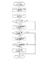
図12のフローチャートに示すように、コントローラ90は前後進レバー10を前進側から後進側に切り換えた時は、トラニオン油圧シリンダ93の目標位置への動作変化速度(X)を中立位置にある前後進レバー10を後進側又は前進側に操作した時の動作変化速度(Y)より低速(X<Y)とする。
As shown in the flowchart of FIG. 12, when the
例えば前進8速で走行中に前後進レバー10を中立位置を経由させて後進側に移動させてもコントローラ90は中立位置を無視して、いきなり後進8速になって、高速で後進するるおそれがあるので、中立位置にある前後進レバー10を後進側又は前進側に操作した時の動作変化速度より低速で変更して、前後進レバー10の前後進切替時の変速ショックを低減する。
For example, even if the forward /
また、前後進レバーシフトスイッチ10a,10bが異常時(例えば、前進シフトスイッチ10aと後進シフトスイッチ10bが共にオンになる)は、変速レバー20でトラニオン軸92の回動角度センサ92aをコントローラ90により前進端から後進端まで指定可能とする。例えば8速〜5速までは前進側とし、4速を中立位置、3速〜1速までを後進側としてシフトスイッチ10a,10bが故障、あるいはその配線のショート等があっても変速レバー20のみで前後進が可能とする。
Further, when the forward / reverse lever shift switches 10a and 10b are abnormal (for example, both the
前記変速レバー20のみで前後進が可能とする手順は、シフトスイッチ10a,10bの異常発生後、トラニオン油圧シリンダ93を一度中立位置に戻し、このときのトラニオン軸92の回動角度センサ92aの中立指示位置を変速レバー20が検出すると、その位置を中立位置としてその後の変速レバー20の操作に従って前進側あるいは後進側へのトラニオン油圧シリンダ93の出力を行う構成としても良い。
The procedure for allowing the
こうすると、シフトスイッチ10a,10bの異常発生時に変速レバー20がどの位置にあるかによって前進走行中に突然後進走行になったり、走行速度が変化するような不具合が回避でき、しかも前後進シフトスイッチ10a,10bの異常時でも走行が可能となる。
In this way, it is possible to avoid problems such as sudden reverse travel during forward travel or changes in travel speed depending on the position of the
また、変速レバーポジションセンサ20aの異常時にはトラニオン軸92の設定目標値は最低速(1速)とすることでゆっくり走行させてセンサ20aの異常時の安定性を確保する。
In addition, when the shift
さらに、トラニオン油圧シリンダポジションセンサ92aの異常時にはトラニオン軸92の回動角度がどの程度であるのか検出できていない状態にあるので、トラニオン油圧シリンダ93の出力を禁止し、ブザーを連続吹鳴する構成とする。
Further, when the trunnion hydraulic
この状態になった時に、主クラッチ32を切った状態で前後進レバー10を操作した時は操作された方向(前進あるいは後進側)に規定時間の間はトラニオン油圧シリンダ93を作動させて、変速レバー20の操作位置に応じたトラニオン軸92の回動位置で走行を可能としても良い。
In this state, when the forward /
このように主クラッチ32を切った時はエンジン動力は変速装置に入力されない状態になるため、この時だけはトラニオン油圧シリンダ93の作動を可能にすることで、危険な状態を回避すると同時にトラニオン油圧シリンダポジションセンサ92aの故障時でも、次に主クラッチ32が入ったときに前進又は後進のどちらにも走行が可能となり、圃場等で異常が発生した場合でも移動が可能となる。
Since the engine power is not input to the transmission when the main clutch 32 is disengaged in this manner, the trunnion
また、次に主クラッチ32が入ったときに副変速段が低速位置である時にのみ走行可能とする構成にしても良い。これは、主クラッチ32を切った状態でトラニオン油圧シリンダ93を作動させて、変速レバー20の操作位置に応じたトラニオン軸92の回動位置で走行を可能としただけでは、トラニオン軸92の回動位置が最高速位置になってしまっていることもあり、また副変速段が高速位置である時も比較的高速走行になる可能性もあるので、そのような不具合を避けることができる。
Further, it may be configured such that the next time the main clutch 32 is engaged, the vehicle can run only when the sub-speed is in the low speed position. This is because if the trunnion
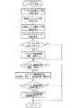
図13のフローチャートに示すように、クラッチペダル19が踏まれた時は、変速レバー20と前後進レバー10がどの位置にあっても、トラニオン軸92の回動角度が中立域に入っていなければ、中立域に入るよう油圧シリンダ93を作動調節する構成を採用しても良い。
As shown in the flowchart of FIG. 13, when the
従来、HST34と変速レバー20と前後進レバー10を機械的なリンク構成で連結しているが、その安全性確保のためにもHST34の中立域を過大にとっている。そのため、クラッチペダル19を踏むと、機械的なリンク構成で走行系を遮断しているが、HST34側は作動停止しているわけでない(HSTの斜板は中立になっていないので、回っている。)ので無駄な動力を消費しているため、HST34の耐久性が悪くなる。
そこで、機械的なリンク構成の連結機構を回避して、上記したフローに従い電気的に油圧シリンダ93を作動させることでエンジン5の始動時の前段としての安全確保が可能となる。
Conventionally, the
Therefore, it is possible to ensure safety as a pre-stage when the engine 5 is started by avoiding the coupling mechanism having a mechanical link configuration and electrically operating the
また、図14のフローチャートに示すように、クラッチペダル19を踏んで、その後、離した時は、主クラッチ32を接続した時のショックを緩和するため、一定時間(例えば0.3秒)毎あるいは、段階的に鈍感から敏感に、徐々に戻すように変速レバー20の対応する変速位置にトラニオン軸92の回動角度位置を調節する構成にすることでエンジン始動時の前段としての安全確保が可能となる。
Also, as shown in the flowchart of FIG. 14, when the
さらに、図15のフローチャートに示すように、トラニオン軸92の回動角度調節による車両の増速時は、一定時間(変速速度が追従するまで、例えば0.5秒)は、耕深制御を敏感(作業機の昇降度合いをパルス間隔を短くする油圧パルス制御などで行う)にする。また、トラニオン軸92の回動角度調節による減速時は、一定時間(変速速度が追従するまで、例えば0.5秒)は、耕深制御を鈍感(作業機の昇降度合いをパルス間隔を長くする油圧パルス制御などで行う)にする。
Further, as shown in the flowchart of FIG. 15, when the vehicle speed is increased by adjusting the rotation angle of the
なお、耕深調整ダイヤル44で耕深を設定し、耕深感度スイッチ40で耕深感度を設定するが、図15のフローチャートでトラニオン軸92の回動角度調節による車両の増減速時にはさらに耕深感度スイッチ40で設定した感度に対して敏感または鈍感にする。
Note that the tilling depth is set with the tilling
上記制御は増速時は、作業機に負荷がかかるため、早い追従が望ましい。これは増速時には機体前上がりになるので作業機は下降しようとして耕深さが大きくなり過ぎ、かつ、負荷がかかり過ぎるためである。また、減速時は鈍感でよいので、エンジンブレーキがかかっているため作業機をゆっくり目に動かす方が整地性がよい。なお、このとき耕深さが所定範囲内にあるように耕深調整ダイヤル44で設定した値になるように自動制御する。 なお、デプスセンサ58(図4)は耕深調整ダイヤル44で設定した深さとなるように検出して制御をし、またストロークセンサ48(図4)でトラニオン油圧シリンダ93のストロークを検出し、増速か減速かを判断する。
In the above control, when the speed is increased, a load is applied to the work machine, so it is desirable to follow up quickly. This is because when the speed is increased, the front of the machine is raised, so that the working machine tends to descend and the plowing depth becomes too large and the load is excessively applied. In addition, since insensitivity is sufficient when decelerating, it is better to level the ground by moving the work implement slowly to the eyes because the engine brake is applied. At this time, the plowing depth is automatically controlled so as to be a value set by the plowing
また、図16のフローチャートに示すように、トラニオン軸92の回動角度調節による車両の増速および減速時は、一定時間(変速速度が追従するまで、例えば0.5秒)は、作業機の水平制御を鈍感にするように構成しても良い。
車両の増速および減速時は、車両と共に走行する作業機の走行速度も変動するので、機体自体の揺れが機体の左右の傾斜度合いを検出するスロープセンサ37(図4)の検出値の変動幅を大きくして作業機の誤作動あるいは余計な調節出力となり、圃場の整地性が悪くなる可能性があるので、上記した水平制御を鈍感にする。
Further, as shown in the flowchart of FIG. 16, when the vehicle is accelerated and decelerated by adjusting the rotation angle of the
When the vehicle accelerates and decelerates, the traveling speed of the working machine that travels with the vehicle also fluctuates. Therefore, the fluctuation range of the detection value of the slope sensor 37 (FIG. 4) in which the shaking of the airframe itself detects the degree of inclination of the left and right of the airframe. The above-mentioned horizontal control is made insensitive because there is a possibility that the working machine malfunctions or an extra adjustment output and the leveling of the field becomes worse.
図17のフローチャートに示すように、特定のスイッチの入り切りや、チェッカーを接続してセンサチェックの調整モードになる構成にする。
まず、前後進レバー10を前進側にするとトラニオン油圧シリンダ93が自動で所定速度で動いて機体を前進させる。この場合、変速レバー20は動かないが、コントローラ90が自動でトラニオン油圧シリンダ93を動かす。このとき、高速走行とならないように副変速レバー21は低速にする。機体が前進側に動き出したときに所定のスイッチ(水平切替スイッチと水平感度スイッチの両方)を押すと、押した時点でのトラニオン軸92の回動角度から所定の角度(α)差し引いたトラニオン軸92の回動角度を中立の基準位置として記憶する。
As shown in the flowchart of FIG. 17, the sensor check adjustment mode is set by turning on / off a specific switch or connecting a checker.
First, when the forward /
従って、機体が比較的速い速度で前進していると中立位置が前進側にずれるので、これを防ぐために機体の前進はゆっくり行う必要がある。しかしながら中立の基準位置を前進側にずらした場合(高速を抑える場合)には、前記トラニオン軸92の中立の基準値を低めの回動角度にすることが有効である。
Therefore, if the aircraft is moving forward at a relatively high speed, the neutral position is shifted to the forward side. Therefore, it is necessary to advance the aircraft slowly to prevent this. However, when the neutral reference position is shifted to the forward side (to suppress high speed), it is effective to set the neutral reference value of the
また、中立の基準位置を設定した後、更に機体を前進させ、トラニオン軸92の回動角度検出用のポジションセンサ92aの値が変化しなくなると、この変化しなくなった回動角度検出値から所定の角度(β)差し引いたトラニオン軸92の回動角度を前進側の最大基準位置として記憶し、ブザーを鳴らして、基準値が設定できたことをオペレータに知らせる。
Further, after the neutral reference position is set, the aircraft is further advanced, and when the value of the
次いで、前後進レバー10を後進側にして機体を後進させ、トラニオン軸92の回動角度が変化しなくなると、この変化しなくなった回動角度検出値から所定の角度(γ)差し引いたトラニオン軸92の回動角度を後進側の最大基準位置として記憶し、ブザーを鳴らして、基準値が設定できたことをオペレータに知らせる。
Next, when the forward /
なお、前記所定角度αは、中立不感帯をできるだけ狭くするためであり、所定角度β、γはそれぞれストッパ93e,93fに当接させないためのものである。但し、ストッパ93e,93fはオーバーラン防止用に必要である。また、トラニオン軸92の回動角度の前後進側の最大基準位置はトラニオン油圧シリンダ93の作動範囲の前進側最大部および後進側最大部には、ストッパ93e,93fをそれぞれ設け、前記センサチェックの調整モードでは、トラニオン軸92回動角度の制御基準値をほぼ、自動的に検出可能としてトラニオン軸92回動角度の制御を実現することができる。
The predetermined angle α is for making the neutral dead zone as narrow as possible, and the predetermined angles β and γ are for preventing contact with the
前述のように記憶した中立の基準位置、前進側の最大基準位置、後進側の最大基準位置に基づき変速レバー20を操作してトラニオン軸92の回動角度制御により機体の前後進を行う。
Based on the neutral reference position, the forward maximum reference position, and the reverse maximum reference position stored as described above, the
前述のように、従来の変速装置はHSTと変速レバーと前後進レバーを機械的リンク構成で連結しているため安全性確保のためにもHST中立域を過大にとっているが、省エネルギー的には工夫の余地があった。 As described above, since the conventional transmission is connected to the HST, the shift lever, and the forward / reverse lever with a mechanical link configuration, the HST neutral range is excessive for ensuring safety. There was room for.
そこで本実施例の上記構成により機体的リンク構成をできるだけ少なくして、電気的にHST34と変速レバー20と前後進レバー10の連動を行うことで、エンジン始動時の前段としての安全確保が可能となる。また、作業機を上昇させると、負荷が軽くなり、車速は早くなるので、この場合は上記構成により減速させることで省エネルギー効果がある。しかし作業機を圃場面に降ろすと、負荷が戻るので、上記構成の通り、車速もそれに応じて元通りに復帰させる。
Therefore, the above-described configuration of the present embodiment reduces the number of airframe links as much as possible and electrically interlocks the
図18のフローチャートに示すように、エンジン回転数制御用のアクセルペダル15の踏み込み量が小さい時にはヒステリシス(不感帯)を大きくして踏み込み量の変化をほぼ無視し、またアクセルペダル15の踏み込み量が大きい時はヒステリシスを小さくして踏込量の変化を敏感に反映させて精密に制御できるようにする構成にしても良い。
As shown in the flowchart of FIG. 18, when the amount of depression of the
これは、アクセルペダル15の踏み込み量が小さい時にはエンジン5のスロットル弁をほとんど引っ張っていない状態になりアクセルペダル15の操作にほとんど負荷が掛からない。その際、アクセルペダル15を一定量踏んでいるにもかかわらず機体の振動などによりアクセルペダル15の踏み込み量が若干変化し、それによりHSTトラニオン軸92を駆動するため走行中の車速変動が生じ、オペレータにとっては不快である。上記構成で、その不安を解消して走行中には車速変動を小さくすることができる。
This is because when the amount of depression of the
アクセルペダル15の踏み込み量の代わりに図19のフローチャートに示すように、エンジン回転数をエンジン回転数センサ35で検出し、エンジン回転数が小さい時にはヒステリシスを大きくし、エンジン回転数が大きい時にはヒステリシスを小さくする構成としても良い。
As shown in the flowchart of FIG. 19, instead of the depression amount of the
また、前後進レバー10が前進位置に入っている状態から後進位置に切り替わるまでの時間を検出し、その時間に応じてHSTトラニオン軸92の駆動を速くしたり、遅くしたりする構成とすることで前後進レバー10を前進側から後進側に一気に切替をした時にはトラニオン軸92の回動出力のためのオン時間を増やすことで、前進→停止→後進の動きをスムーズにすることができる。前後進レバー10が後進位置に入っている状態から前進位置に切り替わるまでの時間も同様に行う。
但し、高速走行時にこの制御をすると、高速前進走行から急激に高速後進走行に切り替わるおそれがあるので、上記制御は副変速低速走行時に限り行うこととする。
Further, the time until the forward /
However, if this control is performed during high-speed travel, there is a risk of suddenly switching from high-speed forward travel to high-speed reverse travel. Therefore, the above control is performed only during sub-speed travel at low speed.
図20のフローチャートに示すように、前後進レバー10が前進位置に入っている状態から後進位置に切り替わるまでの時間を検出し、その時間が一定時間以内(例えば2秒)であったならば、HSTトラニオン軸92への出力オン時間を通常の2倍にし、トラニオン軸92の駆動速度を速くする構成としても良い。この制御は前後進レバー10が後進位置に入っている状態から前進位置に切り替わるまでの時間も同様に行う。また、前述のようにこの制御は副変速低速走行時に限る。
As shown in the flowchart of FIG. 20, if the time from when the forward /
図21のフローチャートに示すように、図20のフローチャートに示すトラニオン軸92への出力オン時間を2倍にした後、トラニオン軸92が目標とする停止位置になったら出力オン時間を通常の元の時間に戻す構成にすると、前進→停止までの動きを迅速にし、停止→後進までの動きをスムーズに増速させることができる。
As shown in the flowchart of FIG. 21, after doubling the output on time to the
この発明は、農業用、建築用、運搬用等のトラクタなどの作業車両の走行制御装置として利用できる。 The present invention can be used as a travel control device for work vehicles such as tractors for agriculture, construction, and transportation.
2 前輪 3 後輪
5 エンジン 6 ハンドルポスト
7 ステアリングハンドル 9 座席
10 前後進レバー 10a 前進シフトスイッチ
10b 後進シフトスイッチ 11 アクセルレバー
11a スロットルセンサ 13 ステップフロア
15 アクセルペダル 16、17 ブレーキペダル
19 クラッチペダル 20 変速レバー
20a ポジションセンサ 21 副変速レバー
23 PTO変速レバー 24 ポジションレバー
25 自動耕深レバー 27 右上げスイッチ
28 右下げスイッチ 29 自動水平スイッチ
30 バックアップスイッチ 31 作業機上げ用リンク
32 メインクラッチ 33 HST入力軸
34 HST 34a 油圧ポンプ
34b 油圧モータ 34c 油圧閉回路
34d 斜板 35 エンジン回転数センサ
36 走行出力軸 37 スロープセンサ
38 噛合式変速装置 39 副変速クラッチ
40 耕深感度スイッチ 41 ギア
42 高速段ギア 43 変速軸
44 耕深調整ダイヤル 45 ギア
46 デフ装置 47 中速段ギア
48 ストロークセンサ 49、50、51、53 ギア
55 低速ギア 56、57、59、60 ギア
58 デプスセンサ 61 前輪出力軸
63 油圧クラッチ 64 油圧クラッチ
65 デフ装置 66 ポンプ出力軸
67 PTO正逆クラッチ 68 PTO副変速クラッチ
69 PTO軸 70〜74 ギア
75 PTO伝達軸 76、78、79、80 ギア
81、83 ギアドック 84 PTO駆動軸
85 PTO副変速低速段ギア 86 PTO副変速高速段ギア
90 コントローラ 91 変速装置ケース
92 トラニオン軸 92a ポジションセンサ
93 油圧シリンダ 93a ピストンロッド
93c アーム 93d 回動軸
93e、93f ストッパ 95 リンク機構
95a アーム 95b ロッド
95c アーム 95d ロッド
95e 短いアーム 95f ボス
95g プレート 95h リンクアーム
95j カム 95k 扇状部材
95k1 長穴 95m ローラ
95p ボルト 95q 軸
95r ピン 95s ボス
95t ボルト
2 Front wheel 3 Rear wheel 5 Engine 6 Handle post 7 Steering handle 9 Seat 10 Forward / reverse lever 10a Forward shift switch 10b Reverse shift switch 11 Accelerator lever 11a Throttle sensor 13 Step floor 15 Accelerator pedal 16, 17 Brake pedal 19 Clutch pedal 20 Shift lever 20a Position sensor 21 Sub shift lever 23 PTO shift lever 24 Position lever 25 Automatic tilling lever 27 Right up switch 28 Right down switch 29 Automatic horizontal switch 30 Backup switch 31 Work equipment raising link 32 Main clutch 33 HST input shaft 34 HST 34a Hydraulic pump 34b Hydraulic motor 34c Hydraulic closed circuit 34d Swash plate 35 Engine speed sensor 36 Travel output shaft 37 Slope sensor 38 Meshing type change Speed gear 39 Sub-shift clutch 40 Plowing depth sensitivity switch 41 Gear 42 High speed gear 43 Transmission shaft 44 Plowing depth adjustment dial 45 Gear 46 Differential gear 47 Medium speed gear 48 Stroke sensor 49, 50, 51, 53 Gear 55 Low speed gear 56 , 57, 59, 60 Gear 58 Depth sensor 61 Front wheel output shaft 63 Hydraulic clutch 64 Hydraulic clutch 65 Differential device 66 Pump output shaft 67 PTO forward / reverse clutch 68 PTO auxiliary transmission clutch 69 PTO shaft 70 to 74 Gear 75 PTO transmission shaft 76, 78 , 79, 80 Gear 81, 83 Gear dock 84 PTO drive shaft 85 PTO auxiliary transmission low speed gear 86 PTO auxiliary transmission high speed gear
90
Claims (2)
静油圧式無段変速装置(34)のトラニオン軸(92)の回動角度を決めるトラニオン軸回動用の油圧シリンダ(93)と、
トラニオン軸回動用の油圧シリンダ(93)の作動量を設定する変速レバー(20)と、
車両を前進側又は後進側に作動させるべく静油圧式無段変速装置(34)を前進側に設定するか、後進側に設定するかを決める前後進レバー(10)と、
該前後進レバー(10)が前進側から後進側に切り換えられたときはトラニオン軸(92)回動用の油圧シリンダ(93)の目標位置への変化速度を中立位置から後進側又は前進側に操作する動作速度より低速にするコントローラ(90)と
を備えたことを特徴とする作業車両の走行制御装置。 The hydrostatic continuously variable transmission (34) that outputs the power of the engine (5) by adjusting the rotation angle of the trunnion shaft (92), and the output of the hydrostatic continuously variable transmission is changed to a plurality of shift stages. A transmission including a meshing transmission (38) for output
A hydraulic cylinder (93) for turning the trunnion shaft for determining the turning angle of the trunnion shaft (92) of the hydrostatic continuously variable transmission (34);
A speed change lever (20) for setting the operation amount of the hydraulic cylinder (93) for turning the trunnion shaft;
A forward / reverse lever (10) for determining whether to set the hydrostatic continuously variable transmission (34) to the forward side or the reverse side in order to operate the vehicle forward or backward;
When the forward / reverse lever (10) is switched from the forward side to the reverse side, the speed of change of the trunnion shaft (92) rotating hydraulic cylinder (93) to the target position is operated from the neutral position to the reverse side or forward side. A travel control device for a work vehicle, comprising: a controller (90) for lowering the operating speed than the operating speed.
静油圧式無段変速装置(34)のトラニオン軸(92)の回動角度を決めるトラニオン軸回動用の油圧シリンダ(93)と、
トラニオン軸回動用の油圧シリンダ(93)の作動量を設定する変速レバー(20)と、
車両を前進側又は後進側に作動させるべく静油圧式無段変速装置(34)を前進側に設定するか、後進側に設定するかを決める前後進レバー(10)と、
該前後進レバー(10)の作動により静油圧式無段変速装置(34)の前進側と後進側の設定をそれぞれ行う前進側設定手段(10a)と後進側設定手段(10b)と、
該前後進レバー(10)の前進側設定手段(10a)と後進側設定手段(10b)が異常時には変速レバー(20)の所定の作動範囲を前進側から後進側まで変速可能に変更するコントローラ(90)と
を備えたことを特徴とする作業車両の走行制御装置。 A hydrostatic continuously variable transmission (HST) (34) that outputs the power of the engine (5) by adjusting the rotation angle of the trunnion shaft (92), and outputs of the hydrostatic continuously variable transmission are shifted to a plurality of speeds. A transmission including a meshing transmission (38) for changing to a stage and outputting;
A hydraulic cylinder (93) for turning the trunnion shaft for determining the turning angle of the trunnion shaft (92) of the hydrostatic continuously variable transmission (34);
A speed change lever (20) for setting the operation amount of the hydraulic cylinder (93) for turning the trunnion shaft;
A forward / reverse lever (10) for determining whether to set the hydrostatic continuously variable transmission (34) to the forward side or the reverse side in order to operate the vehicle forward or backward;
Forward-side setting means (10a) and reverse-side setting means (10b) for setting the forward side and the reverse side of the hydrostatic continuously variable transmission (34) by operating the forward / reverse lever (10),
A controller that changes a predetermined operating range of the speed change lever (20) from the forward side to the reverse side when the forward side setting means (10a) and the reverse side setting means (10b) of the forward / reverse lever (10) are abnormal. 90). A travel control device for a work vehicle.
Priority Applications (1)
| Application Number | Priority Date | Filing Date | Title |
|---|---|---|---|
| JP2007032366A JP2008196600A (en) | 2007-02-13 | 2007-02-13 | Travel control device for work vehicle |
Applications Claiming Priority (1)
| Application Number | Priority Date | Filing Date | Title |
|---|---|---|---|
| JP2007032366A JP2008196600A (en) | 2007-02-13 | 2007-02-13 | Travel control device for work vehicle |
Publications (1)
| Publication Number | Publication Date |
|---|---|
| JP2008196600A true JP2008196600A (en) | 2008-08-28 |
Family
ID=39755734
Family Applications (1)
| Application Number | Title | Priority Date | Filing Date |
|---|---|---|---|
| JP2007032366A Withdrawn JP2008196600A (en) | 2007-02-13 | 2007-02-13 | Travel control device for work vehicle |
Country Status (1)
| Country | Link |
|---|---|
| JP (1) | JP2008196600A (en) |
Cited By (4)
| Publication number | Priority date | Publication date | Assignee | Title |
|---|---|---|---|---|
| JP2013124527A (en) * | 2011-12-16 | 2013-06-24 | Iseki & Co Ltd | Work vehicle |
| EP2993071A1 (en) * | 2014-08-19 | 2016-03-09 | Iseki & Co., Ltd. | Working vehicle |
| DE102020212929A1 (en) | 2020-10-14 | 2022-04-14 | Zf Friedrichshafen Ag | Group transmission in countershaft design with through drive |
| JP2022128483A (en) * | 2020-02-12 | 2022-09-01 | ヤンマーパワーテクノロジー株式会社 | Service vehicle |
-
2007
- 2007-02-13 JP JP2007032366A patent/JP2008196600A/en not_active Withdrawn
Cited By (7)
| Publication number | Priority date | Publication date | Assignee | Title |
|---|---|---|---|---|
| JP2013124527A (en) * | 2011-12-16 | 2013-06-24 | Iseki & Co Ltd | Work vehicle |
| EP2993071A1 (en) * | 2014-08-19 | 2016-03-09 | Iseki & Co., Ltd. | Working vehicle |
| AU2015213312B2 (en) * | 2014-08-19 | 2016-06-09 | Iseki & Co., Ltd. | Working vehicle |
| CN106184210A (en) * | 2014-08-19 | 2016-12-07 | 井关农机株式会社 | Working truck |
| JP2022128483A (en) * | 2020-02-12 | 2022-09-01 | ヤンマーパワーテクノロジー株式会社 | Service vehicle |
| JP7588116B2 (en) | 2020-02-12 | 2024-11-21 | ヤンマーパワーテクノロジー株式会社 | Work vehicles |
| DE102020212929A1 (en) | 2020-10-14 | 2022-04-14 | Zf Friedrichshafen Ag | Group transmission in countershaft design with through drive |
Similar Documents
| Publication | Publication Date | Title |
|---|---|---|
| JP4528238B2 (en) | Speed control structure of work vehicle | |
| KR100773633B1 (en) | Load control structure of work vehicle | |
| JP5660071B2 (en) | Work vehicle | |
| JP5821782B2 (en) | Work vehicle | |
| JP2008196600A (en) | Travel control device for work vehicle | |
| JP6090068B2 (en) | Work vehicle | |
| JP5087953B2 (en) | Tractor | |
| JP6332217B2 (en) | Tractor | |
| JP6127940B2 (en) | Work vehicle | |
| JP5045160B2 (en) | Work vehicle | |
| JP2008211971A5 (en) | ||
| JP4479325B2 (en) | PTO control device for tractor | |
| JP4653725B2 (en) | Work vehicle | |
| JP2008298099A (en) | Work vehicle | |
| JP2008224008A (en) | Tractor shift control device | |
| JP2009058060A (en) | Work vehicle | |
| JP4899487B2 (en) | Tractor | |
| JP4993078B2 (en) | Travel control device for work vehicle | |
| JP5107583B2 (en) | Travel device for work vehicle | |
| JP4838072B2 (en) | Automatic transmission structure of tractor | |
| JP6079829B2 (en) | Work vehicle | |
| JP5125353B2 (en) | Shift control device for work vehicle | |
| JP2009085276A (en) | Travel control device for work vehicle | |
| JP2021107689A (en) | Work vehicle | |
| JP2008309175A (en) | Gearbox for work vehicle |
Legal Events
| Date | Code | Title | Description |
|---|---|---|---|
| A300 | Withdrawal of application because of no request for examination |
Free format text: JAPANESE INTERMEDIATE CODE: A300 Effective date: 20100511 |