JP2008199378A - Imaging apparatus, imaging method, and program - Google Patents
Imaging apparatus, imaging method, and program Download PDFInfo
- Publication number
- JP2008199378A JP2008199378A JP2007033600A JP2007033600A JP2008199378A JP 2008199378 A JP2008199378 A JP 2008199378A JP 2007033600 A JP2007033600 A JP 2007033600A JP 2007033600 A JP2007033600 A JP 2007033600A JP 2008199378 A JP2008199378 A JP 2008199378A
- Authority
- JP
- Japan
- Prior art keywords
- image
- focus
- area
- distance
- imaging
- Prior art date
- Legal status (The legal status is an assumption and is not a legal conclusion. Google has not performed a legal analysis and makes no representation as to the accuracy of the status listed.)
- Pending
Links
Images


Landscapes
- Studio Devices (AREA)
Abstract
【課題】フレーム内圧縮された画像の画質を向上させることができるようにする。
【解決手段】記録デバイスに記録する画像の撮像を開始する直前に、光軸をほぼ固定として合焦距離を所定の間隔で変えながら複数の画像が撮像され、撮像されたそれぞれの画像内の合焦領域(ピントがあっている領域)が検出される。例えば、画像の中央付近に合焦領域が検出された場合、その合焦領域において合焦する物体が重要な物体であると判断され、フレーム内圧縮の対象とする1フレームの画像の領域のうち、合焦領域に対応する領域に対して他の領域より多い割合のデータが割り振られて圧縮が行われる。本発明は、デジタルビデオカメラやデジタルスチルカメラに適用することができる。
【選択図】図1The image quality of an image compressed in a frame can be improved.
Immediately before the start of capturing an image to be recorded on a recording device, a plurality of images are captured while the optical axis is substantially fixed and the in-focus distance is changed at a predetermined interval, and alignment within each captured image is performed. A focus area (a focused area) is detected. For example, when an in-focus area is detected near the center of the image, it is determined that the object that is in focus in the in-focus area is an important object, The area corresponding to the in-focus area is allocated with a larger percentage of data than the other areas and is compressed. The present invention can be applied to a digital video camera and a digital still camera.
[Selection] Figure 1
Description
本発明は、撮像装置、撮像方法、およびプログラムに関し、特に、フレーム内圧縮された画像の画質を向上させることができるようにした撮像装置、撮像方法、およびプログラムに関する。 The present invention relates to an imaging device, an imaging method, and a program, and more particularly, to an imaging device, an imaging method, and a program that can improve the image quality of an image that is compressed in a frame.
MPEG(Moving Picture Experts Group)などに代表される動画圧縮方式によって圧縮された動画データは、Iピクチャ、Pピクチャ、Bピクチャの3種類のピクチャを複数組み合わせたGOP(Group Of Picture)という単位で構成される。 Video data compressed by a video compression method represented by MPEG (Moving Picture Experts Group) is composed of units called GOP (Group Of Picture), which is a combination of three types of pictures: I picture, P picture, and B picture. Is done.
Iピクチャは、一般的にはJPEG(Joint Photographic Expert Group)方式によって圧縮するなどの、対象フレームの情報だけを用いて圧縮するフレーム内圧縮によって生成され、Pピクチャ、Bピクチャは、デコード順で前のフレームとの差分や動き情報を符号化するフレーム間圧縮によって生成される。 The I picture is generally generated by intraframe compression using only the information of the target frame, such as compression by the JPEG (Joint Photographic Expert Group) method, and the P picture and B picture are preceded by the decoding order. It is generated by inter-frame compression that encodes the difference and motion information of the frame.
JPEG方式による圧縮においては、画像に写る物体の細かさ、粗さを周波数成分から判断し、細かい物体の領域に対して、限られた量のデータのうちの多い割合のデータを割り振って圧縮を行うようになされている。 In compression using the JPEG method, the fineness and roughness of an object appearing in an image are judged from frequency components, and compression is performed by assigning a large proportion of the limited amount of data to a fine object region. Has been made to do.
特許文献1には、ウォブリング動作を行うことによってフォーカスの制御を行う技術が開示されている。
JPEG方式による圧縮によってIピクチャを生成する場合、限られた量のデータをどの領域に重点的に割り振るかは画像内の重要物体を判断し、その判断結果に従って決定するのが望ましいが、通常、物体の重要度を判断するのは難しい。 When generating an I picture by compression using the JPEG method, it is desirable to determine an important object in an image and determine which area is to be allocated a limited amount of data according to the determination result. It is difficult to judge the importance of an object.
重要物体に多くのデータを割り振り、高い精度で符号化することができれば、ユーザは重要物体を中心に画像を見ると考えられるから、高品位な画像を提供することが可能となる。 If it is possible to allocate a large amount of data to an important object and encode it with high accuracy, it is considered that the user sees the image centering on the important object, so that it is possible to provide a high-quality image.
本発明はこのような状況に鑑みてなされたものであり、フレーム内圧縮された画像の画質を向上させることができるようにするものである。 The present invention has been made in view of such a situation, and makes it possible to improve the image quality of an image compressed in a frame.
本発明の一側面の撮像装置は、フレーム内圧縮の対象とする画像を固定の量のデータに圧縮する撮像装置において、合焦距離が可変であるレンズと、光軸を固定として、前記レンズの合焦距離が変わる毎に撮像する撮像手段と、前記撮像手段により撮像された複数の画像から合焦領域を検出する検出手段と、前記検出手段により検出された合焦領域の中から、所定の数の合焦領域を選択する選択手段と、フレーム内圧縮の対象とする画像の領域のうち、前記選択手段により選択された合焦領域に対応する領域に対して、他の領域よりも多い割合のデータを割り振って圧縮を行う圧縮手段とを備える。 An imaging apparatus according to an aspect of the present invention is an imaging apparatus that compresses an image to be subjected to intra-frame compression into a fixed amount of data, a lens with a variable focusing distance, and a fixed optical axis. An imaging unit that captures an image every time the in-focus distance changes, a detection unit that detects a focused area from a plurality of images captured by the imaging unit, and a predetermined area from among the focused areas detected by the detecting unit The ratio of the selection means for selecting the number of focus areas and the area corresponding to the focus area selected by the selection means among the areas of the image to be subjected to intra-frame compression is larger than the other areas. Compression means for allocating and compressing the data.
前記選択手段には、前記検出手段により検出された合焦領域の中から、画像内の位置と面積の少なくともいずれかに基づいて前記所定の数の合焦領域を選択させることができる。 The selection means can select the predetermined number of focus areas based on at least one of the position and area in the image from the focus areas detected by the detection means.
前記選択手段には、合焦領域の検出元になった画像を撮像したときの合焦距離に基づいて、前記所定の数の合焦領域を選択させることができる。 The selection means can select the predetermined number of in-focus areas based on the in-focus distance when the image that is the detection source of the in-focus area is captured.
前記選択手段には、1つの画像から検出された複数の合焦領域、または、それぞれ異なる画像から検出された複数の合焦領域を選択させることができる。 The selection means can select a plurality of focus areas detected from one image or a plurality of focus areas detected from different images.
前記撮像手段には、合焦領域の検出に用いられる画像の撮像後に、記録デバイスに記録する画像の撮像を行わせ、前記圧縮手段には、前記記録デバイスに記録する画像のうちのフレーム内圧縮の対象とする画像の圧縮を、前記選択手段により選択された合焦領域に対応する領域に対して他の領域よりも多い割合のデータを割り振って行わせることができる。 The image capturing unit is configured to capture an image to be recorded on a recording device after capturing an image used for detection of an in-focus area, and the compression unit is configured to compress the frame in the image to be recorded on the recording device. The image to be subjected to the compression can be compressed by assigning a larger proportion of data to the area corresponding to the in-focus area selected by the selection means than the other areas.
前記撮像手段には、可変範囲の全範囲において前記レンズの合焦距離が変わる毎に撮像させることができる。 The image pickup means can pick up an image every time the focusing distance of the lens changes in the entire range of the variable range.
前記撮像手段はCMOSイメージセンサであるようにすることができる。 The image pickup means may be a CMOS image sensor.
本発明の一側面の撮像方法またはプログラムは、光軸を固定として、レンズの合焦距離が変わる毎に撮像し、撮像した複数の画像から合焦領域を検出し、検出した合焦領域の中から、所定の数の合焦領域を選択し、フレーム内圧縮の対象とする画像の領域のうち、選択した合焦領域に対応する領域に対して、他の領域よりも多い割合のデータを割り振って圧縮を行うステップを含む。 According to an imaging method or program of one aspect of the present invention, an optical axis is fixed, an image is captured every time a focusing distance of a lens is changed, a focusing area is detected from a plurality of captured images, and a focus area is detected. A predetermined number of in-focus areas are selected, and among the areas of the image to be subjected to intra-frame compression, a larger proportion of data than the other areas is allocated to the area corresponding to the selected in-focus area. And compressing.
本発明の一側面においては、光軸を固定として、レンズの合焦距離が変わる毎に撮像され、撮像された複数の画像から合焦領域が検出される。また、検出された合焦領域の中から、所定の数の合焦領域が選択され、フレーム内圧縮の対象とする画像の領域のうち、選択された合焦領域に対応する領域に対して、他の領域よりも多い割合のデータが割り振られて圧縮が行われる。 In one aspect of the present invention, the optical axis is fixed, an image is captured every time the focusing distance of the lens changes, and a focusing area is detected from the plurality of captured images. In addition, a predetermined number of in-focus areas are selected from the detected in-focus areas, and an area corresponding to the selected in-focus area out of the image areas to be subjected to intra-frame compression, A larger percentage of data than other areas is allocated and compressed.
本発明の一側面によれば、フレーム内圧縮された画像の画質を向上させることができる。 According to one aspect of the present invention, the image quality of an image compressed in a frame can be improved.
以下に本発明の実施の形態を説明するが、本発明の構成要件と、明細書又は図面に記載の実施の形態との対応関係を例示すると、次のようになる。この記載は、本発明をサポートする実施の形態が、明細書又は図面に記載されていることを確認するためのものである。従って、明細書又は図面中には記載されているが、本発明の構成要件に対応する実施の形態として、ここには記載されていない実施の形態があったとしても、そのことは、その実施の形態が、その構成要件に対応するものではないことを意味するものではない。逆に、実施の形態が発明に対応するものとしてここに記載されていたとしても、そのことは、その実施の形態が、その構成要件以外には対応しないものであることを意味するものでもない。 Embodiments of the present invention will be described below. Correspondences between the constituent elements of the present invention and the embodiments described in the specification or the drawings are exemplified as follows. This description is intended to confirm that the embodiments supporting the present invention are described in the specification or the drawings. Therefore, even if there is an embodiment which is described in the specification or the drawings but is not described here as an embodiment corresponding to the constituent elements of the present invention, that is not the case. It does not mean that the form does not correspond to the constituent requirements. On the contrary, even if an embodiment is described herein as corresponding to the invention, this does not mean that the embodiment does not correspond to other than the configuration requirements. .
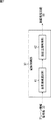
本発明の一側面の撮像装置(例えば、図1の撮像装置1)は、フレーム内圧縮の対象とする画像を固定の量のデータに圧縮する撮像装置において、合焦距離が可変であるレンズ(例えば、図4の可変焦点レンズ11)と、光軸を固定として、前記レンズの合焦距離が変わる毎に撮像する撮像手段(例えば、図4のCMOSイメージセンサ12)と、前記撮像手段により撮像された複数の画像から合焦領域を検出する検出手段(例えば、図4の画像信号処理回路18)と、前記検出手段により検出された合焦領域の中から、所定の数の合焦領域を選択する選択手段(例えば、図7の合焦領域選択部41)と、フレーム内圧縮の対象とする画像の領域のうち、前記選択手段により選択された合焦領域に対応する領域に対して、他の領域よりも多い割合のデータを割り振って圧縮を行う圧縮手段(例えば、図7の動画圧縮制御部42)とを備える。
An imaging apparatus according to one aspect of the present invention (for example, the
本発明の一側面の撮像方法またはプログラムは、光軸を固定として、レンズの合焦距離が変わる毎に撮像し、撮像した複数の画像から合焦領域を検出し、検出した合焦領域の中から、所定の数の合焦領域を選択し、フレーム内圧縮の対象とする画像の領域のうち、選択した合焦領域に対応する領域に対して、他の領域よりも多い割合のデータを割り振って圧縮を行うステップ(例えば、図13のステップS22)を含む。 According to an imaging method or program of one aspect of the present invention, an optical axis is fixed, an image is captured every time a focusing distance of a lens is changed, a focusing area is detected from a plurality of captured images, and a focus area is detected. A predetermined number of in-focus areas are selected, and among the areas of the image to be subjected to intra-frame compression, a larger proportion of data than the other areas is allocated to the area corresponding to the selected in-focus area. And a step of performing compression (for example, step S22 in FIG. 13).
以下、本発明の実施の形態について図を参照して説明する。 Hereinafter, embodiments of the present invention will be described with reference to the drawings.
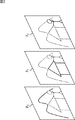
図1は、本発明の一実施形態に係る撮像装置1による撮像の様子を示す図である。
FIG. 1 is a diagram illustrating a state of imaging by an
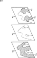
撮像装置1は例えばデジタルビデオカメラであり、合焦距離が可変であるレンズが設けられている。図1に示されるように、撮像装置1に近いものから順に、人物、建物、山などの風景が撮像範囲に存在する場合、撮像装置1は、人物に合焦させた画像、建物に合焦させた画像、風景に合焦させた画像などをそれぞれ撮像することができる。
The
図1の例においては、撮像装置1から距離D1だけ離れた位置に人物が存在し、距離D2だけ離れた位置に建物が存在し、距離D3だけ離れた位置に風景が存在する。図1の一点鎖線Lはレンズの光軸を表す。
In the example of FIG. 1, there is a person in a position away from the
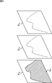
図2は、合焦距離を変えて撮像した画像の例を示す図である。 FIG. 2 is a diagram illustrating an example of an image captured by changing the in-focus distance.
撮像装置1に設けられるレンズの被写界深度は比較的浅く、合焦距離を距離D1として人物に合焦させて撮像した画像である画像P1には建物と風景がピントがあっていない状態で写り、合焦距離を距離D2として建物に合焦させて撮像した画像である画像P2には人物と風景がピントがあっていない状態で写る。また、合焦距離を距離D3として風景に合焦させて撮像した画像である画像P3には人物と建物がピントがあっていない状態で写る。
The depth of field of the lens provided in the
図2において、実線で示される被写体はピントがあっている状態であることを表し、点線で示される被写体はピントがあっていない状態であることを表す。 In FIG. 2, a subject indicated by a solid line indicates that the subject is in focus, and a subject indicated by a dotted line indicates that the subject is not in focus.
撮像装置1においては、例えば、記録開始ボタンがユーザにより押されることに応じて記録デバイスに記録する画像の撮像を開始する直前に、光軸をほぼ固定として合焦距離を所定の間隔で変えながら複数の画像を撮像し、撮像したそれぞれの画像内の合焦領域(ピントがあっている領域)を検出することが行われる。
In the
合焦領域の検出に用いる画像の撮像は、例えば、合焦距離を最も短くした状態から開始され、最も長くした無限遠の状態になるまでの間、合焦距離の可変範囲の全範囲において所定の間隔で連続して行われる。画像内の合焦領域の検出は、画像のコントラストを抽出するなどの方法によって行われる。 Imaging of an image used for detection of the in-focus area starts from a state in which the in-focus distance is the shortest, for example, and is predetermined in the entire range of the variable range of the in-focus distance until the longest infinite state is reached. It is performed continuously at intervals. The in-focus area in the image is detected by a method such as extracting the contrast of the image.
図1に示されるように、撮像装置1から距離D1だけ離れた位置に人物が存在し、距離D2だけ離れた位置に建物が存在し、距離D3だけ離れた位置に風景が存在する場合、合焦距離を距離D1として撮像して得られた画像P1には人物が合焦した状態で写っているから、画像P1からは、図3の右側に示されるように、人物が写っている領域である領域A1が検出され、領域A1と、合焦距離である距離D1が対応付けて管理される。図3においては、検出される合焦領域が斜線で示されている。
As shown in FIG. 1, there is a person in a position away from the
また、合焦距離を距離D2として撮像して得られた画像P2には建物が合焦した状態で写っているから、画像P2からは、図3の中央に示されるように、建物が写っている領域である領域A2が検出され、領域A2と、合焦距離である距離D2が対応付けて管理される。 Further, the image P 2 obtained by taking the in-focus distance as the distance D 2 is shown in a state where the building is in focus. From the image P 2 , as shown in the center of FIG. is to have detected the area a 2 is an area photographed, the area a 2, the distance D 2 is managed in association is the focusing distance.
合焦距離を距離D3として撮像して得られた画像P3には風景が合焦した状態で写っているから、画像P3からは、図3の左側に示されるように、風景が写っている領域である領域A3が検出され、領域A3と、合焦距離である距離D3が対応付けて管理される。 Since the image P 3 obtained by taking the in-focus distance as the distance D 3 is captured in a state where the landscape is in focus, the landscape is captured from the image P 3 as shown on the left side of FIG. The area A 3 that is the area in which the image is recorded is detected, and the area A 3 and the distance D 3 that is the focus distance are managed in association with each other.
なお、合焦した状態で写っている被写体を含むように、その被写体の領域を若干広げた領域までが合焦領域として検出されるようにしてもよい。 It should be noted that up to an area where the area of the subject is slightly widened so as to include the subject in the focused state may be detected as the in-focus area.
図2、図3においては3フレームの画像だけが示されているが、撮像装置1においては、さらに多くの画像が合焦距離を変えながら撮像される。撮像された画像の中には合焦領域が検出されない画像もある。また、図3においてはそれぞれの画像から1つの合焦領域だけが検出されているが、1フレームの画像から複数の合焦領域が検出されることもある。
2 and 3 show only three-frame images, the
合焦領域と合焦距離の対応付けは、撮像装置1の光軸を垂線とする、撮像範囲内の平面(プレーン)の情報を表すプレーン情報によって撮像装置1により管理される。それぞれのプレーン情報には、合焦領域の画像内の位置、範囲、その合焦領域の検出元になった画像を撮像したときの合焦距離などが含まれる。
The association between the in-focus area and the in-focus distance is managed by the
合焦距離は画像内で合焦している被写体までの距離を表すから、このように、撮像装置1によれば、光軸を固定とし、合焦距離を変えて複数の画像の撮像が行われることによって、撮像範囲に含まれるそれぞれの被写体までの距離を取得することができる。
Since the in-focus distance represents the distance to the in-focus subject in the image, in this way, according to the
合焦距離を変えて可変範囲の全範囲分の画像を撮像することは、例えば、1秒間より短い時間内に高速に行われる。可変範囲の全範囲分の画像を撮像することがそのような短い時間内で行われることにより、合焦距離を変えて行われる1回1回の撮像がさらに短い時間間隔で行われることになり、撮像された画像は光軸をほぼ固定して撮像されたものになる。 Taking an image for the entire range of the variable range by changing the focusing distance is performed at high speed within a time shorter than one second, for example. By capturing an image of the entire range of the variable range within such a short time, one time of imaging performed at different focal distances is performed at a shorter time interval. The captured image is captured with the optical axis substantially fixed.
撮像装置1の撮像素子にはCMOS(Complementary Metal Oxide Semiconductor)イメージセンサが用いられており、高速での撮像が可能となっている。以下、適宜、撮像装置1の光軸を垂線とする撮像範囲内のそれぞれの平面の状態を検出するための撮像といえるから、合焦距離を所定の間隔で変えて可変範囲の全範囲分の画像を撮像することをスキャンフォーカスという。
A CMOS (Complementary Metal Oxide Semiconductor) image sensor is used for the image sensor of the
以上のようにして得られたプレーン情報は、例えば、フレーム内圧縮の対象となる1フレームの画像を圧縮するときに、その画像を構成するそれぞれの領域に割り振るデータの割合を決定するのに用いられる。 The plane information obtained as described above is used, for example, to determine a ratio of data to be allocated to each area constituting the image when compressing an image of one frame to be subjected to intra-frame compression. It is done.
撮像装置1においては、動画の圧縮方式として例えばMPEG方式が採用されている。GOPを構成するIピクチャは、目標とする固定の量のデータになるように、対象とする1フレームの画像をJPEG方式で圧縮することによって生成されるが、その固定の量のデータを、どの領域に重点的に割り振るかがプレーン情報に基づいて決定される。
In the
例えば、スキャンフォーカスによって画像の中央付近に合焦領域が検出された場合、撮像装置1は、その合焦領域において合焦する物体を重要な物体であると判断し、フレーム内圧縮の対象とする1フレームの画像の領域のうち、重要な物体が合焦する合焦領域に対応する領域を構成するマクロブロックに、他の領域を構成するマクロブロックより多い割合のデータを割り振って圧縮し、Iピクチャを生成する。ここで、合焦領域に対応する領域とは、合焦領域の検出元になった画像(スキャンフォーカスによって撮像された画像)と、フレーム内圧縮の対象とする画像を同じ大きさにして較べたときに、合焦領域と同じ位置、同じ範囲の、フレーム内圧縮の対象とする画像の領域をいう。
For example, when an in-focus area is detected near the center of the image by scan focus, the
JPEG方式での圧縮においては、圧縮対象の1フレームの画像がマクロブロックなどの所定の画素数からなる領域に分割され、それぞれの領域に対してDCT(Discrete Cosine Transform)、符号化などの処理が施される。 In JPEG compression, an image of one frame to be compressed is divided into areas of a predetermined number of pixels such as macroblocks, and DCT (Discrete Cosine Transform), encoding, and other processing are performed on each area. Applied.
これにより、撮像装置1は、データの割り振りを最適化することができ、重要な物体を、同じ画像に写る他の物体より精度よく符号化することができる。ユーザは重要な物体を中心に画像を見ると考えられるから、ユーザが感じる見た目の画質を向上させることができることになる。
Thereby, the
以上のようにして撮像を行う撮像装置1の一連の処理についてはフローチャートを参照して後述する。
A series of processing of the
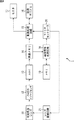
図4は、撮像装置1のハードウエア構成例を示すブロック図である。
FIG. 4 is a block diagram illustrating a hardware configuration example of the
可変焦点レンズ11は、被写体からの光を取り込み、取り込んだ光をCMOSイメージセンサ12に導く。可変焦点レンズ11は複数のレンズから構成され、その位置関係が調整されることによって合焦距離が制御される。合焦距離の制御はレンズ駆動回路21により行われる。
The
CMOSイメージセンサ12は、可変焦点レンズ11を介して入射した光を受光して光電変換を行い、受光量に応じたアナログの画像信号をADC(Analog Digital Converter)13に出力する。
The
ADC13は、CMOSイメージセンサ12から供給された画像信号をA/D変換し、デジタルの画像データを画像メモリ14に出力する。ADC13においては、CMOSイメージセンサ12から供給された画像信号に対して相関二重サンプリング処理、ゲインコントロール処理なども施される。
The ADC 13 A / D converts the image signal supplied from the
画像メモリ14は、ADC13から供給された画像データを記憶する。画像メモリ14に記憶された画像データは動画処理回路15と画像信号処理回路18により適宜読み出される。
The
動画処理回路15は、マイクロコントローラ20による制御に従って動画の記録、再生を行う。
The moving
例えば、動画処理回路15は、動画を記録するとき、画像メモリ14に記憶されている画像データに基づいて所定のフォーマットの動画データを生成し、圧縮した動画データを記録デバイス16に出力する。動画データを圧縮する際、動画処理回路15は、マイクロコントローラ20による制御に従ってそれぞれの領域にデータを割り振り、フレーム内圧縮の対象となる1フレームの画像を圧縮してIピクチャを生成する。また、動画処理回路15は、Iピクチャとの差分や動き情報を符号化するフレーム間圧縮を行うことによって、Pピクチャ、Bピクチャを生成する。
For example, when recording a moving image, the moving
また、動画処理回路15は、動画を再生するとき、記録デバイス16から読み出した動画データを再生して得られた画像信号をモニタ17に出力する。さらに、動画処理回路15は、画像メモリ14に記憶されている画像データに基づいて、取り込み中の画像をモニタ17に表示させることも行う。
Further, the moving
記録デバイス16は、テープ、フラッシュメモリ、ハードディスク、DVD(Digital Versatile Disc)などよりなり、動画処理回路15から供給された、圧縮済みの動画データを記録する。
The
モニタ17はLCD(Liquid Crystal Display)などよりなり、動画処理回路15から供給された画像信号に基づいて取り込み中の画像などを表示する。
The
画像信号処理回路18は、スキャンフォーカスによって撮像された可変範囲の全範囲分の、合焦距離がそれぞれ異なる複数の画像のデータが画像メモリ14に記憶されたとき、画像メモリ14に記憶されている画像データを読み出し、それぞれの画像から合焦領域を検出する。画像信号処理回路18は、合焦領域の画像内の位置、範囲などの、合焦領域に関する情報をマイクロコントローラ20に出力する。
The image
メモリ19は、画像信号処理回路18が処理を行う上で必要なデータを記憶する。
The
マイクロコントローラ20は、所定のプログラムを実行し、動画処理回路15、レンズ駆動回路21を制御して動画の記録、再生などの各種の処理を行う。
The
例えば、マイクロコントローラ20は、レンズ駆動回路21を制御してスキャンフォーカスを行う。また、マイクロコントローラ20は、画像信号処理回路18から供給された合焦領域に関する情報と、合焦領域の検出元になった画像を撮像したときの合焦距離に基づいてプレーン情報を生成する。
For example, the
レンズ駆動回路21は、マイクロコントローラ20による制御に従ってモータを駆動させ、可変焦点レンズ11を構成する各レンズの位置を移動させる。例えば、レンズ駆動回路21は、最も短い距離から最も長い距離まで合焦距離が順次ずれるように各レンズの位置を移動させ、スキャンフォーカスを行う。
The
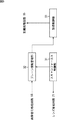
図5は、撮像装置1の機能構成例を示すブロック図である。図5に示す機能部のうちの少なくとも一部は、図4のマイクロコントローラ20により所定のプログラムが実行されることによって実現される。
FIG. 5 is a block diagram illustrating a functional configuration example of the
図5に示されるように、撮像装置1においてはスキャンフォーカス制御部31、プレーン情報管理部32、および記録制御部33が実現される。
As shown in FIG. 5, in the
スキャンフォーカス制御部31は、レンズ駆動回路21を制御してスキャンフォーカスを行う。スキャンフォーカス制御部31は、スキャンフォーカスによってそれぞれの画像を撮像したときの合焦距離の情報をプレーン情報管理部32に出力する。
The scan
図6は、スキャンフォーカスを行うときの可変焦点レンズ11の制御の例を示す図である。
FIG. 6 is a diagram illustrating an example of control of the
図6の横軸は時刻を表し、縦軸は可変焦点レンズ11の合焦距離を表す。図6の例においては、可変焦点レンズ11の合焦距離の可変範囲は距離y0から距離y2(無限遠)までの範囲とされている。距離y1は、スキャンフォーカスを開始する直前、すなわち、スキャンフォーカスが上述したように記録開始ボタンがユーザにより押されることに応じて行われる場合、記録開始ボタンがユーザにより押される直前に、オートフォーカスにより、またはユーザの手動での調整により設定されていた合焦距離である。
The horizontal axis in FIG. 6 represents time, and the vertical axis represents the focusing distance of the
スキャンフォーカス制御部31は、スキャンフォーカスを開始するとき、そのとき設定されている合焦距離である距離y1を記憶し、合焦距離が距離y0になるように可変焦点レンズ11を制御する。スキャンフォーカス制御部31は、合焦距離が距離y0になったとき、合焦距離を距離y2まで所定の間隔で変えながら連続して撮像を行わせる。距離y0から開始されるのではなく、記録開始ボタンがユーザにより押される直前にオートフォーカスなどにより設定されていた合焦距離からスキャンフォーカスが開始されるようにしてもよい。
When the scan focus is started, the scan
図6の例においては、時刻t0から時刻t1までの間にスキャンフォーカスが行われている。時刻t0から時刻t1までの間に示されるそれぞれの矢印のタイミングで1回ずつ撮像が行われ、これにより、合焦距離の異なる複数の画像が1回のスキャンフォーカスによって撮像される。スキャンフォーカス制御部31からプレーン情報管理部32に対しては、それぞれの矢印のタイミングにおける合焦距離の情報が通知される。
In the example of FIG. 6, the scanning focus during the period from the time t 0 to time t 1 is being performed. Imaging is performed once at the timing of each arrow indicated between time t 0 and time t 1 , whereby a plurality of images with different in-focus distances are captured by one scan focus. The scan
スキャンフォーカスによって撮像された画像は、順次、画像メモリ14に記憶される。全ての画像が画像メモリ14に記憶されたとき、画像信号処理回路18においては、それぞれの画像から合焦領域が検出される。
Images picked up by the scan focus are sequentially stored in the
スキャンフォーカスが終わったとき、スキャンフォーカス制御部31は、可変焦点レンズ11の合焦距離を、スキャンフォーカスの開始前に記憶しておいた距離y1に復帰させ、その後、記録デバイス16に記録する画像の撮像を開始する。
When the scan focus is finished, the scan
図6の例においては、時刻t1から時刻t2までの間に、可変焦点レンズ11の合焦距離を距離y1に復帰させることが行われ、その後、記録デバイス16に記録する画像の撮像が行われている。時刻t2以降に撮像された画像に基づいて動画データが生成され、圧縮された後、記録デバイス16に記録される。可変焦点レンズ11の合焦距離を距離y1に復帰させる時刻t1から時刻t2までの間に、合焦領域の検出やフレーム内圧縮でのデータの割り振りなどが決定されるようにしてもよい。
In the example of FIG. 6, the focal distance of the
この例においては、記録デバイス16に記録する画像の撮像を開始する前に1回だけスキャンフォーカスが行われるようになされているが、複数回行われるようにしてもよい。
In this example, the scan focus is performed only once before the imaging of the image to be recorded on the
図5の説明に戻り、プレーン情報管理部32は、画像信号処理回路18から供給された合焦領域に関する情報と、スキャンフォーカス制御部31から供給された合焦距離の情報に基づいてプレーン情報を生成し、生成したプレーン情報を記録制御部33に出力する。
Returning to the description of FIG. 5, the plane
記録制御部33は、プレーン情報管理部32から供給されたプレーン情報を参照して重要な物体が合焦する合焦領域を選択し、選択した合焦領域に対応する領域に多い割合のデータを割り振ってフレーム内圧縮を行わせるなどして、動画処理回路15において行われる動画の記録を制御する。
The
図7は、図5の記録制御部33の構成例を示すブロック図である。
FIG. 7 is a block diagram illustrating a configuration example of the
図7に示されるように、記録制御部33は、合焦領域選択部41、動画圧縮制御部42から構成される。
As shown in FIG. 7, the
合焦領域選択部41は、背景、中間物体、近接物体を、プレーン情報管理部32から供給されたプレーン情報によって表される合焦距離、画像内における合焦領域の占有面積、位置のうちの少なくともいずれかを元に推測する。例えば、合焦領域選択部41は、合焦距離を無限遠として撮像した画像から検出された合焦領域において合焦している物体(被写体)が背景であると推測する。
The focus
また、合焦領域選択部41は、推測した物体の中から重要な物体が合焦する合焦領域を選択し、選択した合焦領域の位置、範囲の情報を動画圧縮制御部42に出力する。
Further, the focus
例えば、合焦領域選択部41は、近距離から中距離にある物体であって、画像の中央付近で合焦している物体がある場合、人物である可能性が高いため、その物体が合焦する合焦領域を選択する。撮像装置1から物体までの距離が近距離から中距離の間にあるかは、プレーン情報によって表される物体までの距離と、あらかじめ設定された、近距離の基準となる閾値、中距離の基準となる閾値に基づいて判断される。
For example, when there is an object that is in the middle distance from a short distance and there is an object that is in focus near the center of the image, the focus
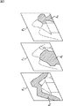
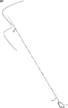
また、図8に示されるように、撮像装置1と風景の間に被写体となるような物体がない状況でスキャンフォーカスが行われた場合、図9に示されるように、合焦距離を無限遠として撮像された画像以外からは合焦領域が検出されないから、このように、無限遠以外に物体がなく、かつ、スキャンフォーカスを行う直前にオートフォーカスなどにより設定されていた合焦距離が無限遠であるときには、合焦領域選択部41は、ユーザが風景を撮像していると判断し、風景(背景)が合焦している合焦領域を選択する。
Further, as shown in FIG. 8, when the scan focus is performed in a situation where there is no object that becomes a subject between the
図9の例においては、スキャンフォーカスによって撮像された画像P11,P12,P13のうちの画像P13から、風景が合焦している領域である領域A11が検出されている。画像P11は、合焦距離が距離D1であるときに撮像された画像であり、画像P12は、合焦距離が距離D2であるときに撮像された画像である。画像P13は、合焦距離が無限遠の距離D3であるときに撮像された画像である。 In the example of FIG. 9, a region A 11 that is a region in which the landscape is in focus is detected from the image P 13 among the images P 11 , P 12 , and P 13 captured by the scan focus. The image P 11 is an image captured when the focus distance is the distance D 1 , and the image P 12 is an image captured when the focus distance is the distance D 2 . Image P 13 is a captured image when the focusing distance is the distance D 3 of infinity.
このように、スキャンフォーカスを行う直前にユーザが手動で設定していた合焦距離、オートフォーカスによって設定されていた合焦距離も考慮され、合焦領域が選択されるようにしてもよい。 As described above, the focus area may be selected in consideration of the focus distance manually set by the user immediately before the scan focus and the focus distance set by the auto focus.
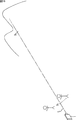
さらに、図10に示されるように、風景を背景として、撮像装置1に近い位置に、光軸を挟んで2人の人物がいるような状況でスキャンフォーカスが行われた場合、図11に示されるように、画像の中央部は無限遠にある物体に合焦し、画像の中央を挟んで左右に分かれる形で、近距離から中距離にある物体に合焦していることが検出される。この場合、合焦領域選択部41は、近距離から中距離にある複数の物体が人物等であると判断し、人物等が合焦している複数の合焦領域を選択する。
Furthermore, as shown in FIG. 10, when scan focus is performed in a situation where there are two persons sandwiching the optical axis at a position close to the
図11の例においては、スキャンフォーカスによって撮像された画像P21,P22,P23のうちの画像P21から、人物が合焦している領域である領域A21と領域A22が検出され、画像P23から、風景が合焦している領域である領域A23が検出されている。画像の中央付近では風景が合焦し、それを挟むように人物が合焦している。 In the example of FIG. 11, the image P 21 of the image P 21, P 22, P 23 captured by the scanning focus, the area A 21 and the area A 22 is an area in which the person is focused is detected from the image P 23, the area a 23 is an area in which scenery is focused is detected. The scenery is in focus near the center of the image, and the person is in focus so as to sandwich it.
このように、1つの画像から検出された複数の合焦領域が選択されるようにしてもよい。 Thus, a plurality of in-focus areas detected from one image may be selected.
図7の説明に戻り、動画圧縮制御部42は、対象の画像がIピクチャとする画像であるとき、その画像の領域のうち、合焦領域選択部41により選択された合焦領域に対応する領域に他の領域より多い割合のデータを割り振ってフレーム内圧縮を行わせるなどして、動画処理回路15において行われる動画の圧縮を制御する。
Returning to the description of FIG. 7, when the target image is an I-picture image, the moving image
これにより、例えば、上述したように人物である可能性が高いと判断された近距離から中距離にある物体が写る領域、無限遠にある物体が写る領域などに、他の領域より多くの割合のデータが割り振られてフレーム内圧縮が行われることになり、それらの重要な物体の画質が向上することになる。特に、撮像範囲の状況がスキャンフォーカスが行われたときとほぼ同じ状況である、動画記録開始直後の部分の画質が向上することになる。 As a result, for example, as described above, the ratio of objects that are determined to be highly likely to be a person to an area at a short to medium distance, an area at which an object at infinity is captured, and the like is larger than other areas. Are allocated to perform intra-frame compression, and the image quality of those important objects is improved. In particular, the image quality of the portion immediately after the start of moving image recording, which is almost the same as that when the scan focus is performed, is improved.
ここで、以上のような構成を有する撮像装置1の処理について説明する。
Here, processing of the
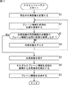
はじめに、図12のフローチャートを参照して、スキャンフォーカスを行う撮像装置1の処理について説明する。
First, processing of the
ステップS1において、スキャンフォーカス制御部31は、現在の合焦距離を記憶する。ここで記憶された合焦距離は、スキャンフォーカスが終わったときに合焦距離を元に戻すときに用いられる。
In step S1, the scan
ステップS2において、CMOSイメージセンサ12は、プレーン情報を生成するのに用いられるプレーン情報生成用の画像を撮像する。このときの合焦距離は、所定の距離にスキャンフォーカス制御部31により調整されている。撮像によって得られた画像データは画像メモリ14に記憶される。
In step S2, the
ステップS3において、スキャンフォーカス制御部31は、合焦距離を変えて可変範囲の全範囲でプレーン情報生成用の画像を撮像したか否かを判定する。
In step S <b> 3, the scan
ステップS3において可変範囲の全範囲でプレーン情報生成用の画像を撮像していないと判定した場合、スキャンフォーカス制御部31は、ステップS4において、レンズ駆動回路21を制御して、合焦距離を例えば長くなる方向に所定の間隔だけずらす。合焦距離の情報はスキャンフォーカス制御部31からプレーン情報管理部32に出力される。その後、ステップS2に戻り、それ以降の処理が繰り返される。
If it is determined in step S3 that an image for generating plane information is not captured in the entire range of the variable range, the scan
一方、ステップS3において最も短い距離から長い距離まで、合焦距離を変えて可変範囲の全範囲でプレーン情報生成用の画像を撮像したと判定した場合、ステップS5において、スキャンフォーカス制御部31は、ステップS1で記憶しておいた合焦距離に可変焦点レンズ11の合焦距離を戻す。
On the other hand, when it is determined in step S3 that the image for generating the plane information is captured in the entire variable range by changing the focusing distance from the shortest distance to the longest distance, in step S5, the scan
ステップS6において、画像信号処理回路18は、スキャンフォーカスによって撮像された画像データを画像メモリ14から読み出し、プレーン情報生成用のそれぞれの画像から合焦領域を検出する。画像信号処理回路18により検出された合焦領域に関する情報は画像信号処理回路18からプレーン情報管理部32に出力される。
In step S6, the image
ステップS7において、プレーン情報管理部32は、画像信号処理回路18から供給された合焦領域に関する情報と、スキャンフォーカス制御部31から供給された合焦距離の情報に基づいてプレーン情報を生成する。その後、処理は終了される。
In step S <b> 7, the plane
以上の処理が、例えば、動画の記録がユーザによって指示されることに応じて行われる。 The above processing is performed, for example, in response to an instruction to record a moving image by the user.
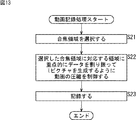
次に、図13のフローチャートを参照して、動画を記録する撮像装置1の処理について説明する。
Next, processing of the
この処理は図12の処理が終了したときに開始される。図12を参照して説明した処理によって生成されたプレーン情報はプレーン情報管理部32から記録制御部33の合焦領域選択部41に供給される。動画の記録に用いるものとしてCMOSイメージセンサ12により撮像された画像は画像メモリ14に記憶される。
This process is started when the process of FIG. The plane information generated by the processing described with reference to FIG. 12 is supplied from the plane
ステップS21において、合焦領域選択部41は、プレーン情報管理部32から供給されたプレーン情報を参照して重要な物体が合焦している合焦領域を選択し、選択した合焦領域の位置、範囲の情報を動画圧縮制御部42に出力する。
In step S21, the focus
ステップS22において、動画圧縮制御部42は、対象の画像がIピクチャとする画像であるとき、合焦領域選択部41により選択された合焦領域に対応する領域に他の領域より重点的に多い割合のデータを割り振ってフレーム内圧縮を行わせ、Iピクチャを生成させるなどして、動画処理回路15において行われる動画の圧縮を制御する。
In step S22, when the target image is an I-picture image, the moving image
ステップS23において、動画処理回路15は、画像メモリ14に記憶されている画像データに基づいて動画データを生成し、圧縮した動画データを記録デバイス16に記録させる。動画データを圧縮する際、動画処理回路15は、動画圧縮制御部42による制御に従ってそれぞれの領域にデータを割り振り、フレーム内圧縮を行うことによってIピクチャを生成する。また、動画処理回路15は、フレーム間圧縮を行うことによって、Pピクチャ、Bピクチャを生成する。動画の記録を終了することがユーザにより指示されたとき、処理は終了される。
In step S <b> 23, the moving
以上においては、スキャンフォーカスによって撮像された画像のうちの1つの画像から検出された合焦領域が選択されるものとしたが、それぞれ異なる画像から検出された合焦領域が選択されるようにしてもよい。 In the above description, the focus area detected from one of the images picked up by the scan focus is selected. However, the focus area detected from each different image is selected. Also good.
例えば、図10に示される人物の一方は近くの位置にいて、他方は少し離れた位置にいる場合、それらの人物はそれぞれ合焦距離の異なる画像において合焦することになるが、このとき、双方が合焦している合焦領域が選択されることにより、2人の人物を精度よく圧縮することが可能となる。 For example, if one of the persons shown in FIG. 10 is in a nearby position and the other is in a slightly separated position, those persons will be in focus in images with different in-focus distances. By selecting an in-focus area where both are in focus, it becomes possible to compress two persons with high accuracy.
また、以上においては、基本的に、位置、面積に基づいて合焦領域が選択されるものとしたが、撮像装置1に風景モード、ポートレートモードなどの各種の撮像モードが用意されている場合、設定されている撮像モードをも考慮して合焦領域が選択されるようにしてもよい。
In the above description, the focus area is basically selected based on the position and area. However, when the
例えば、風景モードが設定されている場合には、合焦距離を無限遠として撮像された画像から検出された合焦領域が選択される。 For example, when the landscape mode is set, a focus area detected from an image captured with the focus distance set to infinity is selected.
また、被写体の人物が画像の中央付近に入るように構図を選択して撮像することが多いため、ポートレートモードが設定されている場合には、画像の中央付近にある合焦領域が選択される。顔検出と組み合わされ、撮像された画像のうちの顔が写っているとして検出された領域を含む合焦領域が、人物が合焦している領域として選択されるようにしてもよい。 In addition, since the subject is often selected and imaged so that the person in the subject enters the vicinity of the center of the image, when the portrait mode is set, the in-focus area near the center of the image is selected. The An in-focus area including an area detected as a face in a captured image combined with face detection may be selected as an area in which a person is in focus.
以上においては、記録開始ボタンが押されることに応じてスキャンフォーカスが行われるものとしたが、記録開始ボタンにユーザの指が触れたことが検出されることに応じてスキャンフォーカスが行われるようにしてもよい。ユーザの指が触れたか否かは、例えば、記録開始ボタンに設けられる静電センサによって検出される。 In the above description, the scan focus is performed in response to the recording start button being pressed. However, the scan focus is performed in response to the detection of the user's finger touching the recording start button. May be. Whether or not the user's finger has touched is detected by, for example, an electrostatic sensor provided on the recording start button.
これにより、記録開始ボタンが押されることに応じてスキャンフォーカスが行われる場合に較べて、ユーザが記録開始ボタンを押したときと実際に動画の記録が開始されるときに遅延が発生してしまうのを防ぐことができる。 This causes a delay when the user presses the recording start button and when the recording of the moving image actually starts, compared to when the scan focus is performed in response to the recording start button being pressed. Can be prevented.
また、以上においては、可変範囲の全範囲分の画像の撮像が終わってから、それぞれの画像から合焦領域が検出されるものとしたが、合焦距離を変えて1フレームの画像の撮像が行われる毎に、撮像された画像を対象として合焦領域が検出されるようにしてもよい。 In the above description, the in-focus area is detected from each image after the image of the entire range of the variable range is finished. However, the image of one frame can be imaged by changing the in-focus distance. Each time it is performed, the in-focus area may be detected for the captured image.
この場合、CMOSイメージセンサ12はX-Yアドレス型の撮像素子であり、所定の画素の画素値を表す信号だけを出力するといったことが可能であるから、1回のスキャンフォーカスにおいて行う複数回の撮像のうちの2回目以降の撮像においては、既に合焦領域として検出された領域に対応する画素の信号を取り込まずに、合焦領域としてまだ検出されていない領域に対応する画素の信号だけを取り込むといったような撮像がCMOSイメージセンサ12により行われるようにしてもよい。
In this case, the
例えば、図3の画像P1乃至P3がその順番で撮像される場合、画像P2の撮像時には、その前に撮像された画像P1から検出された領域A1に対応する画素の信号は取り込まれず、画像P3の撮像時には、その前に撮像された画像P1から検出された領域A1に対応する画素と、画像P2から検出された領域A2に対応する画素の信号は取り込まれない。 For example, when the images P 1 to P 3 in FIG. 3 are captured in that order, when the image P 2 is captured, the signal of the pixel corresponding to the area A 1 detected from the previously captured image P 1 is When the image P 3 is not captured, the signals of the pixels corresponding to the area A 1 detected from the previously captured image P 1 and the pixels corresponding to the area A 2 detected from the image P 2 are captured. I can't.
これにより、取り込みの対象となる画素の信号の数を減らすことができるから、スキャンフォーカスにかかる時間を短縮することができる。 As a result, the number of signals of pixels to be captured can be reduced, so that the time required for scan focus can be shortened.
以上においては、撮像装置1がデジタルビデオカメラであるものとしたが、デジタルスチルカメラにおいて以上のようなスキャンフォーカスや、静止画の圧縮時のデータの割り振りの制御が行われるようにしてもよい。
In the above description, the
上述した一連の処理は、ハードウエアにより実行することもできるし、ソフトウエアにより実行することもできる。一連の処理をソフトウエアにより実行する場合には、そのソフトウエアを構成するプログラムが、専用のハードウエアに組み込まれているコンピュータ、または、各種のプログラムをインストールすることで、各種の機能を実行することが可能な機器に、プログラム記録媒体からインストールされる。 The series of processes described above can be executed by hardware or can be executed by software. When a series of processing is executed by software, a program constituting the software executes various functions by installing a computer incorporated in dedicated hardware or various programs. It is installed from a program recording medium into a device capable of processing.
上述した処理を実行させるプログラムは、本明細書で説明する順序に沿って時系列に処理が行われるプログラムであっても良いし、並列に、あるいは呼び出しが行われたとき等の必要なタイミングで処理が行われるプログラムであっても良い。 The program that executes the processing described above may be a program that is processed in time series in the order described in this specification, or in parallel or at a necessary timing such as when a call is made. It may be a program for processing.
本発明の実施の形態は、上述した実施の形態に限定されるものではなく、本発明の要旨を逸脱しない範囲において種々の変更が可能である。 The embodiments of the present invention are not limited to the above-described embodiments, and various modifications can be made without departing from the scope of the present invention.
1 撮像装置, 11 可変焦点レンズ, 12 CMOSイメージセンサ, 15 動画処理回路, 18 画像信号処理回路, 20 マイクロコントローラ, 21 レンズ駆動回路, 31 スキャンフォーカス制御部, 32 プレーン情報管理部, 33 記録制御部, 41 合焦領域選択部, 42 動画圧縮制御部
DESCRIPTION OF
Claims (9)
合焦距離が可変であるレンズと、
光軸を固定として、前記レンズの合焦距離が変わる毎に撮像する撮像手段と、
前記撮像手段により撮像された複数の画像から合焦領域を検出する検出手段と、
前記検出手段により検出された合焦領域の中から、所定の数の合焦領域を選択する選択手段と、
フレーム内圧縮の対象とする画像の領域のうち、前記選択手段により選択された合焦領域に対応する領域に対して、他の領域よりも多い割合のデータを割り振って圧縮を行う圧縮手段と
を備える撮像装置。 In an imaging device that compresses an image to be subjected to intra-frame compression into a fixed amount of data,
A lens whose focus distance is variable;
An imaging means for taking an image every time the focusing distance of the lens changes with the optical axis fixed,
Detecting means for detecting a focus area from a plurality of images picked up by the image pickup means;
A selection means for selecting a predetermined number of focus areas from the focus areas detected by the detection means;
Compression means for allocating and compressing an area corresponding to the in-focus area selected by the selection means in the image area to be subjected to intra-frame compression by assigning a larger proportion of data than other areas; An imaging apparatus provided.
請求項1に記載の撮像装置。 2. The imaging according to claim 1, wherein the selection unit selects the predetermined number of focusing regions based on at least one of a position and an area in an image from the focusing regions detected by the detection unit. apparatus.
請求項1に記載の撮像装置。 The imaging apparatus according to claim 1, wherein the selection unit selects the predetermined number of focus areas based on a focus distance when an image that is a detection source of the focus area is captured.
請求項1に記載の撮像装置。 The imaging device according to claim 1, wherein the selection unit selects a plurality of focusing areas detected from one image or a plurality of focusing areas detected from different images.
前記圧縮手段は、前記記録デバイスに記録する画像のうちのフレーム内圧縮の対象とする画像の圧縮を、前記選択手段により選択された合焦領域に対応する領域に対して他の領域よりも多い割合のデータを割り振って行う
請求項1に記載の撮像装置。 The imaging means performs imaging of an image to be recorded on a recording device after imaging of an image used for detection of a focus area,
The compression unit compresses an image to be subjected to intra-frame compression among the images to be recorded on the recording device with respect to a region corresponding to the in-focus region selected by the selection unit, as compared with other regions. The imaging apparatus according to claim 1, wherein the ratio data is allocated.
請求項1に記載の撮像装置。 The imaging apparatus according to claim 1, wherein the imaging unit captures an image every time a focusing distance of the lens changes in the entire range of the variable range.
請求項1に記載の撮像装置。 The imaging apparatus according to claim 1, wherein the imaging unit is a CMOS image sensor.
光軸を固定として、前記レンズの合焦距離が変わる毎に撮像し、
撮像した複数の画像から合焦領域を検出し、
検出した合焦領域の中から、所定の数の合焦領域を選択し、
フレーム内圧縮の対象とする画像の領域のうち、選択した合焦領域に対応する領域に対して、他の領域よりも多い割合のデータを割り振って圧縮を行う
ステップを含む撮像方法。 In an imaging method of an imaging apparatus including a lens with a variable focal distance, which compresses an image to be subjected to intra-frame compression into a fixed amount of data,
When the optical axis is fixed and the focusing distance of the lens changes,
A focus area is detected from a plurality of captured images,
Select a predetermined number of focus areas from the detected focus areas,
An image capturing method including a step of allocating and compressing an area corresponding to a selected in-focus area in an image area to be subjected to intra-frame compression by assigning a larger proportion of data than other areas.
光軸を固定として、前記レンズの合焦距離が変わる毎に撮像し、
撮像した複数の画像から合焦領域を検出し、
検出した合焦領域の中から、所定の数の合焦領域を選択し、
フレーム内圧縮の対象とする画像の領域のうち、選択した合焦領域に対応する領域に対して、他の領域よりも多い割合のデータを割り振って圧縮を行う
ステップを含むプログラム。 In a program for causing a computer to execute processing of an imaging apparatus including a lens having a variable focusing distance, which compresses an image to be subjected to intra-frame compression into a fixed amount of data.
When the optical axis is fixed and the focusing distance of the lens changes,
A focus area is detected from a plurality of captured images,
Select a predetermined number of focus areas from the detected focus areas,
A program including a step of allocating and compressing an area corresponding to a selected in-focus area in an image area to be subjected to intra-frame compression by assigning a larger proportion of data than other areas.
Priority Applications (1)
| Application Number | Priority Date | Filing Date | Title |
|---|---|---|---|
| JP2007033600A JP2008199378A (en) | 2007-02-14 | 2007-02-14 | Imaging apparatus, imaging method, and program |
Applications Claiming Priority (1)
| Application Number | Priority Date | Filing Date | Title |
|---|---|---|---|
| JP2007033600A JP2008199378A (en) | 2007-02-14 | 2007-02-14 | Imaging apparatus, imaging method, and program |
Publications (1)
| Publication Number | Publication Date |
|---|---|
| JP2008199378A true JP2008199378A (en) | 2008-08-28 |
Family
ID=39757927
Family Applications (1)
| Application Number | Title | Priority Date | Filing Date |
|---|---|---|---|
| JP2007033600A Pending JP2008199378A (en) | 2007-02-14 | 2007-02-14 | Imaging apparatus, imaging method, and program |
Country Status (1)
| Country | Link |
|---|---|
| JP (1) | JP2008199378A (en) |
Citations (3)
| Publication number | Priority date | Publication date | Assignee | Title |
|---|---|---|---|---|
| JPH11261797A (en) * | 1998-03-12 | 1999-09-24 | Fuji Photo Film Co Ltd | Image processing method |
| JP2003348532A (en) * | 2002-05-24 | 2003-12-05 | Canon Inc | Imaging apparatus |
| JP2005027076A (en) * | 2003-07-03 | 2005-01-27 | Nikon Corp | Electronic camera |
-
2007
- 2007-02-14 JP JP2007033600A patent/JP2008199378A/en active Pending
Patent Citations (3)
| Publication number | Priority date | Publication date | Assignee | Title |
|---|---|---|---|---|
| JPH11261797A (en) * | 1998-03-12 | 1999-09-24 | Fuji Photo Film Co Ltd | Image processing method |
| JP2003348532A (en) * | 2002-05-24 | 2003-12-05 | Canon Inc | Imaging apparatus |
| JP2005027076A (en) * | 2003-07-03 | 2005-01-27 | Nikon Corp | Electronic camera |
Similar Documents
| Publication | Publication Date | Title |
|---|---|---|
| JP4599080B2 (en) | Image encoding method, imaging apparatus, and computer program | |
| US10234653B2 (en) | Imaging device with focus lens stopped at each of focus positions during video capturing | |
| JP4525561B2 (en) | Imaging apparatus, image processing method, and program | |
| US20060028579A1 (en) | Image pickup apparatus, method of controlling image pickup and program | |
| JP4441882B2 (en) | Imaging device, display control method, program | |
| JP4416462B2 (en) | Autofocus method and autofocus camera | |
| TW200925756A (en) | Image capture device | |
| CN101064775A (en) | Camera and shooting control method therefor | |
| CN101047822B (en) | Thumbnail generating device and imaging device | |
| US9456143B2 (en) | Image capture controlling device, image capture controlling method, and program | |
| JP6083162B2 (en) | Image processing apparatus, imaging apparatus, and image processing program | |
| US8040429B2 (en) | Electronic apparatus having autofocus camera function | |
| US8538247B2 (en) | Image processing apparatus and image processing method | |
| CN101631221B (en) | Video recording apparatus, video recording method, and recording medium | |
| JP2009272921A (en) | Moving image recording apparatus, moving image reproducing apparatus, moving image recording method, moving image reproducing method, and semiconductor integrated circuit | |
| JP2011169993A (en) | Imaging device, method for searching continuous af, control program, storage medium and electronic information apparatus | |
| JP2007266659A (en) | Imaging reproducing apparatus | |
| JP2008199378A (en) | Imaging apparatus, imaging method, and program | |
| JP2008199383A (en) | Imaging apparatus, imaging method, and program | |
| JP2015019243A (en) | Imaging apparatus, and control method therefor and program | |
| JP4281778B2 (en) | Imaging apparatus and captured image recording method | |
| JP6409083B2 (en) | Imaging apparatus, imaging method, and imaging program | |
| JP5219678B2 (en) | Imaging device | |
| JP2008199384A (en) | Imaging apparatus, imaging method, and program | |
| JP4517836B2 (en) | Camera device and continuous shooting control program |
Legal Events
| Date | Code | Title | Description |
|---|---|---|---|
| A621 | Written request for application examination |
Free format text: JAPANESE INTERMEDIATE CODE: A621 Effective date: 20091218 |
|
| A977 | Report on retrieval |
Free format text: JAPANESE INTERMEDIATE CODE: A971007 Effective date: 20110527 |
|
| A131 | Notification of reasons for refusal |
Free format text: JAPANESE INTERMEDIATE CODE: A131 Effective date: 20110531 |
|
| A02 | Decision of refusal |
Free format text: JAPANESE INTERMEDIATE CODE: A02 Effective date: 20111006 |