JP2008201364A - Rear wheel suspension device for bicycle - Google Patents
Rear wheel suspension device for bicycle Download PDFInfo
- Publication number
- JP2008201364A JP2008201364A JP2007042541A JP2007042541A JP2008201364A JP 2008201364 A JP2008201364 A JP 2008201364A JP 2007042541 A JP2007042541 A JP 2007042541A JP 2007042541 A JP2007042541 A JP 2007042541A JP 2008201364 A JP2008201364 A JP 2008201364A
- Authority
- JP
- Japan
- Prior art keywords
- swing arm
- fulcrum
- link
- rear wheel
- bicycle
- Prior art date
- Legal status (The legal status is an assumption and is not a legal conclusion. Google has not performed a legal analysis and makes no representation as to the accuracy of the status listed.)
- Pending
Links
- 239000000725 suspension Substances 0.000 title claims abstract description 22
- 230000035939 shock Effects 0.000 claims abstract description 81
- 239000006096 absorbing agent Substances 0.000 claims abstract description 44
- 230000008859 change Effects 0.000 claims description 4
- 230000005484 gravity Effects 0.000 abstract description 7
- 239000013585 weight reducing agent Substances 0.000 abstract description 2
- 238000002835 absorbance Methods 0.000 abstract 1
- 230000000694 effects Effects 0.000 description 22
- 238000010521 absorption reaction Methods 0.000 description 13
- 230000007246 mechanism Effects 0.000 description 12
- 230000009471 action Effects 0.000 description 6
- 238000004519 manufacturing process Methods 0.000 description 2
- 230000009467 reduction Effects 0.000 description 2
- 238000013459 approach Methods 0.000 description 1
- 238000005452 bending Methods 0.000 description 1
- 230000007423 decrease Effects 0.000 description 1
- 238000010586 diagram Methods 0.000 description 1
- 230000004044 response Effects 0.000 description 1
Images




Landscapes
- Axle Suspensions And Sidecars For Cycles (AREA)
Abstract
Description
本発明は、後輪が受ける路面からの衝撃を効果的に吸収して良好な乗り心地や走行安定
性が得られるようにした自転車の後輪懸架装置に関するものである。
The present invention relates to a bicycle rear wheel suspension system that effectively absorbs an impact from a road surface received by a rear wheel to obtain good riding comfort and running stability.
従来、自転車の後輪の衝撃吸収機構として、図8に示すものがある。同図において、車
体フレーム50は、立パイプ51、ダウンチューブ52および上部パイプ53がほぼ三角
形となる配置で互いに連結されている。後輪55を支持するスイングアーム54は、第1
ないし第3の三つのアーム片54a〜54cをほぼ三角形状の配置で連結されてなり、ピ
ボット軸56を介して車体フレーム50に揺動自在に支持されている。上部パイプ53に
支軸59を介して揺動自在に吊り下げられたリンク60の下端部位には、ダウンチューブ
52に支持されたショクアブソーバー57の作動杆57aの先端部とスイングアーム54
とが、それぞれ支軸61,62を介して揺動自在に連結されている。
Conventionally, there is a shock absorbing mechanism for a rear wheel of a bicycle as shown in FIG. In the figure, a
The third three
Are connected to each other through
前記自転車は、走行中に路面の凹凸により後輪55が上方への衝撃力を受けると、スイ
ングアーム54がピボット軸56を支点として上方へ向け揺動する。これにより、ショッ
クアブソーバー57の作動杆57aがリンク60を介して押圧されることにより、ショッ
クアブソーバー57に内蔵した緩衝機構が作動して、後輪55からの衝撃を吸収する。
In the bicycle, when the
また、他の衝撃吸収機構を備えた自転車として、図8と同様の三角形状に構成された車
体フレームと、V字形状のスイングアームとを備え、車体フレームの立パイプの上端部に
支軸を介して揺動自在に取り付けられたリンク部材が、車体フレームの上部パイプの下面
側に取り付けられたショックアブソーバーの作動杆とバックフォーク部材の自由端との間
にそれぞれ支軸を介して相対揺動自在に連結された構造を備えたものも知られている(特
許文献1参照)。
しかしながら、図8の自転車の衝撃吸収機構では、ショクアブソーバー57の作動杆5
7aに対する作用点である支軸61が、リンク60の支軸59を中心とする円弧に沿って
変位するのみの単純な移動を行うだけであるから、後輪55の上下動に伴うスイングアー
ム54のピボット軸56を支点とした揺動運動が、ショックアブソーバー57の作動杆5
7aに対し単純で一義的な特性でしか作用しない。すなわち、スイングアームの揺動角に
対するショックアブソーバー57のリヤクッションストロークとの関係は、直線状に変化
する一定の特性に固定されてしまう。
However, in the shock absorbing mechanism of the bicycle shown in FIG.
Since the
It only works with simple and unambiguous characteristics for 7a. That is, the relationship between the swing angle of the swing arm and the rear cushion stroke of the
一方、特許文献1に記載の衝撃吸収機構は、V字形状のスイングアーム上側先端部を立
パイプに揺動自在に支持された三角形状のリンクに設けた複数の軸穴から選択した一つに
取り付けるようになっているので、走行路面の状況に対応してスイングアームの衝撃吸収
のためのストローク範囲(後輪移動量)を選択することはできるが、ショックアブソーバ
ーの作動杆に対する作用点が、三角形状のリンクの揺動に伴う円弧に沿って変位するのみ
の単純な移動しか行えない点において、図8の構造と同じであるため、やはり、スイング
アームの揺動角に対するショックアブソーバーの特性が一定に固定されてしまう。
On the other hand, the shock absorbing mechanism described in
また、図8の自転車では、ショックアブソーバー57およびリンク60が車体フレーム
50の比較的上方箇所に配置されるので、車体の重心位置が高くなる。この点は特許文献
1に記載の自転車においても同じである。
Further, in the bicycle of FIG. 8, the
さらに、図8の自転車では、リンク60と共にリンク機構を構成するスイングアーム5
4が第1ないし第3アーム片54a〜54cという多くの部材で構成されているとともに
、リンク60が上部パイプ53に支持されているのに伴って前記各アーム片54a〜54
cの形状が大きくなるため、スイングアーム54の重量が増大し、自転車の軽量化を妨げ
る。この点は特許文献1に記載の自転車においても同様である。
Further, in the bicycle shown in FIG. 8, the swing arm 5 that constitutes a link mechanism together with the
4 includes a plurality of members, ie, first to
Since the shape of c increases, the weight of the
本発明は、前記従来の課題に鑑みてなされたもので、後輪のショックアブソーバーの特
性を適宜設定することができ、しかも、重心位置を低く設定でき、かつ小型軽量化が実現
される自転車の後輪懸架装置を提供することを目的としている。
The present invention has been made in view of the above-described conventional problems, and it is possible to appropriately set the characteristics of the shock absorber of the rear wheel, and to set the position of the center of gravity low, and to realize a reduction in size and weight. The object is to provide a rear wheel suspension.
前記目的を達成するために、本発明に係る自転車の後輪懸架装置は、ステアリング軸を
支持するヘッドパイプ、シートを支持する立パイプおよび後方へ向かって下方に傾斜し前
記両パイプを連結するダウンチューブを有する車体フレームと、前記車体フレームに揺動
自在に支持され後輪を支持するスイングアームと、前記ダウンチューブに支持されたショ
ックアブソーバーと、前記ショックアブソーバーの作動杆の先端部と前記スイングアーム
との間にそれぞれ第1支点および第2支点を介して相対揺動自在に連結されたリンクと、
前記リンクと前記車体フレームとの間にそれぞれ第3支点および第4支点を介して相対揺
動自在に連結されたロッドとを備え、前記第3支点が第1支点と第2支点との間に位置し
ている。
In order to achieve the object, a bicycle rear wheel suspension according to the present invention includes a head pipe that supports a steering shaft, a vertical pipe that supports a seat, and a down-tilt that is inclined downward and connects the pipes. A body frame having a tube, a swing arm supported swingably on the body frame and supporting a rear wheel, a shock absorber supported by the down tube, a tip end portion of an operating rod of the shock absorber, and the swing arm A link connected to each other through a first fulcrum and a second fulcrum, respectively,
A rod connected between the link and the vehicle body frame via a third fulcrum and a fourth fulcrum, respectively, so as to be relatively swingable, and the third fulcrum is between the first fulcrum and the second fulcrum. positioned.
この構成によれば、走行時に後輪が走行路面の凹凸により跳ね上げられてスイングアー
ムが上方へ揺動すると、そのスイングアームに第2支点を介して連結されたリンクが前方
へ移動し、ショックアブソーバーの作動杆を押し込むことにより、後輪が受けた衝撃がシ
ョックアブソーバーにより吸収される。このとき、リンクに第3支点を介して連結された
ロッドは、リンクの前方への移動時に車体フレーム上の第4支点回りに揺動して、リンク
を案内する。
According to this configuration, when the rear wheel is flipped up by the unevenness of the traveling road surface and the swing arm swings upward during traveling, the link connected to the swing arm via the second fulcrum moves forward, and shock is applied. By pushing the operating rod of the absorber, the shock received by the rear wheel is absorbed by the shock absorber. At this time, the rod connected to the link via the third fulcrum swings around the fourth fulcrum on the body frame when the link moves forward to guide the link.
したがって、リンクには、スイングアームの車体への連結部を揺動中心とした円弧に沿
って変位する第2支点の揺動と、第4支点を揺動中心とした円弧に沿って変位する第3支
点の揺動とが合わさって作用するので、ショックアブソーバーの作動杆に対する作用点で
ある第1支点は、従来の自転車において円弧に沿った単純な移動であったのに対し、前側
が持ち上がる揺動力を受けながら前方へ移動する複雑な運動を行う。そのため、スイング
アームの揺動角とショックアブソーバーのリヤショックストロークとの関係は、従来の自
転車では単に直線状に変化する一義的なものに固定されるのに対し、曲線状に変化する衝
撃吸収特性となるとともに、その衝撃吸収特性は、例えばロッドの長さを変更することな
どにより、種々に可変設定することができる。これにより、自転車の広範囲な用途に対し
て、その各々に適応できる衝撃吸収能力を有するように適宜変更して設定することができ
るので、ユーザーの多様なニーズに対応することができる。また、ショックアブソーバー
、リンクおよびロッドが下方に設けられることから、自転車の重心が下がり、操縦性およ
び走行安定性が向上する。
Therefore, the link includes a swing of the second fulcrum that is displaced along the arc whose center is the swing arm connecting portion to the vehicle body, and a second that is displaced along the arc that is centered on the fourth fulcrum. Since the three fulcrum swings act together, the first fulcrum, which is the point of action for the shock absorber's operating rod, was a simple movement along the arc in the conventional bicycle, whereas the front lifted Perform complex movements that move forward while receiving power. Therefore, the relationship between the swing angle of the swing arm and the rear shock stroke of the shock absorber is fixed to a unique one that changes in a straight line in a conventional bicycle, whereas the shock absorption characteristic that changes in a curve In addition, the shock absorption characteristics can be variably set, for example, by changing the length of the rod. Thereby, since it can change suitably and set so that it may have the shock absorption capability which can adapt to each with respect to the wide use of a bicycle, it can respond to a user's various needs. Further, since the shock absorber, the link and the rod are provided below, the center of gravity of the bicycle is lowered, and the maneuverability and running stability are improved.
本発明において、前記第4支点は前記ダウンチューブまたは前記立パイプのいずれか一
方に択一的に配置することができる。第4支点をダウンチューブに設けた場合には、スイ
ングアームが揺動し始めた初期での衝撃吸収の効きが良く、スイングアームの揺動角が大
きくなるのに伴い衝撃吸収の効きが鈍く、かつ直線的に増大するので、小さな凹凸が多く
比較的なだらかな路面を走行する用途に適用することにより、機敏性に富んだダイレクト
な操縦性能が得られ、乗り心地が向上する。一方、第4支点を立パイプに配置した場合に
は、スイングアームが揺動し始めた初期での衝撃吸収の効きが鈍く、スイングアームの揺
動角が大きくなるのに伴い衝撃吸収の効きがほぼ直線的に急激に増大し、この衝撃吸収の
効きの増大がスイングアームの揺動角が最大となるまで継続するので、比較的大きな凹凸
が存在する路面を走行する用途に適用することにより、後輪が受ける衝撃を効果的に吸収
して障害を乗り越え易くなり、かつ車体フレームの耐久性および走行性能が向上する。
In the present invention, the fourth fulcrum can be alternatively arranged on either the down tube or the standing pipe. When the fourth fulcrum is provided on the down tube, the effect of absorbing the shock is good at the initial stage when the swing arm starts to swing, and the effect of absorbing the shock becomes dull as the swing angle of the swing arm increases. In addition, since it increases linearly, it is possible to obtain direct maneuvering performance rich in agility and improve riding comfort by applying it to a comparatively gentle road surface with many small irregularities. On the other hand, when the fourth fulcrum is arranged on the vertical pipe, the impact absorbing effect at the initial stage when the swing arm begins to swing is slow, and the impact absorbing effect is increased as the swing arm swing angle increases. Since it increases substantially linearly and this shock absorption effect continues until the swing arm swing angle is maximized, by applying it to a road surface with relatively large irregularities, It effectively absorbs the impact received by the rear wheels to easily overcome obstacles, and improves the durability and running performance of the body frame.
本発明において、好ましくは、前記スイングアームは前部が下方へ曲がったL字状の側
面形状を有し、前端部が車体フレームに揺動自在に支持され、前記L字状の角部に前記第
2支点が配置されている。この構成によれば、スイングアームの揺動中心となる前端部か
ら角部までの距離を適宜大きくとることにより、スイングアームの揺動による角部の第2
支点の移動量、つまりリンクの移動量を大きくとって、ショックアブソーバーの効きを適
切に設定できる。また、スイングアームのL字状の角部に第2支点を配置しているから、
リンクの位置が低くなるので、第1支点を介してリンクに連結されるショックアブソーバ
ーをダウンチューブの下方位置に配置することができる結果、車体の重心位置が低くなっ
て、操縦性能および走行安定性が向上する。さらに、スイングアームはL字状の側面形状
を有するアーム部材で構成できるので、従来の自転車のように形状の大きな三つのアーム
片を組み合わせたスイングアームと比較して、構造が簡素化および小型化され、これに伴
って軽量化されるので、自転車全体の軽量化と製造コストの軽減とを実現することができ
る。
In the present invention, preferably, the swing arm has an L-shaped side shape with a front portion bent downward, a front end portion is swingably supported by a vehicle body frame, and the L-shaped corner portion A second fulcrum is arranged. According to this configuration, by appropriately increasing the distance from the front end portion serving as the swing center of the swing arm to the corner portion, the second corner portion due to swing of the swing arm is obtained.
The effect of the shock absorber can be set appropriately by increasing the movement amount of the fulcrum, that is, the movement amount of the link. Moreover, since the 2nd fulcrum is arrange | positioned at the L-shaped corner | angular part of a swing arm,
Since the position of the link is lowered, the shock absorber connected to the link via the first fulcrum can be arranged at the lower position of the down tube. As a result, the position of the center of gravity of the vehicle body is lowered, and the steering performance and the running stability are reduced. Will improve. Furthermore, since the swing arm can be composed of an arm member having an L-shaped side surface shape, the structure is simplified and miniaturized compared to a swing arm that combines three large arm pieces like a conventional bicycle. Since the weight is reduced accordingly, the weight of the entire bicycle can be reduced and the manufacturing cost can be reduced.
本発明において、好ましくは、前記リンク上の第3支点の位置が可変に設定されている
。この構成によれば、第3支点の位置をリンクの前方寄りに設定した場合には、スイング
アームが揺動し始めた初期において衝撃吸収の効きが鈍く、スイングアームの揺動角が大
きくなるのに伴い衝撃吸収の効きがほぼ直線的に増大する特性が得られる。一方、第3支
点の位置をリンクの後方寄りに設定した場合には、スイングアームが揺動し始めた初期か
ら衝撃吸収の効きが比較的良く、スイングアームの揺動角が大きくなるのに伴い衝撃吸収
の効きがほぼ直線的に増大していく特性が得られる。したがって、用途に応じて第3支点
の位置を適宜選択して設定することにより、良好な衝撃吸収性能を得ることができる。
In the present invention, preferably, the position of the third fulcrum on the link is variably set. According to this configuration, when the position of the third fulcrum is set closer to the front side of the link, the effect of absorbing the shock is slow at the initial stage when the swing arm starts to swing, and the swing angle of the swing arm increases. As a result, a characteristic that the effect of shock absorption increases almost linearly is obtained. On the other hand, when the position of the third fulcrum is set closer to the rear of the link, the effect of absorbing shock is relatively good from the beginning when the swing arm starts to swing, and as the swing angle of the swing arm increases. The characteristic that the effect of shock absorption increases almost linearly is obtained. Therefore, good shock absorbing performance can be obtained by appropriately selecting and setting the position of the third fulcrum according to the application.
本発明において、好ましくは、前記スイングアーム上の第2支点の位置が、スイングア
ームの揺動中心からの距離を変化させるように、可変に設定されている。この構成によれ
ば、スイングアームの揺動角に対するスイングアームの揺動中心から第2支点までの距離
を変更することにより、スイングアームの揺動によるリンクの移動量を変化させて、ショ
ックアブソーバーの効きを調整することができる。
In the present invention, preferably, the position of the second fulcrum on the swing arm is variably set so as to change the distance from the swing center of the swing arm. According to this configuration, by changing the distance from the swing arm swing center to the second fulcrum with respect to the swing angle of the swing arm, the amount of movement of the link due to swing of the swing arm is changed, and the shock absorber Effectiveness can be adjusted.
本発明の自転車の後輪懸架装置は、ショックアブソーバーとスイングアームとを連結す
るリンクが、スイングアームの車体への連結部を揺動中心とした円弧に沿って変位する第
2支点の揺動と、第4支点を揺動中心とした円弧に沿って変位する第3支点の揺動とを合
わせて、前方斜め上方へ向かう複雑な系路に沿って移動するので、スイングアームの揺動
角とショックアブソーバーのリヤショックストロークとの関係が、曲線状に変化する衝撃
吸収特性となり、その衝撃吸収特性を種々に可変設定することができる。これにより、自
転車の広範囲な用途に適応できる衝撃吸収能力を有するように適宜変更して設定すること
ができ、ユーザーの多様なニーズに対応することができる。
According to the bicycle rear wheel suspension device of the present invention, the link that connects the shock absorber and the swing arm is swinging at the second fulcrum where the link is displaced along an arc whose center is the connecting portion of the swing arm to the vehicle body. In addition to the swing of the third fulcrum that is displaced along the arc with the fourth fulcrum as the swing center, it moves along a complicated system path that is obliquely forward and upward. The relationship between the shock absorber and the rear shock stroke becomes a shock absorbing characteristic that changes in a curved line, and the shock absorbing characteristic can be variably set. Thereby, it can change suitably and set so that it may have the impact absorption capability which can adapt to the wide range use of a bicycle, and it can respond to a user's various needs.
以下、本発明の好ましい実施形態について図面を参照しながら詳細に説明する。 Hereinafter, preferred embodiments of the present invention will be described in detail with reference to the drawings.
図1は本発明の第1実施形態に係る後輪懸架装置を備えた自転車を示す概略右側面図で
ある。この自転車は、ステアリング軸2を揺動自在に挿通させて支持するヘッドパイプ3
と、シート4を上端で支持する立パイプ7と、後方へ向かって下方に傾斜しヘッドパイプ
3と立パイプ7の下部とを連結するダウンチューブ8と、ヘッドパイプ3と立パイプ7の
上部とを連結する上部パイプ9とにより、ほぼ三角形状の車体フレーム1が構成されてい
る。ステアリング軸2の下部にフロントフォーク12が連結されており、このフロントフ
ォーク12の下端部に前輪13が支持されている。ステアリング軸2の上部にハンドル1
4が取り付けられている。
FIG. 1 is a schematic right side view showing a bicycle provided with a rear wheel suspension device according to a first embodiment of the present invention. This bicycle has a
A standing
4 is attached.
車体フレーム1のダウンチューブ8と立パイプ7との連結箇所にスイングアームブラケ
ット17が設けられ、このスイングアームブラケット17に、前部が下方へ曲がったL字
状の側面形状を有するスイングアーム18の前端部が、ピボット軸19を介して揺動自在
に支持されている。このスイングアーム18の後端部に後輪20が支持されている。スイ
ングアーム18のほぼL字形状の角部である屈曲部18aに左右一対の連結片23が固着
されている。
A
前記ダウンチューブ8にはショックアブソーバー21が取付軸22を介して揺動自在に
取り付けられている。このショックアブソーバー21の作動杆21aの先端部とスイング
アーム18の角部の連結片23とは、立パイプ7を挟んで左右一対のリンク24により、
それぞれ第1支軸27および第2支軸28の回りに相対揺動自在に連結されている。リン
ク24は長手方向の中央部において下向きに僅かに屈曲した側面形状を有している。なお
、このリンク24の形状は直線状でもよい。
A
The
ダウンチューブ8におけるリンク24の下方位置には、第1取付片29が固着されてお
り、前記リンク24の屈曲箇所(中間部分)と第1取付片29とは、ロッド30により、
それぞれ第3および第4支軸31,32の回りに相対回動自在に連結されている。すなわ
ち、ロッド30は第1取付片29を介してリンク24とダウンチューブ8とを相対揺動自
在に連結しており、リンク24の第3支軸31は第1支軸27と第2支軸28との間に位
置している。これらリンク24およびロッド30によりリンク機構が構成されている。こ
うして、リンク24と作動杆21aおよびスイングアーム18とがそれぞれ、第1支軸2
7および第2支軸28の軸心である第1および第2支点を介して相対揺動自在に設定され
、ロッド30とリンク24およびダウンチューブ8とがそれぞれ、第3支軸31および第
4支軸32の軸心である第3および第4支点を介して相対揺動自在に設定されている。ま
た、立パイプ7には、ロッド30を第1取付片29に代えて連結できる第2取付片33が
固着されている。
A
The third and
7 and the
前記自転車の要部の平面図を示す図2において、スイングアーム18は、屈曲部18a
に対し後方側が後輪20の左右両側に延びる二股形状に形成され、かつ屈曲部18aに対
し前方側がスイングアームブラケット17(図1)の左右両側に延びる二股形状に形成さ
れている。立パイプ7を挟んで左右両側に位置する一対のリンク24は、各々の前端部が
ショックアブソーバー21の作動杆21aに第1支軸27を介して連結され、かつ各々の
後端部がスイングアーム18の連結片23に第2支軸28を介して連結されている。ロッ
ド30は、その後端部が第3支軸31を介して左右一対のリンク24に揺動自在に連結さ
れ、その前端部が第4支軸32を介して左右一対の第1取付片29に揺動自在に連結され
ている。
In FIG. 2, which shows a plan view of the main part of the bicycle, the
On the other hand, the rear side is formed in a bifurcated shape extending on both the left and right sides of the
つぎに、前記後輪懸架装置により衝撃を吸収する作用について説明する。図1の後輪2
0が走行路面の凹凸によって跳ね上げられると、それに伴って、後輪20を支持するスイ
ングアーム18もピボット軸19を支点として上方に揺動する。スイングアーム18の屈
曲部18aの連結片23に連結されたリンク24は、スイングアーム18の揺動角に対応
する距離だけ前方へ押圧されて移動し、このリンク24の中間部に第3支軸31を介して
揺動自在に連結されたロッド30は、リンク24の前方への移動に伴い、第4支軸32を
支点として前方へ揺動する。したがって、リンク24は、揺動するロッド30により、第
4支軸32回りに揺動するように案内される。すなわち、リンク24は、第2支軸28を
支点として前方側が持ち上げられる状態に揺動しながら前方へ移動されることにより、第
1支軸27を介してショックアブソーバー21を、支軸22を支点に持ち上げるように揺
動させながら、その作動杆21aを内部に押し込む。
Next, the action of absorbing an impact by the rear wheel suspension device will be described.
When 0 is flipped up by the unevenness of the traveling road surface, the
リンク24およびロッド30からなるリンク機構が上述した動作を行うことにより、後
輪20が受けた衝撃は、ショックアブソーバー21が有する油圧シリンダおよびコイルス
プリングのような緩衝機構(図示せず)により吸収される。そののち、スイングアーム1
8は、ショックアブソーバー21の油圧シリンダおよびコイルスプリングにより突出する
方向に常時付勢されている作動杆21aの復元力を受けて、元の位置に速やかに戻される
。
When the link mechanism including the
In response to the restoring force of the operating
リンク24には、ピボット軸19を中心とした円弧に沿って変位する第2支軸28の揺
動と、第4支軸32を中心とした円弧に沿って変位する第3支軸31の揺動とが合わさっ
て作用するので、前記リンク機構の作動杆21aに対する作用点である第1支軸27は、
従来の自転車において円弧に沿って移動する単純な運動であったのと異なり、前方斜め上
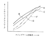
方へ向け移動する運動を行う。そのため、図3に示すように、スイングアーム18の揺動
角とショックアブソーバー21のリヤショックストロークとの関係は、従来の自転車では
直線状に変化する特性に固定されるのに対し、この実施形態では曲線状に変化する特性と
なる。その特性は、ロッド30の長さの変更またはリンク24上の第3支軸31の位置の
変更により、種々に可変設定することができる。
The
Unlike a simple movement that moves along a circular arc in a conventional bicycle, a movement that moves forward and obliquely upward is performed. Therefore, as shown in FIG. 3, the relationship between the swing angle of the
すなわち、図3において、Aは、基準長さ(例えば35mm)のロッド30の一端部を
リンク24における図1に図示した基準部位(第1−第3支軸27,37間の距離が第3
−第2支軸31,28間の距離の0.65倍)に第3支軸31を介して揺動自在に連結し
たときの特性曲線、Bは、基準長さよりも5mm長いロッド30の一端部をリンク24の
基準部位に第3支軸31を介して揺動自在に連結したときの特性曲線、Cは、基準長さよ
りも5mm短いロッド30の一端部をリンク24の基準部位に第3支軸31を介して揺動
自在に連結したときの特性曲線、Dは、基準長さのロッド30の一端部をリンク24の基
準部位に対し前方寄りに5mm変位した位置に第3支軸31を介して揺動自在に連結した
ときの特性曲線、Eは、基準長さのロッド30の一端部をリンク24の基準部位に対し後
方寄りに5mm変位した位置に第3支軸31を介して揺動自在に連結したときの特性曲線
をそれぞれ示す。
That is, in FIG. 3, A is a reference portion (first to
-Characteristic curve when B is slidably connected via the
前記AおよびEの特性曲線が得られるように設定した場合には、スイングアームが揺動
し始めた初期から衝撃吸収の効きが比較的良く、スイングアームの揺動角が大きくなるの
に伴い衝撃吸収の効きが若干鈍くなり、かつほぼ直線的に増大する。また、前記Bの特性
曲線が得られるように設定した場合には、スイングアームの揺動し始めた初期において衝
撃吸収の効きがAおよびEの特性曲線よりも鈍く、スイングアームの揺動角が大きくなる
のに伴い衝撃吸収の効きがAおよびEの特性曲線と同様にほぼ直線的に増大する。一方、
CおよびDの特性曲線が得られるように設定した場合には、スイングアームが揺動し始め
た初期から衝撃吸収の効きがAおよびEの特性曲線と同等程度に良く、スイングアームの
揺動角が大きくなるのに伴い衝撃吸収の効きがほぼ直線的に増大したのち、スイングアー
ムの揺動角が最大に近づく時点からロッド30が押し込まれ難くなって衝撃吸収の効きが
低下する。
When the characteristic curves of A and E are set to be obtained, the impact absorption is relatively good from the beginning when the swing arm starts to swing, and the impact increases as the swing angle of the swing arm increases. The effect of absorption is slightly dull and increases almost linearly. Further, when the characteristic curve B is set to be obtained, the effect of absorbing the shock is duller than the characteristic curves A and E at the beginning of the swing of the swing arm, and the swing angle of the swing arm is As it becomes larger, the effect of shock absorption increases almost linearly like the characteristic curves of A and E. on the other hand,
When the characteristic curves of C and D are set to be obtained, the impact absorbing effect is as good as the characteristic curves of A and E from the beginning when the swing arm starts to swing, and the swing angle of the swing arm As the force increases, the impact absorbing effect increases substantially linearly, and then the
前記自転車では、ロッド30の長さまたはロッド30のリンク24に対する連結位置を
適宜選択して可変することにより、スイングアーム18の揺動角に対するショックアブソ
ーバー21のリヤショックストロークの大きさを、図3のA〜Eの各特性曲線に示したよ
うに、種々の特性に可変して設定できるから、自転車の広範囲な用途に対して、その各々
に適応できる衝撃吸収能力を有するように設定することができ、ユーザーの多様なニーズ
に対応することができる。また、ショックアブソーバー21、リンク24およびロッド3
0が下方に設けられることから、自転車の重心が下がり、操縦性および走行安定性が向上
する。
In the bicycle, the size of the rear shock stroke of the
Since 0 is provided below, the center of gravity of the bicycle is lowered, and maneuverability and running stability are improved.
前記スイングアーム18は前部が下方へ曲がったL字状の側面形状を有し、前端部が車
体フレーム1に揺動自在に支持され、前記L字状の角部18aに第2支軸28が配置され
ているので、スイングアーム18の揺動中心となる前端部から角部までの距離を適宜大き
くとることにより、スイングアーム18の揺動による角部18aの第2支軸28の移動量
、つまりリンク24の移動量を大きくとってショックアブソーバー21の効きを適切に設
定できる。また、スイングアーム18のL字状の角部に第2支軸28を配置しているから
、リンク24の位置が低くなるので、第1支軸27を介してリンク24に連結されるショ
ックアブソーバー21をダウンチューブ8の下方位置に配置することができる結果、車体
の重心位置が低くなって、操縦性能および走行安定性が向上する。
The
また、スイングアーム18はL字状の側面形状を有するアーム部材で構成できるので、
従来の自転車のように形状の大きな三つのアーム片を組み合わせたスイングアームと比較
して、構造の簡素化および小型化が達成されるので、自転車全体の軽量化と製造コストの
軽減とを実現することができる。しかも、上部パイプ9にショックアブソーバー21もリ
ンク機構24,30も支持させないので、この上部パイプ9を削減することもでき、その
ようにした場合には、さらに軽量化およびコスト低減を図ることができる。
Moreover, since the
Compared to a swing arm that combines three large arm pieces like a conventional bicycle, the structure is simplified and downsized, so the entire bicycle is lighter and the manufacturing cost is reduced. be able to. In addition, since neither the
図4は、ロッド30の他端を、図1では第1取付片29を介してダウンチューブ8に連
結したのに代えて、図4の第2取付片33を介して立パイプ7に、第4支軸32の回りに
揺動自在に連結した状態を示している。このように構成したときのスイングアーム18の
揺動角に対するショックアブソーバー21のリヤショックストロークの特性曲線を図5に
示す。この図5のFは、基準長さ(例えば35mm)のロッド30の一端部をリンク24
における図4に図示した中央の基準部位(図1と同一)に第3支軸31を介して揺動自在
に連結したときの特性曲線、Gは、基準長さのロッド30の一端部をリンク24の基準部
位に対し後方寄りに7mm変位した位置に第3支軸31を介して揺動自在に連結したとき
の特性曲線をそれぞれ示す。なお、A〜Cは、図3のA〜Cと同じ特性曲線であって、F
およびGの特性曲線との比較のために合わせて図示している。
4, the other end of the
4 is a characteristic curve when G is connected to the central reference portion (same as FIG. 1) shown in FIG. 4 via the
And for comparison with the characteristic curve of G and G.
リンク機構を図4のように変更した場合には、FおよびGの特性曲線に示すように、ス
イングアームが揺動し始めた初期での衝撃吸収の効きが、図1の場合よりもかなり鈍く、
スイングアームの揺動角が大きくなるのに伴い衝撃吸収の効きがほぼ直線的に急激に増大
し、この衝撃吸収の効きの増大がスイングアーム18の揺動角が最大となるまで継続する
。したがって、比較的大きな凹凸が存在する路面を走行する用途には、後輪20が受ける
衝撃を効果的に吸収できることから、障害を乗り越え易くなり、かつ車体フレーム1の耐
久性および走行性能が向上するので、好適となる。一方、小さな凹凸が存在するだけで比
較的なだらかな路面を走行する用途には、図1のようにロッド30を第1取付片29を介
してダウンチューブ8に連結すれば、AおよびBの特性曲線に示す特性によって、機敏性
に富んだダイレクトな操縦性能が得られ、乗り心地が向上するので、好ましい。
When the link mechanism is changed as shown in FIG. 4, as shown in the characteristic curves of F and G, the impact absorbing effect at the initial stage when the swing arm starts to swing is considerably duller than in the case of FIG. ,
As the swing angle of the swing arm increases, the effect of shock absorption increases substantially linearly, and this increase in the effect of shock absorption continues until the swing angle of the
図6は本発明の第2実施形態に係る後輪懸架装置を備えた自転車の要部を示す概略側面
図である。この実施形態では、リンク24に、ロッド30を連結するための第3支軸31
を挿通させる複数(この実施形態において4つ)の連結孔24a〜24dが、中央部から
後方側に向け一列に配設されている。さらに、スイングアーム18には、屈曲部18aか
らスイングアーム18の揺動中心であるピボット軸19に向けて延びる連結片34が固着
されており、この連結片34に、ピボット軸19から屈曲部18aに向かう方向に一列に
並べて、第2支軸28を挿通させる複数(この実施形態では4つ)の連結孔34a〜34
dが配設されている。
FIG. 6 is a schematic side view showing a main part of a bicycle provided with a rear wheel suspension device according to a second embodiment of the present invention. In this embodiment, the
A plurality (four in this embodiment) of connecting
d is arranged.
この実施形態では、リンク24が有する4つの連結孔24a〜24dのうちから選択し
た一つに第3支軸31を挿通してロッド30を連結できるので、リンク24におけるロッ
ド30の連結位置を容易に変更することができる。また、ロッド30の一端が第4支軸3
2を介して立パイプ7の第2取付片33に連結されている場合においても同様に、ロッド
30の他端を、4つの連結孔24a〜24dのうちから選択した一つに第3支軸31を挿
通してロッド30をリンク24に連結できるので、リンク24におけるロッド30の連結
位置を容易に変更することができる。いずれの場合においても、前側の2つの連結孔24
a,24bにロッド30を連結するときと、後側の2つの連結孔24c,24dにロッド
30を連結するときとで、長さの異なるロッド30を用いる。
In this embodiment, since the
Similarly, in the case where the
The
さらに、リンク24のスイングアーム18への連結位置は、連結片34が有する4つの
連結孔34a〜34dのうちから選択した一つに第2支軸28を挿通することにより、容
易に変更することができる。その場合、スイングアーム18とリンク24との連結部であ
る第2支軸28の位置は、スイングアーム18の揺動中心であるピボット軸19からの距
離が変化するので、ピボット軸19を揺動中心とするスイングアーム18の揺動角に対す
る第2支軸28の移動量が変化し、ピボット軸19からの距離が最も長い連結孔34aを
用いたときに最も大きく、かつピボット軸からの距離が最も短い連結孔34dを用いたと
きに最も小さくなる。したがって、連結孔34aを用いてスイングアーム18とリンク2
4とを連結したときには、ショックアブソーバー21による衝撃吸収の効きが最も良く、
連結孔34dを用いてスイングアーム18とリンク24とを連結したときには、ショック
アブソーバー21による衝撃吸収の効きが最も鈍い。
Furthermore, the connection position of the
4 is connected to the
When the
この実施形態の後輪懸架装置では、第3支軸31または第2支軸28を適宜選択した所
望の連結孔24a〜24d、34a〜34dに挿通して締結したり、あるいは第4支軸3
2を第1取付片29または第2取付片33の何れかに取り付ける簡単な作業を行うだけで
、種々の衝撃吸収特性が容易に得られるから、自転車のユーザーが自転車の走行目的や走
行すべき路面を含む走行条件などに対し最適となる衝撃吸収特性を選択して、自身で容易
に可変設定することができる。第3支軸31用の連結孔24A〜24dと、第2支軸28
用の連結孔34a〜34dとは、いずれか一方のみを用いてもよい。
In the rear-wheel suspension device of this embodiment, the
Since various shock absorption characteristics can be easily obtained simply by performing a simple operation of attaching 2 to the first mounting
Any one of the connection holes 34a to 34d may be used.
図7(a)および(b)は本発明の第3実施形態に係る後輪懸架装置を備えた自転車の
要部を示す概略側面図および平面図である。第2実施形態では、図6の第3支軸31を所
望の連結孔24a〜24dに挿通して締結することで、リンク24の所望位置にロッド3
0を連結するようにしたが、図7の実施形態では、リンク24におけるロッド30の連結
位置をワンタッチ操作で一層容易に変更できるようになっている。すなわち、ロッド30
のリンク24への連結側先端部には第3支軸31が固定されており、左右のリンク24,
24には回転支軸38を介して回転ドラム37が回転自在に支持され、第3支軸31は、
回転ドラム37における回転中心から偏位した部位に設けられた支持孔37aに揺動自在
に嵌合されている。ロッド30の先端部は回転ドラム37の軸方向中央部に設けた切欠部
39に挿入されて第3支軸31に連結されている。したがって、回転用工具を用いて回転
ドラム37を何れかの方向に回転させると、その回転に伴って第3支軸31がリンク24
に対し前後のいずれかの方向に変位されて、リンク24におけるロッド30の連結位置が
変更される。なお、この偏心軸構造は、スイングアーム18とリンク24とを連結する第
2支軸28にも用いることができる。
FIGS. 7A and 7B are a schematic side view and a plan view showing a main part of a bicycle provided with a rear wheel suspension device according to a third embodiment of the present invention. In the second embodiment, the
In the embodiment shown in FIG. 7, the connecting position of the
The
24, a
The
On the other hand, the connecting position of the
1 車体フレーム
2 ステアリング軸
3 ヘッドパイプ
4 シート
7 立パイプ
8 ダウンチューブ
18 スイングアーム
18a 屈曲部(角部)
19 ピボット軸(スイングアームの揺動中心)
20 後輪
21 ショックアブソーバー
21a 作動杆
24 リンク
27 第1支軸(第1支点)
28 第2支軸(第2支点)
30 ロッド
31 第3支軸(第3支点)
32 第4支軸(第4支点)
DESCRIPTION OF
19 Pivot shaft (swing center of swing arm)
20
28 Second spindle (second fulcrum)
30
32 4th support shaft (4th support point)
Claims (6)
って下方に傾斜し前記両パイプを連結するダウンチューブを有する車体フレームと、
前記車体フレームに揺動自在に支持されて後輪を支持するスイングアームと、
前記ダウンチューブに支持されたショックアブソーバーと、
前記ショックアブソーバーの作動杆の先端部と前記スイングアームとの間にそれぞれ第
1支点および第2支点を介して相対揺動自在に連結されたリンクと、
前記リンクと前記車体フレームとの間にそれぞれ第3支点および第4支点を介して相対
揺動自在に連結されたロッドとを備え、
前記第3支点は前記第1支点と前記第2支点との間に位置している自転車の後輪懸架装
置。 A vehicle body frame having a head pipe that supports the steering shaft, a vertical pipe that supports the seat, and a down tube that is inclined downward toward the rear and connects the pipes;
A swing arm that is swingably supported by the body frame and supports a rear wheel;
A shock absorber supported by the down tube;
A link connected between the tip of the operating rod of the shock absorber and the swing arm via a first fulcrum and a second fulcrum, respectively, so as to be relatively swingable;
A rod connected to the link and the vehicle body frame via a third fulcrum and a fourth fulcrum, respectively, so as to be relatively swingable;
The rear wheel suspension device for a bicycle, wherein the third fulcrum is located between the first fulcrum and the second fulcrum.
懸架装置。 The bicycle rear wheel suspension device according to claim 1, wherein the fourth fulcrum is disposed on the down tube.
置。 The bicycle rear wheel suspension device according to claim 1, wherein the fourth fulcrum is disposed on the standing pipe.
L字状の側面形状を有し、前端部が前記車体フレームに揺動自在に支持され、前記L字状
の角部に前記第2支点が配置されている自転車の後輪懸架装置。 4. The swing arm according to claim 1, wherein the swing arm has an L-shaped side shape with a front portion bent downward, and a front end portion is swingably supported by the vehicle body frame. A bicycle rear-wheel suspension device in which the second fulcrum is disposed at a corner of the shape.
されている自転車の後輪懸架装置。 The bicycle rear wheel suspension system according to any one of claims 1 to 4, wherein a position of a third fulcrum on the link is variably set.
スイングアームの揺動中心からの距離を変化させるように、可変に設定されている自転車
の後輪懸架装置。 The position of the second fulcrum on the swing arm according to any one of claims 1 to 5,
A bicycle rear wheel suspension that is variably set to change the distance from the swing center of the swing arm.
Priority Applications (1)
| Application Number | Priority Date | Filing Date | Title |
|---|---|---|---|
| JP2007042541A JP2008201364A (en) | 2007-02-22 | 2007-02-22 | Rear wheel suspension device for bicycle |
Applications Claiming Priority (1)
| Application Number | Priority Date | Filing Date | Title |
|---|---|---|---|
| JP2007042541A JP2008201364A (en) | 2007-02-22 | 2007-02-22 | Rear wheel suspension device for bicycle |
Publications (1)
| Publication Number | Publication Date |
|---|---|
| JP2008201364A true JP2008201364A (en) | 2008-09-04 |
Family
ID=39779282
Family Applications (1)
| Application Number | Title | Priority Date | Filing Date |
|---|---|---|---|
| JP2007042541A Pending JP2008201364A (en) | 2007-02-22 | 2007-02-22 | Rear wheel suspension device for bicycle |
Country Status (1)
| Country | Link |
|---|---|
| JP (1) | JP2008201364A (en) |
Cited By (4)
| Publication number | Priority date | Publication date | Assignee | Title |
|---|---|---|---|---|
| WO2013029928A1 (en) * | 2011-08-30 | 2013-03-07 | Canyon Bicycles Gmbh | Vehicle frame |
| DE102010010317B4 (en) | 2009-03-09 | 2019-07-04 | Specialized Bicycle Components, Inc. | Bicycle frame with articulated linkage mounting arrangement |
| US11738823B2 (en) | 2018-03-30 | 2023-08-29 | Specialized Bicycle Components, Inc. | Bicycle rear suspension |
| US12612129B2 (en) | 2023-07-13 | 2026-04-28 | Specialized Bicycle Components, Inc. | Bicycle rear suspension |
Citations (5)
| Publication number | Priority date | Publication date | Assignee | Title |
|---|---|---|---|---|
| JPS57147979A (en) * | 1981-03-09 | 1982-09-13 | Honda Motor Co Ltd | Suspension system for rear wheel of autobicycle |
| JPS58100885U (en) * | 1981-12-28 | 1983-07-08 | スズキ株式会社 | Motorcycle rear wheel suspension system |
| JPS61113084U (en) * | 1984-12-28 | 1986-07-17 | ||
| JPH06107264A (en) * | 1992-09-28 | 1994-04-19 | Yamaha Motor Co Ltd | Bicycle rear wheel suspension |
| WO2005030564A2 (en) * | 2003-09-25 | 2005-04-07 | David Weagle | Bicycle suspension systems |
-
2007
- 2007-02-22 JP JP2007042541A patent/JP2008201364A/en active Pending
Patent Citations (6)
| Publication number | Priority date | Publication date | Assignee | Title |
|---|---|---|---|---|
| JPS57147979A (en) * | 1981-03-09 | 1982-09-13 | Honda Motor Co Ltd | Suspension system for rear wheel of autobicycle |
| JPS58100885U (en) * | 1981-12-28 | 1983-07-08 | スズキ株式会社 | Motorcycle rear wheel suspension system |
| JPS61113084U (en) * | 1984-12-28 | 1986-07-17 | ||
| JPH06107264A (en) * | 1992-09-28 | 1994-04-19 | Yamaha Motor Co Ltd | Bicycle rear wheel suspension |
| WO2005030564A2 (en) * | 2003-09-25 | 2005-04-07 | David Weagle | Bicycle suspension systems |
| JP2007506618A (en) * | 2003-09-25 | 2007-03-22 | ウィーグル,デイヴィッド | Bicycle suspension system |
Cited By (8)
| Publication number | Priority date | Publication date | Assignee | Title |
|---|---|---|---|---|
| DE102010010317B4 (en) | 2009-03-09 | 2019-07-04 | Specialized Bicycle Components, Inc. | Bicycle frame with articulated linkage mounting arrangement |
| DE102010064685B4 (en) | 2009-03-09 | 2021-09-30 | Specialized Bicycle Components, Inc. | Bicycle frame with articulated linkage mounting arrangement |
| WO2013029928A1 (en) * | 2011-08-30 | 2013-03-07 | Canyon Bicycles Gmbh | Vehicle frame |
| EP2719614A1 (en) * | 2011-08-30 | 2014-04-16 | Canyon Bicycles GmbH | Bicycle frame |
| CN103748002A (en) * | 2011-08-30 | 2014-04-23 | 峡谷自行车有限责任公司 | Vehicle frame |
| US9469369B2 (en) | 2011-08-30 | 2016-10-18 | Canyon Bicycles Gmbh | Vehicle frame |
| US11738823B2 (en) | 2018-03-30 | 2023-08-29 | Specialized Bicycle Components, Inc. | Bicycle rear suspension |
| US12612129B2 (en) | 2023-07-13 | 2026-04-28 | Specialized Bicycle Components, Inc. | Bicycle rear suspension |
Similar Documents
| Publication | Publication Date | Title |
|---|---|---|
| US8033558B2 (en) | Bicycle rear suspension system | |
| EP3074098B1 (en) | An exercise bike | |
| JP5528870B2 (en) | Front two-wheel straddle-type vehicle | |
| TW201210883A (en) | Rear wheel suspension for a vehicle, in particular a bicycle | |
| TW201713544A (en) | A bicycle frame | |
| EP2419320A1 (en) | Improved bicycle rear suspension system | |
| JP4129297B2 (en) | Bicycle rear suspension | |
| JP2008534370A (en) | Motorcycle | |
| JP2008201364A (en) | Rear wheel suspension device for bicycle | |
| US4398741A (en) | Anti-nose-dive apparatus of a motorcycle | |
| TWI809203B (en) | Forecarriage for motor vehicles with two front steered wheels, with a central shock absorber assembly, and motor vehicle comprising said forecarriage | |
| JP2007216732A (en) | Vehicle steering system | |
| JPH09109974A (en) | Frame for bicycle | |
| CN114340991B (en) | Motor vehicle with suspension using a Tchebicheff four-bar linkage | |
| US6598893B2 (en) | Multi-linking, rockered rear suspension system for two-wheeled vehicles | |
| CA2541040A1 (en) | Cushion mounting structure of saddle-ride vehicle | |
| CN114364550B (en) | Motor vehicle having a suspension using a Watt four-bar linkage | |
| TWI839563B (en) | A motor vehicle with a suspension using a roberts four-bar linkage | |
| JP6525427B1 (en) | Bicycle frame | |
| JP6210852B2 (en) | Saddle riding | |
| JPS6111833B2 (en) | ||
| CN112618184A (en) | Steering mechanism and wheelchair | |
| TWM586691U (en) | Coupling mechanism of vehicle body | |
| JP2009269457A (en) | Front wheel suspension | |
| JP3048695U (en) | Bicycle rear frame shock absorber |
Legal Events
| Date | Code | Title | Description |
|---|---|---|---|
| A977 | Report on retrieval |
Free format text: JAPANESE INTERMEDIATE CODE: A971007 Effective date: 20091030 |
|
| A131 | Notification of reasons for refusal |
Free format text: JAPANESE INTERMEDIATE CODE: A131 Effective date: 20091208 |
|
| A02 | Decision of refusal |
Free format text: JAPANESE INTERMEDIATE CODE: A02 Effective date: 20100406 |