JP2008206552A - Display shelf and display shelf system - Google Patents
Display shelf and display shelf system Download PDFInfo
- Publication number
- JP2008206552A JP2008206552A JP2007043505A JP2007043505A JP2008206552A JP 2008206552 A JP2008206552 A JP 2008206552A JP 2007043505 A JP2007043505 A JP 2007043505A JP 2007043505 A JP2007043505 A JP 2007043505A JP 2008206552 A JP2008206552 A JP 2008206552A
- Authority
- JP
- Japan
- Prior art keywords
- projector
- display
- image
- screen
- display shelf
- Prior art date
- Legal status (The legal status is an assumption and is not a legal conclusion. Google has not performed a legal analysis and makes no representation as to the accuracy of the status listed.)
- Pending
Links
Images




Classifications
-
- A—HUMAN NECESSITIES
- A47—FURNITURE; DOMESTIC ARTICLES OR APPLIANCES; COFFEE MILLS; SPICE MILLS; SUCTION CLEANERS IN GENERAL
- A47F—SPECIAL FURNITURE, FITTINGS, OR ACCESSORIES FOR SHOPS, STOREHOUSES, BARS, RESTAURANTS OR THE LIKE; PAYING COUNTERS
- A47F3/00—Show cases or show cabinets
- A47F3/001—Devices for lighting, humidifying, heating, ventilation
-
- A—HUMAN NECESSITIES
- A47—FURNITURE; DOMESTIC ARTICLES OR APPLIANCES; COFFEE MILLS; SPICE MILLS; SUCTION CLEANERS IN GENERAL
- A47F—SPECIAL FURNITURE, FITTINGS, OR ACCESSORIES FOR SHOPS, STOREHOUSES, BARS, RESTAURANTS OR THE LIKE; PAYING COUNTERS
- A47F11/00—Arrangements in shop windows, shop floors or show cases
- A47F11/06—Means for bringing about special optical effects
Landscapes
- Display Racks (AREA)
- Freezers Or Refrigerated Showcases (AREA)
- Devices For Indicating Variable Information By Combining Individual Elements (AREA)
Abstract
【課題】横方向からの観察でも表示を良好に認識することができ、訴求効果が高い陳列棚を提供する。
【解決手段】品物4を載置可能な載置台6a,6b,6cと、載置台6a,6b,6cに隣接して配置され、裏面側からプロジェクタ画像が投影され、表面に情報表示画像が表示される透過型のスクリーン7a,7b,7cと、入力された表示画像データに基づいて前記プロジェクタ画像を投影するプロジェクタ200と、を備える陳列棚システム100において、スクリーン7a,7b,7cを湾曲形成し、側方から視認可能な横向表示部とする。
【選択図】図1An object of the present invention is to provide a display shelf capable of recognizing a display well even by observation from the lateral direction and having a high appeal effect.
[MEANS FOR SOLVING PROBLEMS] A mounting table (6a, 6b, 6c) on which an article (4) can be mounted and a mounting table (6a, 6b, 6c) arranged adjacent to each other, a projector image is projected from the back side, and an information display image is displayed on the surface. Screen 7a, 7b, 7c, and projector 200 for projecting the projector image based on the input display image data, screen 7a, 7b, 7c is curved. The horizontal display unit is visible from the side.
[Selection] Figure 1
Description
本発明は、陳列棚及び陳列棚システムに係り、特に品物を載置可能な載置台と、前記載置台に隣接して配置され、裏面側からプロジェクタ画像が投影され、表面に情報表示画像が表示される透過型のスクリーンと、入力された表示画像データに基づいて前記プロジェクタ画像を投影するプロジェクタと、を備える陳列棚及びこれを使用した陳列棚システムに関する。 The present invention relates to a display shelf and a display shelf system, and in particular, a mounting table on which an article can be mounted, and a projector image that is disposed adjacent to the mounting table, is projected from the back side, and an information display image is displayed on the front surface. The present invention relates to a display shelf including a transmissive screen to be projected and a projector that projects the projector image based on input display image data, and a display shelf system using the display shelf.
従来、品物を陳列する陳列棚は、代表的には小売業の店舗、例えばスーパーマーケットやコンビニエンスストア、ホームセンター、デパート内の各種商品の売場等で広く用いられている。小売業の店舗では、陳列棚に品物としての商品を陳列し、陳列する商品に対応付けて棚札が付けられる。この棚札は、対応付けられる商品の価格やその他の情報を顧客に示すことを目的としている。このような棚札として電子棚札が開発されている(特許文献1、特許文献2参照)。例えば、特許文献1の図6には、例えば液晶パネルや有機ELパネル等によって棚札表示を行う陳列棚が開示されている。 2. Description of the Related Art Conventionally, display shelves for displaying items are typically widely used in retail stores such as supermarkets, convenience stores, home centers, and department stores. In a retail store, merchandise as goods is displayed on a display shelf, and a shelf label is attached in association with the merchandise to be displayed. This shelf label is intended to show the customer the price of the associated product and other information. An electronic shelf label has been developed as such a shelf label (see Patent Document 1 and Patent Document 2). For example, FIG. 6 of Patent Document 1 discloses a display shelf that performs shelf label display using, for example, a liquid crystal panel or an organic EL panel.
小売業の店舗で用いられる陳列棚は、商品を陳列し、棚札や電子棚札を用いて陳列した商品の価格やその他の情報を示すことを主要な用途としている。これに対して、陳列棚に陳列した商品を顧客に注目させ、より多くの購買につなげる手法として、POP広告(Point of Purchase)という手法が従来多く用いられている。特許文献3には、陳列棚の天壁にプロジェクタとこのプロジェクタからの投影画像を透過投影するスクリーンとを設けた陳列棚(特許文献3ではショーケース)が開示されている。
Display shelves used in retail stores mainly display products and display the price and other information of products displayed using shelf labels and electronic shelf labels. On the other hand, a technique called POP advertisement (Point of Purchase) has been widely used as a technique for paying attention to products displayed on display shelves and leading to more purchases.
このような技術を採用することで、通常は紙などの記録媒体に印刷されるPOP広告の取付作業を行うことなく、スクリーンに透過投影するプロジェクタ画像により、陳列棚に陳列された商品の展示効果を高めることができる。 By adopting such a technique, the display effect of the products displayed on the display shelves by the projector image that is transmitted and projected onto the screen without performing the operation of attaching the POP advertisement that is normally printed on a recording medium such as paper. Can be increased.
ところで、特許文献1に開示されている電子棚札や、特許文献2に開示されている電子棚ラベルシステム、及び、特許文献3に開示されている陳列棚では、値段や広告の表示が平面として構成された表示面に表される。このため、正面から表示面の表示は見やすいものとなっているが、液晶表示装置の視野角が限られることもあり、表示面に対して角度をもった横位置からは、表示面の表示像は見にくいものとならざるを得ない。そのため、横方向からの観察者からは表示面の表示は見にくいものとなっている。このような横方向からの観察者は、陳列棚に横方向から近接してくるものであり、陳列棚の配置個所によっては多く存在する。
By the way, in the electronic shelf label disclosed in Patent Document 1, the electronic shelf label system disclosed in
そこで、本発明は、横方向からの観察でも表示を良好に認識することができ、訴求効果が高い陳列棚を提供することを課題とする。 Therefore, an object of the present invention is to provide a display shelf that can recognize a display satisfactorily even by observation from the lateral direction and has a high appeal effect.
本発明において上記の課題を解決するための手段は、品物を載置可能な載置台と、入力された表示画像データに基づいてプロジェクタ画像を投影するプロジェクタを配置可能なプロジェクタ配置部と、前記載置台に隣接して配置され、裏面側から前記プロジェクタ画像が投影され、表面に情報表示画像が表示されると共に、少なくとも一部において前記情報表示画像が載置台の正面方向に対して横方向に傾斜して表示される横向表示部を備えるスクリーンと、を備えることを特徴とする陳列棚である。 Means for solving the above-described problems in the present invention include a mounting table on which an article can be mounted, a projector arrangement unit capable of arranging a projector that projects a projector image based on input display image data, and the above description Arranged adjacent to the mounting table, the projector image is projected from the back side, an information display image is displayed on the front surface, and at least in part, the information display image is inclined laterally with respect to the front direction of the mounting table A display shelf including a horizontal display unit displayed as a display shelf.
本発明によれば、陳列棚のスクリーンにはその中間部が両端部より前方に位置し、横方向に向け傾斜して配置された横向表示部が設けられているから、スクリーンの表示を横方向からでも視認しやすくすることができ、訴求効果を高めることができる。 According to the present invention, the screen of the display shelf is provided with the horizontal display portion that is positioned in front of the both end portions and inclined in the horizontal direction. It is possible to make it easy to see even from the outside, and the appeal effect can be enhanced.
以下本発明に係る陳列棚の実施の形態例を図1乃至図7に基づいて説明する。なお、本実施の形態は、陳列棚をスーパーマーケットに配置した陳列棚システムを例として説明する。 Embodiments of a display shelf according to the present invention will be described below with reference to FIGS. In the present embodiment, a display shelf system in which display shelves are arranged in a supermarket will be described as an example.
図1は陳列棚システムを示す模式図、図2は陳列棚の構成を示す図1中のA−A線に相当する断面模式図、図3は陳列棚の構成を示す図2中のB−B線に相当する断面模式図である。 1 is a schematic diagram showing a display shelf system, FIG. 2 is a schematic cross-sectional view corresponding to the AA line in FIG. 1 showing the configuration of the display shelf, and FIG. 3 is a B- in FIG. 2 showing the configuration of the display shelf. It is a cross-sectional schematic diagram equivalent to a B line.
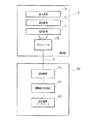
陳列棚システム100は、店舗内に設置される陳列棚10と、陳列棚10の内部に設置されるプロジェクタ200と、バックヤード310に配置される陳列棚10の表示制御部であるコンピュータ300とから構成されている。プロジェクタ200とコンピュータ300とは、回線101を介して接続されている。
The
陳列棚10は、一対の側板3,3と、この側板3,3に挟まれる天井板2、奥板12、底板13及び下部前板14によって構成される。
The
天井板2は、陳列棚10の最上部で一対の側板3に挟まれ、陳列棚10の上部を覆うように水平となるように固定されている。天井板2は、矩形状の後方部2aと、その前縁を弧状をする前方部2bとからなり、両端部より中央部が前方に突出する略半円形状をなしている。
The
奥板12は、陳列棚10の背面に、下辺を床面11に接し、上辺を天井板2に接続して、前記側板3,3に挟まれて鉛直となるように固定されている。下部前板14は、陳列棚10の前面の下方に、一対の側板3に挟まれて下辺を床面11に接して、鉛直となるように固定されている。
The
そして、陳列棚10は、前記側板3,3の間に形成され、プロジェクタ200が配置される直方体形状の下部空間部19と、この下部空間部19の上方奥側に配置され、前記プロジェクタ200のプロジェクタ画像が垂直方向に上方に向け投影される立方体形状の画像投影空間部17とを備えて形成されている。
The
また、陳列棚10には、品物4を載置可能な3段の載置台6a,6b,6c、即ち上段載置台6a、中段載置台6b、下段載置台6cが配置されている。各載置台6a,6b,6cはそれぞれ前記側板3,3に挟まれて水平となるように固定され、各載置台6a,6b,6cの上部に商品4を載置可能な載置空間5a,5b,5cが形成される。
The
ここで、上段載置台6a及び中段載置台6bは、前記天井板2と同様に両端部より中央部が前方に突出する半円形状に形成されており、それらの前縁は弧状をなしている。また、下段載置台6cは矩形をなし、その前縁は前記奥板12と平行となるよう構成され下部前板14の上縁と接続されている。
Here, the upper
陳列棚10には、前記画像投影空間部17の前方に位置し、画像投影空間部17から前側に突出配置された上段スクリーン7a、中段スクリーン7b、下段スクリーン7cからなる3段のスクリーン7a,7b,7cを備えている。上段スクリーン7aは天井板2の弧状の前縁から垂下され、中段スクリーン7bは上段載置台6aの弧状の前縁から垂下され、更に、下段スクリーン7cは中段載置台6bから垂下されている。そして、各スクリーン7a,7b,7cはその両端部を側板3,3に接しており、側板3,3に接する両端部より中央部が前方に突出する弧状をなしている。このため、各スクリーン7a,7b,7cは正対方向に対して横方向に向け傾斜して配置される横向表示部を構成することになる。
The
ここで、上段スクリーン7a、中段スクリーン7b、下段スクリーン7cは、例えばポリカーボネート等の合成樹脂で形成され、裏面側から投影されるプロジェクタ画像を表面に透過投影可能な透過型のものである。
Here, the
本例では、天井板2、載置台6a、及び、載置台6bの画像投影空間部17からの突出寸法D1,D2,D3は、図2に示すように、D1<D2<D3となるようにしている。なお、載置台6b及び載置台6cの突出量は同じ値としている。
In this example, the projecting dimensions D1, D2, and D3 of the
各載置空間5a,5b,5cの上方には、天板8a,8b,8cが配置される他、載置空間5a,5b,5cの奥側には奥板9a,9b,9cが配置されている。そして、前記天板8aと天井板2との間には、プロジェクタ200からの投射光が通過する投影空間10aが、天板8bと載置台6aとの間には投影空間10bが、天板8cと載置台6bとの間には投影空間10cが形成されている。
In addition to the
陳列棚10の下部空間部19内には、プロジェクタ200が配置されるプロジェクタ設置部19aが設けられている。プロジェクタ設置部19aに配置されるプロジェクタ200は、レンズ201から前記上段スクリーン7a、中段スクリーン7b、下段スクリーン7cに向けて例えば液晶表示パネル202に一画面で構成されたプロジェクタ画像を投射する、液晶プロジェクタが採用される。
プロジェクタ200は、回線101を介してバックヤード310に設置されたコンピュータ300と接続されている。
In the
The
前記画像投影空間部17には、プロジェクタ200から水平方向に投影されるプロジェクタ画像を上方に向け反射する主反射鏡21と、主反射鏡21で反射されたプロジェクタ画像を前記3つの投影空間10a,10b,10cに向け反射する3つの投影鏡24a,24b,24cが配置されている。主反射鏡21及び投影鏡24a,24b,24cはいずれも、プロジェクタ画像を反射する鏡面を一方の面に備える平面鏡として構成される。
The image
主反射鏡21は、陳列棚10の画像投影空間部17の下部でプロジェクタ200のレンズ201の高さに配置され、プロジェクタ200から陳列棚10の後方に向けて水平方向に投射されるプロジェクタ画像を、上方向に偏向させる向きに配置されている。
The main reflecting
投影鏡24a,24b,24cは、陳列棚10の画像投影空間部17で主反射鏡21の上方に、上段スクリーン7a、中段スクリーン7b、下段スクリーン7cに対応付けて配置されている。これらの投影鏡24a,24b,24cはその上端を対応するスクリーン7a,7b,7cの上縁部の高さ位置に合わせ、プロジェクタ画像をスクリーン7a,7b,7cの裏面側に投影する向きに配置されている。即ち、投影鏡24aはプロジェクタ画像を上段スクリーン7aの裏面側に投影する向きに、投影鏡24bはプロジェクタ画像を中段スクリーン7bの裏面側に投影する向きに、投影鏡24cはプロジェクタ画像を下段スクリーン7cの裏面側に投影する向きに、それぞれ配置される。そして、投影鏡24a,24b,24cはそれぞれ、陳列棚10の前後方向に位置を違えて、主反射鏡21によって偏向され下方から入射されるプロジェクタ画像を互いに遮らない位置関係に配置されている。
The projection mirrors 24a, 24b, and 24c are disposed in the
以上のような位置関係に配置された主反射鏡21及び投影鏡24a,24b,24cで構成される光学系によって、プロジェクタ200から投影されたプロジェクタ画像は、個々のスクリーン7a,7b,7cの裏面側に分割して導かれる。そして、陳列棚10では、以下のような画像が表示される。
Projector images projected from the
即ち、陳列棚システム100では、コンピュータ300で作製された表示画像データをプロジェクタ200に回線101を経由して送信され、プロジェクタ200内に配置された画像メモリに格納され、その内容がプロジェクタ画像として投影される。
That is, in the
プロジェクタ200は、コンピュータ300から送信された画像データを受信し、受信した画像データに基づいて一画面で構成されたプロジェクタ画像を生成し、生成したプロジェクタ画像をスクリーン7a,7b,7cに投影する。
The
コンピュータ300は、処理ソフトウエアを実行し、キーボード303、マウス304の操作により、プロジェクタ200が投影する画像を作成する。この画像は、ディスプレイ302に表示され、表示画像はそのままプロジェクタ200が投影する画像となる。
The
本例では、プロジェクタ200の液晶表示パネル202からの投影光がスクリーン7a,7b,7cに合焦した像を結像するように位置が決定されている。ここで、各スクリーン7a,7b,7cは、湾曲形成されているから、各スクリーン7a,7b,7cに正確に合焦した像は結像されないが、プロジェクタ200の焦点深度が深いため、スクリーン7a,7b,7cにはプロジェクタ像が視認可能な状態で表示される。
In this example, the position is determined so that projected light from the liquid
コンピュータ300は、その外観態様として、本体タワー301、ディスプレイ302、キーボード303、及びマウス等のポインティングデバイス304を備えて構成され、プロジェクタ200が投射するプロジェクタ画像の画像データを管理する。
The
このような、陳列棚10では、以下のような画像が表示される。即ち、陳列棚システム100では、コンピュータ300で作製された表示画像データをプロジェクタ200にネットワーク101を経由して送信され、プロジェクタ200内に配置された画像メモリに格納され、その内容がプロジェクタ画像として投影される。
In such a
以下、表示画像例について説明する。コンピュータ300では、画像処理ソフトウエアを実行し、キーボード303、ポインティングデバイス304の操作により、プロジェクタ200が投影する画像を作成する。この画像は、ディスプレイ302に表示され、表示画像はそのままプロジェクタ200が投影する画像となる。
Hereinafter, display image examples will be described. The
そして、このような操作により作成された画像が、各スクリーン7a,7b,7cに投影される。
Then, images created by such operations are projected on the
図4は陳列棚のスクリーンに表示される画像を示す模式図である。この例では、最上段のスクリーン7aには、「××××」の表示31、「○○○○」の表示32、「△△△△」の表示33が投影される。同様に中段のスクリーン7bには「△△△△」の表示34、及び「□□□□」の表示35、「××××」の表示36、更に、下段のスクリーン7cには、「××××」の表示37及び「○○○○」の表示38、「○○○○」の表示39が投影される。
FIG. 4 is a schematic diagram showing an image displayed on the screen of the display shelf. In this example, a
これらの表示は、例えば商品名及び商品の価格等の商品情報とすることができる。また、商品のPOP広告を表示することができる。 These displays can be, for example, product information such as product names and product prices. In addition, a POP advertisement for a product can be displayed.
次に陳列棚のスクリーンへの表示制御について説明する。図5は陳列棚システムの電気的構成を示すブロック図、図6は陳列棚システムの構成を示す機能ブロック図である。 Next, display control on the display shelf screen will be described. FIG. 5 is a block diagram showing the electrical configuration of the display shelf system, and FIG. 6 is a functional block diagram showing the configuration of the display shelf system.
コンピュータ300は、プロジェクタ200の表示制御部410として作動する。コンピュータ300は、図5に示すように、CPU411と、固定データを格納したROM412と、処理プログラムを一時的に格納すると共にワークエリアとなるRAM413と、OSや処理プログラム、データベース等を格納したハードディスクドライブ(HDD)414をバスライン415で接続して構成している。また、表示制御部410は、CD-ROMドライブ416、前記ディスプレイ302、キーボード303、マウス304を図示しないインタフェースを介してバスライン415に接続して備えている。更に、バスライン415には、通信装置417を接続しており、通信装置417には、前記プロジェクタ200が回線101を介して接続されている。
The
本例では、コンピュータ300はCPU411で、処理プログラムを実行することにより、表示制御部410の作用をなす。また、HDD414には表示画像データベース420が格納されている。
In this example, the
表示画像データベース420には、上段スクリーン7a、中段スクリーン7b、及び下段スクリーン7cに表示する画像データが格納されている。これらの画像は陳列される商品4の名称価格等の商品情報である。これらの画像データは、コンピュータ300で処理プログラムを実行してディスプレイ302で確認しながらキーボード303及びマウス304を操作して作成することができる他、商品4のメーカが提供するものを採用することができる。
The
これらの構成により、陳列棚10の各スクリーン7a,7b,7cに載置空間5a,5b,5cに配置した商品4の商品情報や、POP広告を表示することができる。
With these configurations, it is possible to display the product information of the
そして、本例に係る陳列棚システム100によれば、陳列棚10のスクリーン7a,7b,7cをその中間部が両端部より前方に位置する横向表示部を形成したから、図7に示すように、陳列棚10の正面に位置する観者41の他、陳列棚10の横側に位置する観者42,43からもスクリーンの表示を視認しやすくすることができ、訴求効果を高めることができる
なお、上記例では、陳列棚システムにおいて、コンピュータをバックヤードに配置するものとして説明したが、コンピュータを陳列棚の内部に設けることができる。この場合、陳列棚に内蔵したコンピュータには画像データを内蔵させておくことができ、コンピュータによる表示画面を外部のコントロール用のコンピュータ等の装置で制御することができる。
And according to the
また、上記実施例では、上中下の3段すべての載置台に配置される3つのスクリーンをすべて湾曲した形状のものとしたが、一部のスクリーン、例えば最上のスクリーン、あるいは最上及び中段のスクリーンを湾曲した形状のものとし、他のスクリーンを平面形状のものとしてもよい。 Further, in the above embodiment, all the three screens arranged on the upper, middle, and lower stages of the stage are curved, but some screens, for example, the uppermost screen, or the uppermost and middle stage The screen may have a curved shape, and the other screen may have a planar shape.
そして、前記例では、スクリーンの形状は、スクリーン全体として弧状をなすものとしたが、スクリーンの一部に横向表示部を形成するようにしてもよい。 In the above example, the screen has an arc shape as a whole, but a horizontal display portion may be formed on a part of the screen.
図8は他の例に係る陳列棚を示すものである。図8(a)〜(g)には、陳列棚の1段のスクリーンを模式的に示している。また、本例では陳列棚は、スクリーンの形状以外は、上述した陳列棚と同様の構成を備えるものである。 FIG. 8 shows a display shelf according to another example. FIGS. 8A to 8G schematically show a one-stage screen of a display shelf. In this example, the display shelf has the same configuration as the display shelf described above except for the shape of the screen.
図8(a)に示した例では、スクリーン111の一端側に突出部121aを形成し、突出部121aの両側に横向表示部としてスクリーン111a,111bを配置している。また、本例ではスクリーン111cは正面を向く平面状のものとしている。本例では、スクリーン111cに表示された画像を正面から良好に視認することができる他、スクリーン111a,111bに表示されたプロジェクタ画像は側方(図中矢印で示した)から良好に視認でき、訴求力を良好なものとすることができる。
In the example shown in FIG. 8A, a protruding portion 121a is formed on one end side of the
図8(b)に示した例では、スクリーン112の中央部に突出部122を形成し、突出表示部122の両側に横向表示部としてスクリーン112b,112dを配置している。また、スクリーン112の両端部に配置したスクリーン112a,112e及び突出部122の頂部に配置したスクリーン112cは正面を向く平面状のものとしている。本例では、スクリーン112a,112c,112eに表示された画像を正面から良好に視認することができる他、スクリーン112b,112dに表示されたプロジェクタ画像は側方(図中矢印で示した)から良好に視認でき、訴求力を良好なものとすることができる。
In the example shown in FIG. 8B, a protrusion 122 is formed at the center of the
図8(c)に示した例では、スクリーン113の中央部に突出部123を形成し、突出部123の両側に横向表示部としてスクリーン113a,113bをなだらかな傾きをもって配置している。本例では、スクリーン113a,113bに表示された画像を正面及び側方(図中矢印で示した)から良好に視認でき、訴求力を良好なものとすることができる。
In the example shown in FIG. 8C, a
図8(d)に示した例では、スクリーン114の両端部に突出部124a,124bを形成し、中央部から突出部124a,124bに向け横向表示部としてスクリーン114a,114bをなだらかな傾きをもって配置している。本例では、スクリーン114a,114bに表示された画像を正面及び側方(図中矢印で示した)から良好に視認でき、訴求力を良好なものとすることができる。
In the example shown in FIG. 8 (d),
図8(e)に示した例では、スクリーン115の両端に突出部125a,125bを形成し、突出部125aの両側に横向表示部としてスクリーン115a,115bを、突出部125bの両側に横向表示部としてスクリーン115d,115eを配置している。また、本例では両突出部125a,125bの間に配置するスクリーン115cは正面を向く平面状のものとしている。本例では、スクリーン115cに表示された画像を正面から良好に視認することができる他、スクリーン115a,115b、115d,115eに表示されたプロジェクタ画像は側方(図中矢印で示した)から良好に視認でき、訴求力を良好なものとすることができる。
In the example shown in FIG. 8E,
図8(f)に示した例では、スクリーン116の両側端部に突出部126a,126bを形成し、突出部126aの内側に横向表示部としてスクリーン116bを、突出部126bの内側に横向表示部としてスクリーン116cを配置している。本例では突出部126aの前側に配置したスクリーン116a、突出部126bの前側に配置したスクリーン116e、両突出表示部126a、126bの間に配置したスクリーン116cは正面を向く平面状のものとしている。本例では、スクリーン116a,116c,116eに表示された画像を正面から良好に視認することができる他、スクリーン116b,116cに表示されたプロジェクタ画像は側方(図中矢印で示した)から良好に視認でき、訴求力を良好なものとすることができる。
In the example shown in FIG. 8 (f),
図8(g)に示した例では、スクリーン117の両端及び中央部に突出部127a,127b,127cを形成し、突出部127aの内側にスクリーン117bを、突出部127bの両側にスクリーン117d,117fを、突出部127cの内側にスクリーン117hを傾斜させて配置している。また、本例では各突出部127a,127b,127cの前側に配置したスクリーン117a、117e、117i、及び、各突出部127a,127b,127cの間に配置するスクリーン117c,スクリーン117gを平面状のものとして形成している。本例では、スクリーン117a,117c,117e,117g,117iに表示された画像を正面から良好に視認することができる他、横向表示部として設けたスクリーン117b,117d、117f,117hに表示されたプロジェクタ画像は側方(図中矢印で示した)から良好に視認でき、訴求力を良好なものとすることができる。
In the example shown in FIG. 8G,
5a,5b,5c…載置空間、6a,6b,6c…載置台、7a,7b,7c…スクリーン(横向表示部)、10…陳列棚、200…プロジェクタ 5a, 5b, 5c ... placement space, 6a, 6b, 6c ... placement table, 7a, 7b, 7c ... screen (horizontal display unit), 10 ... display shelf, 200 ... projector
Claims (7)
入力された表示画像データに基づいてプロジェクタ画像を投影するプロジェクタを配置可能なプロジェクタ配置部と、
前記載置台に隣接して配置され、裏面側から前記プロジェクタ画像が投影され、表面に情報表示画像が表示されると共に、少なくとも一部において前記情報表示画像が載置台の正面方向に対して横方向に傾斜して表示される横向表示部を備えるスクリーンと、
を備えることを特徴とする陳列棚。 A mounting table on which goods can be placed;
A projector placement unit capable of placing a projector that projects a projector image based on input display image data;
Arranged adjacent to the mounting table, the projector image is projected from the back side, and an information display image is displayed on the front surface. A screen provided with a horizontal display unit that is tilted and displayed,
A display shelf comprising:
前記載置台の上段の載置台又は上段に配置される部材に取り付けられて、前記載置台の前方上側に配置され、後方である裏面側から投影された画像を表面側に透過投影可能であり、表面に情報表示画像が表示されると共に、少なくとも一部において前記情報表示画像が載置台の正面方向に対して横方向に傾斜して表示される横向表示部を備える透過型スクリーンと、
一画面で構成されたプロジェクタ画像を投影するプロジェクタが配置されるプロジェク
タ設置部と、
前記複数の載置台の後側に配置され、前記プロジェクタからのプロジェクタ画像を略鉛
直方向に導くよう確保された鉛直投影領域と、
前記鉛直投影領域における前記複数の透過型スクリーンの設置の高さ位置に対応した高
さ位置に配置され、プロジェクタが投影する一画面のプロジェクタ画像の一部をなす分割
プロジェクタ画像を分離すると共に、この分割プロジェクタ画像を略水平方向に向け投影
するように偏向する複数の反射装置と、
各載置台の上側であって前記反射装置と前記透過型スクリーンとの間に配置され、前記各
分割プロジェクタ画像を水平方向に導き前記透過型スクリーンに投射するよう確保された
複数の画像水平投影領域と、を備える陳列棚。 A plurality of mounting tables on which articles can be placed and arranged at different height positions;
Attached to the upper stage mounting table or the member arranged on the upper stage of the previous mounting table, disposed on the front upper side of the previous mounting table, and can be transmissively projected on the front side the image projected from the back side that is the rear, An information display image is displayed on the surface, and at least part of the information display image includes a horizontal display unit that is displayed in a horizontal direction with respect to the front direction of the mounting table;
A projector installation unit in which a projector for projecting a projector image composed of one screen is arranged;
A vertical projection area disposed behind the plurality of mounting tables and secured to guide a projector image from the projector in a substantially vertical direction;
A split projector image that is arranged at a height position corresponding to the height position of the installation of the plurality of transmissive screens in the vertical projection area and forms a part of a one-screen projector image projected by the projector, and A plurality of reflecting devices for deflecting the divided projector images so as to project the images in a substantially horizontal direction;
A plurality of horizontal image projection areas which are arranged between the reflection device and the transmissive screen above each mounting table and secured to guide each divided projector image in a horizontal direction and project it onto the transmissive screen. And a display shelf.
Priority Applications (6)
| Application Number | Priority Date | Filing Date | Title |
|---|---|---|---|
| JP2007043505A JP2008206552A (en) | 2007-02-23 | 2007-02-23 | Display shelf and display shelf system |
| AT08002370T ATE543417T1 (en) | 2007-02-23 | 2008-02-08 | SHELF DISPLAY AND DISPLAY SYSTEM |
| EP08002370A EP1961338B1 (en) | 2007-02-23 | 2008-02-08 | Display shelf and display system |
| US12/070,696 US7954958B2 (en) | 2007-02-23 | 2008-02-20 | Display shelf with a plurality of placing tables |
| CNA2008100740778A CN101248939A (en) | 2007-02-23 | 2008-02-21 | Display racks and display rack systems |
| US13/094,784 US8167436B2 (en) | 2007-02-23 | 2011-04-26 | Display shelf with placing tables and transmission-type screens having projecting parts and laterally-facing displays |
Applications Claiming Priority (1)
| Application Number | Priority Date | Filing Date | Title |
|---|---|---|---|
| JP2007043505A JP2008206552A (en) | 2007-02-23 | 2007-02-23 | Display shelf and display shelf system |
Publications (1)
| Publication Number | Publication Date |
|---|---|
| JP2008206552A true JP2008206552A (en) | 2008-09-11 |
Family
ID=39357666
Family Applications (1)
| Application Number | Title | Priority Date | Filing Date |
|---|---|---|---|
| JP2007043505A Pending JP2008206552A (en) | 2007-02-23 | 2007-02-23 | Display shelf and display shelf system |
Country Status (5)
| Country | Link |
|---|---|
| US (2) | US7954958B2 (en) |
| EP (1) | EP1961338B1 (en) |
| JP (1) | JP2008206552A (en) |
| CN (1) | CN101248939A (en) |
| AT (1) | ATE543417T1 (en) |
Cited By (3)
| Publication number | Priority date | Publication date | Assignee | Title |
|---|---|---|---|---|
| WO2017082637A1 (en) * | 2015-11-12 | 2017-05-18 | 엘지전자 주식회사 | Shelf display module including projector, and display stand including shelf display module |
| KR20170073043A (en) * | 2015-12-18 | 2017-06-28 | 엘지전자 주식회사 | Shelf display module including projector and display stand comprising the same |
| JP2018025620A (en) * | 2016-08-09 | 2018-02-15 | 大日本印刷株式会社 | Transmission screen, video display device |
Families Citing this family (27)
| Publication number | Priority date | Publication date | Assignee | Title |
|---|---|---|---|---|
| JP4913514B2 (en) * | 2006-03-28 | 2012-04-11 | 東芝テック株式会社 | Display shelf and display shelf system |
| JP4321782B2 (en) | 2007-02-09 | 2009-08-26 | 東芝テック株式会社 | Display shelf |
| JP2008206552A (en) * | 2007-02-23 | 2008-09-11 | Toshiba Tec Corp | Display shelf and display shelf system |
| US9060136B1 (en) * | 2010-06-14 | 2015-06-16 | Open Invention Network, Llc | Advanced gameplay system |
| AU2012225443A1 (en) * | 2011-03-08 | 2013-10-31 | T-Ink, Inc. | Intelligent display and fixture system |
| US20130033650A1 (en) * | 2011-08-02 | 2013-02-07 | 3M Innovative Properties Company | Display system and method for projection onto multiple surfaces |
| WO2013103833A1 (en) | 2012-01-06 | 2013-07-11 | Sunrise R&D Holdings, Llc | Display shelf modules with projectors for displaying product information and modular shelving systems comprising the same |
| US9225131B2 (en) | 2012-06-15 | 2015-12-29 | RTC Industries, Incorporated | Low voltage power supply with magnetic connections |
| US9360196B2 (en) | 2012-06-15 | 2016-06-07 | Rtc Industries, Inc. | Low voltage power supply for a merchandise display system |
| US9146029B2 (en) | 2012-06-15 | 2015-09-29 | RTC Industries, Incorporated | Power supply with mechanical connections |
| US9316890B2 (en) * | 2012-08-01 | 2016-04-19 | Ricoh Company, Ltd. | Projector positioning |
| CN103728821B (en) * | 2012-10-12 | 2015-10-28 | 扬明光学股份有限公司 | projection device |
| CN103431688B (en) * | 2013-08-09 | 2016-12-28 | 谢新华 | Inclined bottom plate display rack |
| DE202013104137U1 (en) * | 2013-09-11 | 2013-09-23 | Gesa Form + Funktion Displaybau Gmbh | Goods presentation module with backlight and goods presentation unit |
| US10901548B2 (en) * | 2015-04-07 | 2021-01-26 | Omnivision Technologies, Inc. | Touch screen rear projection display |
| CN107735808A (en) | 2015-05-04 | 2018-02-23 | 日升研发控股有限责任公司 | System and method for controlling a shelf display unit and for graphically presenting information on a shelf display unit |
| CN105832060A (en) * | 2015-12-07 | 2016-08-10 | 江苏海事职业技术学院 | Intelligent display stand used for display of industrially-designed products |
| CN105832061A (en) * | 2015-12-07 | 2016-08-10 | 江苏海事职业技术学院 | Intelligent display system for industrial design |
| EP3305138A1 (en) * | 2016-10-05 | 2018-04-11 | Ariel Haroush | Modular powered secure product display mount |
| AU2019212621B2 (en) | 2018-01-26 | 2021-11-04 | Rtc Industries, Inc. | Low voltage power system for a merchandise display |
| EP3949810A4 (en) * | 2019-04-02 | 2022-05-18 | Panasonic Intellectual Property Management Co., Ltd. | IMAGE DISPLAY DEVICE AND FURNITURE EQUIPPED THEREOF |
| CN111713923A (en) * | 2020-05-20 | 2020-09-29 | 合肥京亿盛精密科技有限公司 | Product display equipment for numerical control machine tool |
| CN111946992A (en) * | 2020-08-24 | 2020-11-17 | 衡阳县石荷岭绿色食品有限公司 | Information display board and display system for food sales |
| CN114494892B (en) * | 2022-04-15 | 2022-07-15 | 广州市玄武无线科技股份有限公司 | Goods shelf commodity display information identification method, device, equipment and storage medium |
| US12502013B2 (en) * | 2022-07-14 | 2025-12-23 | Outform Ltd. | Modular product display system |
| US12446711B2 (en) | 2023-01-31 | 2025-10-21 | Carter-Hoffmann LLC | Heated display cabinet |
| US12022964B1 (en) | 2023-01-31 | 2024-07-02 | Carter-Hoffmann LLC | Heated display cabinet |
Family Cites Families (17)
| Publication number | Priority date | Publication date | Assignee | Title |
|---|---|---|---|---|
| JPH0717608A (en) | 1993-05-06 | 1995-01-20 | Hitachi Ltd | Electronic shelf label system |
| JPH071995A (en) | 1993-06-17 | 1995-01-06 | Mazda Motor Corp | Automatic braking system for vehicles |
| DE69419579T2 (en) * | 1993-10-21 | 2000-08-10 | Kabushiki Kaisha Toshiba, Kawasaki | Multi-screen display device and method for assembling it |
| JPH07231838A (en) | 1994-02-23 | 1995-09-05 | Okashijiyou Kagahan:Kk | Showcase |
| JP3159370B2 (en) * | 1996-05-23 | 2001-04-23 | 鹿島建設株式会社 | Dome type environment simulation method and apparatus |
| JP2001245756A (en) | 2000-03-03 | 2001-09-11 | Sanyo Electric Co Ltd | Showcase |
| DE10101030C2 (en) * | 2001-01-11 | 2003-12-24 | Umdasch Shop Concept Gmbh Amst | Multimedia store building shelf |
| DE202004003242U1 (en) * | 2003-02-28 | 2004-06-03 | Schulte, Wolfgang | Shop display stand with projector for advertising images provides image appearing near shelves and image appearing at distance from them |
| TWM245695U (en) * | 2003-07-14 | 2004-10-01 | Coretronic Corp | Rear projection display apparatus |
| JP2005099888A (en) | 2003-09-22 | 2005-04-14 | Dainippon Printing Co Ltd | Electronic shelf label system |
| US20050168707A1 (en) * | 2004-01-30 | 2005-08-04 | Feldpausch Thomas G. | Convertible projection assembly and method |
| JP4556542B2 (en) | 2004-08-09 | 2010-10-06 | セイコーエプソン株式会社 | Image display device |
| DE202006004645U1 (en) * | 2006-03-23 | 2006-06-08 | Schween, Thomas | Freestanding wall unit for use at trade fairs and exhibitions, at presentations or in sales rooms |
| JP4913514B2 (en) * | 2006-03-28 | 2012-04-11 | 東芝テック株式会社 | Display shelf and display shelf system |
| US7997734B2 (en) * | 2006-12-21 | 2011-08-16 | Toshiba Tec Kabushiki Kaisha | Image display controller for display shelf |
| JP4321782B2 (en) * | 2007-02-09 | 2009-08-26 | 東芝テック株式会社 | Display shelf |
| JP2008206552A (en) * | 2007-02-23 | 2008-09-11 | Toshiba Tec Corp | Display shelf and display shelf system |
-
2007
- 2007-02-23 JP JP2007043505A patent/JP2008206552A/en active Pending
-
2008
- 2008-02-08 AT AT08002370T patent/ATE543417T1/en active
- 2008-02-08 EP EP08002370A patent/EP1961338B1/en not_active Not-in-force
- 2008-02-20 US US12/070,696 patent/US7954958B2/en not_active Expired - Fee Related
- 2008-02-21 CN CNA2008100740778A patent/CN101248939A/en active Pending
-
2011
- 2011-04-26 US US13/094,784 patent/US8167436B2/en not_active Expired - Fee Related
Cited By (4)
| Publication number | Priority date | Publication date | Assignee | Title |
|---|---|---|---|---|
| WO2017082637A1 (en) * | 2015-11-12 | 2017-05-18 | 엘지전자 주식회사 | Shelf display module including projector, and display stand including shelf display module |
| KR20170073043A (en) * | 2015-12-18 | 2017-06-28 | 엘지전자 주식회사 | Shelf display module including projector and display stand comprising the same |
| KR102517612B1 (en) * | 2015-12-18 | 2023-04-03 | 엘지전자 주식회사 | Shelf display module including projector and display stand comprising the same |
| JP2018025620A (en) * | 2016-08-09 | 2018-02-15 | 大日本印刷株式会社 | Transmission screen, video display device |
Also Published As
| Publication number | Publication date |
|---|---|
| US20080204672A1 (en) | 2008-08-28 |
| US7954958B2 (en) | 2011-06-07 |
| ATE543417T1 (en) | 2012-02-15 |
| US8167436B2 (en) | 2012-05-01 |
| EP1961338A1 (en) | 2008-08-27 |
| EP1961338B1 (en) | 2012-02-01 |
| CN101248939A (en) | 2008-08-27 |
| US20110199585A1 (en) | 2011-08-18 |
Similar Documents
| Publication | Publication Date | Title |
|---|---|---|
| JP2008206552A (en) | Display shelf and display shelf system | |
| JP4913514B2 (en) | Display shelf and display shelf system | |
| JP4321782B2 (en) | Display shelf | |
| JP4891219B2 (en) | Image display housing | |
| JP6981002B2 (en) | Display shelves, information processing equipment, programs and display shelf systems | |
| JP4999489B2 (en) | Display shelf | |
| JP5444403B2 (en) | Image projection method and image projection system | |
| JP4877985B2 (en) | Display shelf system | |
| JP2006047890A (en) | Image display device | |
| JP2008173452A (en) | Display shelf image display control device | |
| WO2014085098A1 (en) | On-product projection for digital merchandizing | |
| JP2008194121A (en) | Display shelf | |
| JP2008284168A (en) | Display shelf | |
| JP4877986B2 (en) | Display shelf | |
| JP2009157263A (en) | Image projection method and image projection system | |
| KR102517612B1 (en) | Shelf display module including projector and display stand comprising the same | |
| JP6529265B2 (en) | vending machine | |
| KR20170071813A (en) | Shelf display module including projector and display stand comprising the same | |
| WO2016017445A1 (en) | Information display device | |
| JPH10289364A (en) | vending machine | |
| JP2012055626A (en) | Display stand | |
| KR20170071811A (en) | Shelf display module including projector | |
| JP2009072272A (en) | Indicator |
Legal Events
| Date | Code | Title | Description |
|---|---|---|---|
| A621 | Written request for application examination |
Free format text: JAPANESE INTERMEDIATE CODE: A621 Effective date: 20080828 |
|
| A131 | Notification of reasons for refusal |
Free format text: JAPANESE INTERMEDIATE CODE: A131 Effective date: 20081118 |
|
| A521 | Request for written amendment filed |
Free format text: JAPANESE INTERMEDIATE CODE: A523 Effective date: 20090116 |
|
| A02 | Decision of refusal |
Free format text: JAPANESE INTERMEDIATE CODE: A02 Effective date: 20090304 |