JP2008215744A - Cold storage - Google Patents

Cold storage Download PDF

Info

Publication number
JP2008215744A
JP2008215744A JP2007055613A JP2007055613A JP2008215744A JP 2008215744 A JP2008215744 A JP 2008215744A JP 2007055613 A JP2007055613 A JP 2007055613A JP 2007055613 A JP2007055613 A JP 2007055613A JP 2008215744 A JP2008215744 A JP 2008215744A
Authority
JP
Japan
Prior art keywords
cooling device
cooling
storage
low
storage chamber
Prior art date
Legal status (The legal status is an assumption and is not a legal conclusion. Google has not performed a legal analysis and makes no representation as to the accuracy of the status listed.)
Pending
Application number
JP2007055613A
Other languages
Japanese (ja)
Inventor
Yasushi Goi
靖 五井
Current Assignee (The listed assignees may be inaccurate. Google has not performed a legal analysis and makes no representation or warranty as to the accuracy of the list.)
Panasonic Holdings Corp
Original Assignee
Matsushita Electric Industrial Co Ltd
Priority date (The priority date is an assumption and is not a legal conclusion. Google has not performed a legal analysis and makes no representation as to the accuracy of the date listed.)
Filing date
Publication date
Application filed by Matsushita Electric Industrial Co Ltd filed Critical Matsushita Electric Industrial Co Ltd
Priority to JP2007055613A priority Critical patent/JP2008215744A/en
Publication of JP2008215744A publication Critical patent/JP2008215744A/en
Pending legal-status Critical Current

Links

Images

Landscapes

  • Devices That Are Associated With Refrigeration Equipment (AREA)

Abstract

<P>PROBLEM TO BE SOLVED: To provide a low-temperature storage capable of improving appearance and transporting performance by eliminating projection to the outside, of a cooling device of the low-temperature storage and provided with the cooling device easy in repair and replacement. <P>SOLUTION: This low-temperature storage comprises a storage compartment 11 for cooling and storing food and the like, and the cooling device 12 composed of a cooling portion for cooling the storage compartment 11, and a heating portion constituted by surrounding a radiator and a compressor by a heat insulating material. The cooling device 12 can be installed from the outside of the storage compartment 11, prevented from projecting from an outer face of the storage compartment 11 after installation, and received in the storage compartment 11 from an outer side of the storage compartment 11, thus an outer face of the storage compartment 11 can be made flat, which improves appearance, and effectively used for placing an article and the like. Further the cooling device can be mounted and demounted from the outside, and repair and check of the cooling device 12 can be easily performed. <P>COPYRIGHT: (C)2008,JPO&INPIT

Description

本発明は低温貯蔵庫に関するものである。   The present invention relates to a low temperature storage.

従来、この種の低温貯蔵庫は、冷却装置を貯蔵室の上面に乗せ冷却装置の下部から冷却風を貯蔵室天面の開口部から庫内に流し込むように構成されている。   Conventionally, this type of low-temperature storage is configured such that a cooling device is placed on the upper surface of the storage chamber and cooling air flows from the lower portion of the cooling device into the storage through the opening on the top surface of the storage chamber.

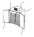
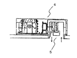
図7は、従来の低温貯蔵庫の斜視図、図8は、従来の低温貯蔵庫の貯蔵室の開口部を示した斜視図、図9は、従来の冷却装置の断面図である。   FIG. 7 is a perspective view of a conventional low temperature storage, FIG. 8 is a perspective view showing an opening of a storage chamber of a conventional low temperature storage, and FIG. 9 is a cross-sectional view of a conventional cooling device.

図7に示すように、低温貯蔵庫1は前面に扉3を有した断熱性の高い貯蔵室2の天面に冷却装置4を乗せている。   As shown in FIG. 7, the cold storage 1 has a cooling device 4 placed on the top surface of a highly heat-insulating storage room 2 having a door 3 on the front surface.

図8に示すように、冷却風は、低温貯蔵庫1の天面の開口5から貯蔵室2内に流し込むよう構成している。   As shown in FIG. 8, the cooling air is configured to flow into the storage chamber 2 from the opening 5 on the top surface of the low temperature storage 1.

図9に示すように、冷却装置4の内部構造は、冷却側には保冷庫内の空気を吸い込み、冷却後、吐き出すための角穴が低温貯蔵庫1の天面の開口5に相対して設けられている。また、冷却風は図9の矢印のように流れ、冷却側の周囲を断熱箱にて囲い、貯蔵室2側の冷気洩れを防止している。
特開2003−302141号公報
As shown in FIG. 9, the internal structure of the cooling device 4 is provided with a square hole for sucking the air in the cool box on the cooling side and discharging it after cooling, relative to the opening 5 on the top surface of the cold storage 1. It has been. Further, the cooling air flows as shown by the arrows in FIG. 9, and the cooling side is surrounded by a heat insulating box to prevent the cold air leakage on the storage chamber 2 side.
JP 2003-302141 A

しかしながら、上記従来の構成では、冷却装置4が貯蔵室2の天井面に乗っており、放熱のための風路確保のため、冷却装置4の面積以上の貯蔵室2の天井面を有効活用することができない。また、一般的にはこの種の低温貯蔵庫は農作物などの食品の冷却に広く利用され、大型の物が多く、冷却装置4の小型化とあいまって天井面の一部分に冷却装置4を置くのは、外観を損ねるだけでなくスペースの無駄が生じてしまう。さらに、農産物などを貯蔵する低温貯蔵庫は専門の食品業者だけではなく、民家の納屋などに設置するのが一般的となっており、低温貯蔵庫の設置搬入時には、納屋の引戸高さ、扉高さの制限があり、搬入ができない時は一担冷却装置4を取り外し、貯蔵室2と別搬入して納屋の中で再度組立てなければならず、納屋の天井が低い時は組立て作業性が悪く、場合によっては貯蔵室2の天面に乗って冷却装置4の取り付け作業ができない場合もある。   However, in the above conventional configuration, the cooling device 4 is on the ceiling surface of the storage chamber 2, and the ceiling surface of the storage chamber 2 that is larger than the area of the cooling device 4 is effectively used in order to secure an air passage for heat dissipation. I can't. In general, this type of low-temperature storage is widely used for cooling foods such as agricultural products, and there are many large items, and the cooling device 4 is placed on a part of the ceiling surface together with the downsizing of the cooling device 4. In addition to deteriorating the appearance, a waste of space occurs. Furthermore, low-temperature storage for storing agricultural products is generally installed not only in specialized food vendors but also in private barns, etc. When installing low-temperature storage, the height of the sliding door and the height of the door When it is impossible to carry in, the cooling device 4 must be removed, and it must be re-assembled in the barn separately from the storage room 2, and when the barn ceiling is low, the assembly workability is poor, In some cases, the cooling device 4 may not be mounted on the top surface of the storage chamber 2.

また、冷却装置4の故障などの修理の時、大量の冷却物を貯蔵室2から取り出し、冷却装置4の修理または交換を行い、再度、冷却物を元に戻すなど、作業が困難である、という課題を有していた。   In addition, when repairing a failure of the cooling device 4, it is difficult to take out a large amount of coolant from the storage chamber 2, repair or replace the cooling device 4, and return the coolant again. It had the problem that.

本発明は、上記従来の課題を解決するもので、貯蔵室2内に冷却装置4を収めることができ、貯蔵室2の天井面を平坦にすることで物を置くなどの有効活用ができるようにし、更に庫内が広く有効活用ができ、冷却装置4の修理点検などが容易に行える低温貯蔵庫を提供することを目的とする。   The present invention solves the above-described conventional problems, and can accommodate the cooling device 4 in the storage room 2 and can effectively use such as placing an object by flattening the ceiling surface of the storage room 2. Furthermore, an object of the present invention is to provide a low-temperature storage in which the inside of the storage can be used effectively and the repair of the cooling device 4 can be easily performed.

上記従来の課題を解決するために、本発明の低温貯蔵庫は、食品等を冷却貯蔵する貯蔵室と、前記貯蔵室を冷却する冷却部と放熱器および圧縮機を断熱材で囲った加熱部とからなる冷却装置を備え、前記冷却装置を前記貯蔵室の外部から設置でき、設置後は前記貯蔵室の外面から冷却装置がはみ出さないものである。   In order to solve the above-described conventional problems, the low-temperature storage according to the present invention includes a storage room that cools and stores food and the like, a cooling unit that cools the storage room, and a heating unit that surrounds a radiator and a compressor with a heat insulating material. The cooling device can be installed from the outside of the storage chamber, and the cooling device does not protrude from the outer surface of the storage chamber after installation.

これによって、貯蔵室の外側から貯蔵室内に冷却装置を収めることができ、貯蔵室の外面を平坦にすることで外観がよくなり、物を置くなどの有効活用ができるとともに、外部から取り付け取り外しができ、冷却装置の修理点検などが容易に行える。   As a result, the cooling device can be housed in the storage room from the outside of the storage room, and the external surface of the storage room is made flat to improve the appearance and make effective use such as placing objects, and can be attached and removed from the outside. It is possible to easily repair and inspect the cooling device.

本発明の低温貯蔵庫は、貯蔵室の外部から冷却装置を挿入するように設置するため、貯蔵室の断熱材の厚み分は冷却装置の構造として使えるため、内部に冷却装置をそのまま設置する場合に比べて、より少ない体積となるため貯蔵室内をより有効に活用することができる。また、冷却装置を貯蔵室の外側から挿入するように設置し、冷却装置の一面が貯蔵室の外面となるため、放熱器の廃熱や除霜水の排水が特殊な排気ダクトや排水ポンプなどを用いずに容易に構成できる。   Since the low-temperature storage of the present invention is installed so that the cooling device is inserted from the outside of the storage room, the thickness of the heat insulating material in the storage room can be used as the structure of the cooling device, so when installing the cooling device as it is inside Compared to the smaller volume, the storage chamber can be used more effectively. In addition, the cooling device is installed so as to be inserted from the outside of the storage room, and since one side of the cooling device is the outer surface of the storage room, the waste heat of the radiator and the drainage of defrost water are special exhaust ducts, drain pumps, etc. Can be easily configured without using

請求項1に記載の発明は、食品等を冷却貯蔵する貯蔵室と、貯蔵室を冷却する冷却部と放熱器および圧縮機を断熱材で囲った加熱部とからなる冷却装置を備え、前記冷却装置を前記貯蔵室の外部から設置でき、設置後は前記貯蔵室の外面から冷却装置がはみ出さないことにより、低温貯蔵庫は、貯蔵室の外側から貯蔵室内に冷却装置を収めることができ、同様に取り外しができるので、冷却装置の修理点検などが容易に行える。また、貯蔵室の外面を平坦にすることで外観がよくなり、物を置くなどの有効活用ができる。   The invention according to claim 1 is provided with a cooling device comprising a storage room for storing food and the like, a cooling unit for cooling the storage room, and a heating unit in which a radiator and a compressor are surrounded by a heat insulating material. The device can be installed from the outside of the storage chamber, and after installation, the cooling device does not protrude from the outer surface of the storage chamber, so that the low temperature storage can store the cooling device in the storage chamber from the outside of the storage chamber. Because it can be removed, the repair and inspection of the cooling device can be performed easily. In addition, by flattening the outer surface of the storage room, the appearance can be improved and effective use such as placing objects can be achieved.

請求項2に記載の発明は、請求項1に記載の発明において、前記冷却装置は、前記冷却部と前記加熱部とを同じ高さに配置し、前記冷却装置の垂直方向を薄く構成したことにより、貯蔵室の天井近くに配置することにより、貯蔵室内に入れる食品などの冷却物に邪魔にならず、貯蔵室内を有効活用することができる。   The invention according to claim 2 is the invention according to claim 1, wherein the cooling device is configured such that the cooling unit and the heating unit are arranged at the same height, and the vertical direction of the cooling device is thin. Thus, by disposing the storage chamber near the ceiling, the storage chamber can be effectively used without interfering with a cooling object such as food to be put in the storage chamber.

請求項3に記載の発明は、請求項1に記載の発明において、前記冷却装置は、前記冷却部と前記加熱部とを上下に配置し、前記冷却装置の水平方向を薄く構成したことにより、貯蔵室外部から冷却装置を取り付け取り外しをする際に、大型の貯蔵室では天井近くに設置するには、困難な場合があるが、冷却装置を上下に長く薄く構成すれば、冷却装置の重心位置が下がるため、比較的容易に冷却装置を設置することができる。また天井近くに設置しなくてもある程度、貯蔵室の中央や下に設置することも可能である。   The invention according to claim 3 is the invention according to claim 1, wherein the cooling device is configured such that the cooling unit and the heating unit are arranged vertically, and the horizontal direction of the cooling device is thinned. When installing / removing the cooling device from the outside of the storage room, it may be difficult to install it near the ceiling in a large storage room. Therefore, the cooling device can be installed relatively easily. In addition, it is possible to install in the center or below the storage room to some extent without installing it near the ceiling.

請求項4に記載の発明は、請求項2または3に記載の発明において、前記冷却装置は、前記貯蔵室内を冷却する循環風の吸い込み口と吹き出し口を水平または垂直の直線方向にした冷却装置で構成することにより、貯蔵室内の空気を吸い込みから吐き出しに対して直線方向に流すことで冷却器近傍での気流の抵抗が最も小さく最適に熱交換することができるので、冷却器や送風機を小型化することができる。   According to a fourth aspect of the present invention, in the invention according to the second or third aspect, the cooling device is a cooling device in which a suction port and a blowout port for circulating air for cooling the storage chamber are in a horizontal or vertical linear direction. By making the air in the storage chamber flow in a straight line direction from the suction to the discharge, the airflow resistance in the vicinity of the cooler can be minimized and optimal heat exchange can be achieved. Can be

以下、本発明の実施の形態について、図面を参照しながら説明する。なお、この実施の形態によってこの発明が限定されるものではない。   Hereinafter, embodiments of the present invention will be described with reference to the drawings. The present invention is not limited to the embodiments.

(実施の形態1)
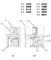
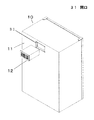
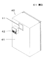
図1は、本発明の実施の形態1における低温貯蔵庫の背面側斜視図、図2(a)(b)は、同実施の形態の低温貯蔵庫の冷却装置の平面図と側面図、図3は、同実施の形態の低温貯蔵庫の冷却装置の取付け前の背面側斜視図を示す。
(Embodiment 1)
1 is a rear perspective view of a low-temperature storage according to Embodiment 1 of the present invention, FIGS. 2A and 2B are a plan view and a side view of a cooling device for a low-temperature storage according to the same embodiment, and FIG. The rear side perspective view before attachment of the cooling device of the low-temperature storage of the same embodiment is shown.

図1において、低温貯蔵庫10は、食品などを冷蔵する貯蔵室11と、冷却装置12とからなり、冷却装置12が貯蔵室11の外側から挿入するように設置される。   In FIG. 1, the low temperature storage 10 includes a storage room 11 that refrigerates food and the like and a cooling device 12, and the cooling device 12 is installed so as to be inserted from the outside of the storage room 11.

図2において、冷却装置12は冷却器21と送風機22と除霜水を受ける受け皿23とで構成された冷却部24と、放熱器25と圧縮機26と除霜水を蒸発させる蒸発皿27とで構成された加熱部28と、からなり、冷却部24と加熱部28とは断熱材29で仕切られている。ここで、冷却部24と加熱部28とは水平方向(貯蔵室の奥行き方向)に並んで配置し、冷却部24と加熱部28とを同じ高さに配置している。   In FIG. 2, the cooling device 12 includes a cooling unit 24 including a cooler 21, a blower 22, and a receiving tray 23 that receives defrosted water, a radiator 25, a compressor 26, and an evaporation tray 27 that evaporates the defrosted water. The cooling unit 24 and the heating unit 28 are partitioned by a heat insulating material 29. Here, the cooling unit 24 and the heating unit 28 are arranged side by side in the horizontal direction (the depth direction of the storage chamber), and the cooling unit 24 and the heating unit 28 are arranged at the same height.

図3において、貯蔵室11の背面側に冷却装置12の取付け用の開口31を設けて、冷却装置12を開口31に外側から挿入し設置する。   In FIG. 3, an opening 31 for mounting the cooling device 12 is provided on the back side of the storage chamber 11, and the cooling device 12 is inserted into the opening 31 from the outside and installed.

以上のように構成された低温貯蔵庫について、以下その動作、作用を説明する。   The operation and action of the low-temperature storage configured as described above will be described below.

まず、冷却装置12が貯蔵室11に設置される際には、貯蔵室11の断熱材と加熱部28を仕切っている断熱材29とが合わさり、冷却装置12の加熱部28は貯蔵室11内部から仕切られ、熱の流入が防がれる。これにより冷却側と放熱側が分断され、冷却装置12として機能することができる。さらに除霜水などは冷却装置12の外部露出面側に排水口を設ければよく、ポンプや配水管などを別に設置する必要が無く、加熱部28の外部からの吸排気は冷却装置12の挿入設置される外面となり、冷却装置12に吸排気口を設置することで、冷却装置12を組み入れるだけで低温貯蔵庫を完成させることができる。   First, when the cooling device 12 is installed in the storage chamber 11, the heat insulating material of the storage chamber 11 and the heat insulating material 29 partitioning the heating unit 28 are combined, and the heating unit 28 of the cooling device 12 is inside the storage chamber 11. This prevents the inflow of heat. Thereby, the cooling side and the heat radiating side are divided and can function as the cooling device 12. Furthermore, defrosted water or the like may be provided with a drain outlet on the externally exposed surface side of the cooling device 12, and there is no need to separately install a pump or a water distribution pipe. By installing an intake / exhaust port in the cooling device 12 as an outer surface to be inserted and installed, a low-temperature storage can be completed only by incorporating the cooling device 12.

また、本実施の形態では、冷却装置12の冷却部24と加熱部28とを同じ高さに配置し、冷却装置12の垂直方向を薄く構成したため、貯蔵室11の天井付近に設置することで、貯蔵室11内のスペースが広く邪魔にならない。   Further, in the present embodiment, the cooling unit 24 and the heating unit 28 of the cooling device 12 are arranged at the same height and the vertical direction of the cooling device 12 is thin, so that it is installed near the ceiling of the storage chamber 11. The space in the storage room 11 is wide and does not get in the way.

また、本実施の形態では、冷却装置12の冷却部24について冷却器21と送風機22が、貯蔵室11内部の空気の吸入口と冷却後の排気口を直線状に設置できるので、空気の流れが抵抗を受けることなく冷却器24に導入されるため、効率的に貯蔵室11内空気を冷却でき、冷却部24についても小型することができる。   Moreover, in this Embodiment, since the cooler 21 and the air blower 22 can install the air inlet and the exhaust port after cooling in the storage chamber 11 linearly about the cooling part 24 of the cooling device 12, the flow of air Is introduced into the cooler 24 without receiving resistance, the air in the storage chamber 11 can be efficiently cooled, and the cooling unit 24 can also be reduced in size.

(実施の形態2)
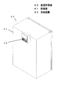
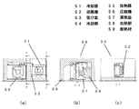
図4は、本発明の実施の形態2における低温貯蔵庫の背面側斜視図、図5(a)(b)(c)は、同実施の形態の低温貯蔵庫の冷却装置の側面図と平面図、図6は、同実施の形態の低温貯蔵庫の冷却装置の取付け前の背面側斜視図を示す。
(Embodiment 2)
4 is a rear perspective view of the low-temperature storage according to Embodiment 2 of the present invention, and FIGS. 5A, 5B, and 5C are a side view and a plan view of the cooling device for the low-temperature storage according to the same embodiment. FIG. 6: shows the back side perspective view before attachment of the cooling device of the low-temperature storage of the same embodiment.

図4において、低温貯蔵庫40は、食品などを冷蔵する貯蔵室41と、冷却装置42とからなり、冷却装置42が貯蔵室41の外側から挿入するように設置される。   In FIG. 4, the low temperature storage 40 includes a storage room 41 that refrigerates food and the like and a cooling device 42, and the cooling device 42 is installed so as to be inserted from the outside of the storage chamber 41.

図5において、冷却装置42は冷却器51と送風機52と除霜水を受ける受け皿53とで構成された冷却部54と、放熱器55と圧縮機56と除霜水を蒸発させる蒸発皿57とで構成された加熱部58と、からなり、加熱部58は断熱材59で仕切られている。ここで、冷却部54と加熱部58とは上下方向に配置している。   In FIG. 5, the cooling device 42 includes a cooling unit 54 including a cooler 51, a blower 52, and a receiving tray 53 that receives defrost water, a radiator 55, a compressor 56, and an evaporation tray 57 that evaporates the defrost water. And the heating unit 58 is partitioned by a heat insulating material 59. Here, the cooling unit 54 and the heating unit 58 are arranged in the vertical direction.

図6において、貯蔵室41の背面側に冷却装置42の取付け用の開口61を設けて、冷却装置42を開口61に外側から挿入し設置される。   In FIG. 6, an opening 61 for attaching the cooling device 42 is provided on the back side of the storage chamber 41, and the cooling device 42 is inserted into the opening 61 from the outside and installed.

以上のように構成された低温貯蔵庫について、以下その動作、作用を説明する。   The operation and action of the low-temperature storage configured as described above will be described below.

まず、冷却装置42が貯蔵室41に設置される際には、貯蔵室41の断熱材と加熱部58を仕切っている断熱材59とが合わさり、冷却装置42の加熱部58は貯蔵室41内部から仕切られ、熱の流入が防がれる。これにより冷却側と放熱側が分断され、冷却装置42として機能することができる。さらに除霜水などは冷却装置42の外部露出面側に排水口を設ければよく、ポンプや配水管などを別に設置する必要が無く、加熱部58の外部からの吸排気は冷却装置42の挿入設置される外面となり、冷却装置42に吸排気口を設置することで、冷却装置42を組み入れるだけで低温貯蔵庫40を完成させることが出来る。   First, when the cooling device 42 is installed in the storage chamber 41, the heat insulating material of the storage chamber 41 and the heat insulating material 59 partitioning the heating unit 58 are combined, and the heating unit 58 of the cooling device 42 is inside the storage chamber 41. This prevents the inflow of heat. Thereby, the cooling side and the heat radiating side are separated and can function as the cooling device 42. Furthermore, defrosted water or the like may be provided with a drain outlet on the externally exposed surface side of the cooling device 42, and there is no need to install a pump or a water pipe separately. By installing an intake / exhaust port in the cooling device 42 as an outer surface to be inserted and installed, the low temperature storage 40 can be completed only by incorporating the cooling device 42.

また、本実施の形態では、冷却装置42の冷却部54と加熱部58とを上下に配置し、冷却装置42の水平方向を薄く構成したため、貯蔵室41の天井付近に設置しても、重心位置が低い位置にあるので設置時や冷却装置42の交換時に冷却装置42を持ち上げるなどの作業がしやすい。また冷却装置42が薄く構成でき、貯蔵室41の断熱材の幅も冷却装置42を構成するスペースとして使えるため、従来の内面から冷却装置42を取り付けるような場合よりも薄く構成することができ、貯蔵室41内のスペースが広く邪魔にならない。   In the present embodiment, the cooling unit 54 and the heating unit 58 of the cooling device 42 are arranged up and down, and the horizontal direction of the cooling device 42 is thin. Since the position is low, it is easy to perform operations such as lifting the cooling device 42 at the time of installation or replacement of the cooling device 42. Moreover, since the cooling device 42 can be configured to be thin, and the width of the heat insulating material of the storage chamber 41 can be used as a space for configuring the cooling device 42, it can be configured to be thinner than the case where the cooling device 42 is attached from the conventional inner surface, The space in the storage room 41 is wide and does not get in the way.

また、本実施の形態では、冷却装置42の冷却部について冷却部54と送風機52にたいして、貯蔵室41内部の空気の吸入口と冷却後の排気口を直線状に設置できるので、空気の流れが抵抗を受けることなく冷却器51に導入されるため、効率的に貯蔵室41内空気を冷却でき、冷却部54についても小型することができる。   Moreover, in this Embodiment, since the air inlet and the exhaust outlet after cooling can be installed linearly with respect to the cooling part 54 and the air blower 52 in the cooling part of the cooling device 42, the flow of air is reduced. Since the air is introduced into the cooler 51 without receiving resistance, the air in the storage chamber 41 can be efficiently cooled, and the cooling unit 54 can be downsized.

以上のように、本発明にかかる低温貯蔵庫は、食品等を冷却貯蔵する貯蔵室に冷却装置を外部から設置でき、設置後は貯蔵室の外面から冷却装置がはみ出さず、比較的庫内スペースも小さくでき、民家の納屋など搬入の困難な場所であっても設置や修理交換などの作業も容易になる。冷却装置は単体で取り付いていることから、断熱性を持った箱体があればよいので、各種の保冷庫はもとより冷蔵庫・自販機等の用途にも適用できる。   As described above, the low-temperature storage according to the present invention can install a cooling device from the outside in a storage room that cools and stores food, etc., and after installation, the cooling device does not protrude from the outer surface of the storage room, and the space in the storage is relatively Even if it is difficult to carry in, such as a barn in a private house, installation and repair work can be facilitated. Since the cooling device is attached as a single unit, it is sufficient to have a box with heat insulation, so it can be applied to various refrigerators as well as refrigerators and vending machines.

本発明の実施の形態1における低温貯蔵庫の背面側斜視図The rear side perspective view of the low-temperature storage in Embodiment 1 of this invention (a)同実施の形態の低温貯蔵庫の冷却装置の平面図(b)同実施の形態の低温貯蔵庫の冷却装置の側面図(A) Plan view of the cooling device of the low temperature storage of the embodiment (b) Side view of the cooling device of the low temperature storage of the embodiment 同実施の形態の低温貯蔵庫の冷却装置の取付け前の背面側斜視図Rear side perspective view before mounting of cooling device of low-temperature storage of the same embodiment 本発明の実施の形態2における低温貯蔵庫の背面側斜視図The back side perspective view of the low-temperature storage in Embodiment 2 of this invention (a)同実施の形態の低温貯蔵庫の冷却装置の側面図(b)同実施の形態の低温貯蔵庫の冷却装置の平面図(c)同実施の形態の低温貯蔵庫の冷却装置の平面図(A) Side view of the cooling device for the low-temperature storage according to the embodiment (b) Plan view of the cooling device for the low-temperature storage according to the embodiment (c) Plan view of the cooling device for the low-temperature storage according to the embodiment 同実施の形態の低温貯蔵庫の冷却装置の取付け前の背面側斜視図Rear side perspective view before mounting of cooling device of low-temperature storage of the same embodiment 従来の低温貯蔵庫の斜視図Perspective view of conventional cold storage 従来の低温貯蔵庫の貯蔵室の開口部を示した斜視図The perspective view which showed the opening part of the storage room of the conventional low temperature store 従来の冷却装置の断面図Cross-sectional view of a conventional cooling device

符号の説明Explanation of symbols

10,40 低温貯蔵庫
11,41 貯蔵室
12,42 冷却装置
21,51 冷却器
22,52 送風機
23,53 受け皿
24,54 冷却部
25,55 放熱器
26,56 圧縮機
27,57 蒸発皿
28,58 加熱部
29,59 断熱材
31,61 開口
DESCRIPTION OF SYMBOLS 10,40 Low temperature storage 11,41 Storage chamber 12,42 Cooling device 21,51 Cooler 22,52 Air blower 23,53 Receptacle 24,54 Cooling part 25,55 Radiator 26,56 Compressor 27,57 Evaporating dish 28, 58 Heating part 29, 59 Heat insulation 31, 61 Opening

Claims (4)

食品等を冷却貯蔵する貯蔵室と、前記貯蔵室を冷却する冷却部と放熱器および圧縮機を断熱材で囲った加熱部とからなる冷却装置を備え、前記冷却装置を前記貯蔵室の外部から設置でき、設置後は前記貯蔵室の外面から前記冷却装置がはみ出さない低温貯蔵庫。   A cooling chamber comprising a storage chamber for cooling and storing food, etc., a cooling section for cooling the storage chamber, and a heating section in which a radiator and a compressor are surrounded by a heat insulating material, and the cooling apparatus is provided from the outside of the storage chamber A low-temperature storage that can be installed and does not protrude from the outer surface of the storage room after installation. 前記冷却部と前記加熱部とを同じ高さに配置し、前記冷却装置の垂直方向を薄く構成した請求項1に記載の低温貯蔵庫。   The low-temperature storage according to claim 1, wherein the cooling unit and the heating unit are arranged at the same height, and the vertical direction of the cooling device is thin. 前記冷却部と前記加熱部とを上下に配置し、前記冷却装置の水平方向を薄く構成した請求項1に記載の低温貯蔵庫。   The low-temperature storage according to claim 1, wherein the cooling unit and the heating unit are arranged one above the other and the horizontal direction of the cooling device is thin. 前記貯蔵室内を冷却する循環風の吸い込み口と吹き出し口を水平または垂直の直線方向にした冷却装置で構成した請求項2または3に記載の低温貯蔵庫。   The low-temperature storage according to claim 2 or 3, comprising a cooling device in which a suction port and a blow-out port for circulating air for cooling the storage chamber are arranged in a horizontal or vertical linear direction.
JP2007055613A 2007-03-06 2007-03-06 Cold storage Pending JP2008215744A (en)

Priority Applications (1)

Application Number Priority Date Filing Date Title
JP2007055613A JP2008215744A (en) 2007-03-06 2007-03-06 Cold storage

Applications Claiming Priority (1)

Application Number Priority Date Filing Date Title
JP2007055613A JP2008215744A (en) 2007-03-06 2007-03-06 Cold storage

Publications (1)

Publication Number Publication Date
JP2008215744A true JP2008215744A (en) 2008-09-18

Family

ID=39835986

Family Applications (1)

Application Number Title Priority Date Filing Date
JP2007055613A Pending JP2008215744A (en) 2007-03-06 2007-03-06 Cold storage

Country Status (1)

Country Link
JP (1) JP2008215744A (en)

Cited By (2)

* Cited by examiner, † Cited by third party
Publication number Priority date Publication date Assignee Title
WO2022059283A1 (en) * 2020-09-16 2022-03-24 パナソニックIpマネジメント株式会社 Refrigerator
KR102442001B1 (en) * 2022-02-11 2022-09-13 쿠팡 주식회사 cold storage system

Cited By (9)

* Cited by examiner, † Cited by third party
Publication number Priority date Publication date Assignee Title
WO2022059283A1 (en) * 2020-09-16 2022-03-24 パナソニックIpマネジメント株式会社 Refrigerator
JP2022049562A (en) * 2020-09-16 2022-03-29 パナソニックIpマネジメント株式会社 refrigerator
CN116057335A (en) * 2020-09-16 2023-05-02 松下知识产权经营株式会社 Cold storage
JP7417947B2 (en) 2020-09-16 2024-01-19 パナソニックIpマネジメント株式会社 refrigerator
CN116057335B (en) * 2020-09-16 2025-11-21 松下知识产权经营株式会社 Refrigerator with a door
KR102442001B1 (en) * 2022-02-11 2022-09-13 쿠팡 주식회사 cold storage system
WO2023153546A1 (en) * 2022-02-11 2023-08-17 쿠팡 주식회사 Cold storage system
TWI850968B (en) * 2022-02-11 2024-08-01 韓商韓領有限公司 Cold storage system
TWI885969B (en) * 2022-02-11 2025-06-01 韓商韓領有限公司 Cold storage system

Similar Documents

Publication Publication Date Title
JP2005172413A (en) Heat radiator for built-in refrigerator
US11156395B2 (en) Refrigerator
JPWO2011114656A1 (en) refrigerator
CN102345959B (en) Refrigerator
JP2009079778A (en) refrigerator
CN104380015B (en) refrigerator
US11808512B2 (en) Entrance refrigerator
JP2008215744A (en) Cold storage
JP2018048798A (en) refrigerator
JP2008292019A (en) Cooling storage
JP5633973B2 (en) refrigerator
JP2009002596A (en) Cooling unit
CN112413965B (en) Air-cooled horizontal refrigerator
JP2012255638A (en) Refrigerator
JP2007064601A (en) refrigerator
JP5359555B2 (en) Insulated rice container
JP2005042953A (en) Refrigerator
JP3863697B2 (en) Refrigerator
KR20130120022A (en) Refrigerator
JP2007064497A (en) Refrigeration storage box
JP2010175110A (en) Cooling storage
JP2011163610A (en) Cold insulation rice dispenser
JP2005345060A (en) refrigerator
KR100484661B1 (en) Refrigerator increased with inner space
JP4383904B2 (en) Cooling storage