JP2008226830A - Vacuum switchgear - Google Patents
Vacuum switchgear Download PDFInfo
- Publication number
- JP2008226830A JP2008226830A JP2008026260A JP2008026260A JP2008226830A JP 2008226830 A JP2008226830 A JP 2008226830A JP 2008026260 A JP2008026260 A JP 2008026260A JP 2008026260 A JP2008026260 A JP 2008026260A JP 2008226830 A JP2008226830 A JP 2008226830A
- Authority
- JP
- Japan
- Prior art keywords
- vacuum
- main circuit
- switch
- movable
- grounded
- Prior art date
- Legal status (The legal status is an assumption and is not a legal conclusion. Google has not performed a legal analysis and makes no representation as to the accuracy of the status listed.)
- Granted
Links
Images


Classifications
-
- H—ELECTRICITY
- H01—ELECTRIC ELEMENTS
- H01H—ELECTRIC SWITCHES; RELAYS; SELECTORS; EMERGENCY PROTECTIVE DEVICES
- H01H33/00—High-tension or heavy-current switches with arc-extinguishing or arc-preventing means
- H01H33/60—Switches wherein the means for extinguishing or preventing the arc do not include separate means for obtaining or increasing flow of arc-extinguishing fluid
- H01H33/66—Vacuum switches
- H01H33/666—Operating arrangements
- H01H33/6661—Combination with other type of switch, e.g. for load break switches
-
- H—ELECTRICITY
- H01—ELECTRIC ELEMENTS
- H01H—ELECTRIC SWITCHES; RELAYS; SELECTORS; EMERGENCY PROTECTIVE DEVICES
- H01H33/00—High-tension or heavy-current switches with arc-extinguishing or arc-preventing means
- H01H33/60—Switches wherein the means for extinguishing or preventing the arc do not include separate means for obtaining or increasing flow of arc-extinguishing fluid
- H01H33/66—Vacuum switches
-
- H—ELECTRICITY
- H01—ELECTRIC ELEMENTS
- H01H—ELECTRIC SWITCHES; RELAYS; SELECTORS; EMERGENCY PROTECTIVE DEVICES
- H01H1/00—Contacts
- H01H1/58—Electric connections to or between contacts; Terminals
- H01H1/5822—Flexible connections between movable contact and terminal
-
- H—ELECTRICITY
- H01—ELECTRIC ELEMENTS
- H01H—ELECTRIC SWITCHES; RELAYS; SELECTORS; EMERGENCY PROTECTIVE DEVICES
- H01H33/00—High-tension or heavy-current switches with arc-extinguishing or arc-preventing means
- H01H33/60—Switches wherein the means for extinguishing or preventing the arc do not include separate means for obtaining or increasing flow of arc-extinguishing fluid
- H01H33/66—Vacuum switches
- H01H33/666—Operating arrangements
- H01H2033/6668—Operating arrangements with a plurality of interruptible circuit paths in single vacuum chamber
-
- H—ELECTRICITY
- H01—ELECTRIC ELEMENTS
- H01H—ELECTRIC SWITCHES; RELAYS; SELECTORS; EMERGENCY PROTECTIVE DEVICES
- H01H31/00—Air-break switches for high tension without arc-extinguishing or arc-preventing means
- H01H31/003—Earthing switches
-
- H—ELECTRICITY
- H01—ELECTRIC ELEMENTS
- H01H—ELECTRIC SWITCHES; RELAYS; SELECTORS; EMERGENCY PROTECTIVE DEVICES
- H01H33/00—High-tension or heavy-current switches with arc-extinguishing or arc-preventing means
- H01H33/60—Switches wherein the means for extinguishing or preventing the arc do not include separate means for obtaining or increasing flow of arc-extinguishing fluid
- H01H33/66—Vacuum switches
- H01H33/662—Housings or protective screens
- H01H33/66207—Specific housing details, e.g. sealing, soldering or brazing
Landscapes
- High-Tension Arc-Extinguishing Switches Without Spraying Means (AREA)
- Gas-Insulated Switchgears (AREA)
Abstract
【課題】対地絶縁信頼性を向上させた多回路形の真空スイッチギヤを提供することを目的とする。
【解決手段】非接地型真空容器と、該非接地型真空容器内に収納され、可動電極および固定電極を含む複数の主回路開閉器と、該主回路開閉器のそれぞれの該固定電極に接続され、該非接地型真空容器から外方に延びたブッシング導体と、該主回路開閉器に対応して接地開閉器用真空容器または接地開閉器用気中容器内に収納された接点を有する接地開閉器と、該主回路開閉器のそれぞれの該可動電極に操作機構の運動を伝達するために接続された気中絶縁体と、該非接地型真空容器、該ブッシング導体および該接地開閉器用真空容器の外周を一体的に気密に絶縁モールドする接地樹脂モールド容器と、該接地樹脂モールド容器の一端に気密に取付けられた蓋体とを備える。
【選択図】図4An object of the present invention is to provide a multi-circuit type vacuum switchgear with improved ground insulation reliability.
A non-grounded vacuum vessel, a plurality of main circuit switches housed in the non-grounded vacuum vessel and including a movable electrode and a fixed electrode, and connected to each fixed electrode of the main circuit switch A bushing conductor extending outward from the non-grounding vacuum vessel, and a grounding switch having a contact accommodated in a grounding switch vacuum vessel or a grounding switch air vessel corresponding to the main circuit switch, The air insulator connected to transmit the motion of the operating mechanism to each movable electrode of the main circuit switch, and the outer periphery of the non-grounded vacuum vessel, the bushing conductor and the grounding switch vacuum vessel are integrated. A grounding resin mold container that is hermetically insulated and molded, and a lid that is airtightly attached to one end of the grounding resin mold container.
[Selection] Figure 4
Description
本発明は、真空スイッチギヤに係り、特に、容器内に複数の開閉器を備えた多回路形の真空スイッチギヤに関するものである。 The present invention relates to a vacuum switch gear, and more particularly to a multi-circuit type vacuum switch gear having a plurality of switches in a container.
多回路形の真空スイッチギヤは、例えば、需要側への配電のために、配電系統中に設置し使用される。この種の真空スイッチギヤとしては、容器内に複数の開閉器を備えた構成となっている。 The multi-circuit type vacuum switchgear is installed and used in a power distribution system, for example, for power distribution to a demand side. This type of vacuum switch gear has a configuration in which a plurality of switches are provided in a container.
特許文献1には、スイッチの固定電極側に接続する導体を樹脂でモールドしたモールド部と、前記固定電極とこれに接離可能な可動電極とを有するスイッチを収納し前記モールド部上に設置した真空容器とを備えた真空スイッチギヤが開示されている。
In
特許文献2には、夫々が異なる外部導体に繋がる固定電極と可動電極とを接離する開閉器を1または複数収納し、絶縁物によりモールドされており、外部導体に接続するための複数の端子がモールド部から突出している真空容器を備えたスイッチギヤが開示されている。
特許文献3には、真空容器と当該真空容器内に設置される所要数の開閉器とを備えた真空絶縁スイッチギヤにおいて、上記真空容器は金属材にて成形され絶縁物によりモールドされた真空絶縁スイッチギヤが開示されている。 Patent Document 3 discloses a vacuum insulation switchgear provided with a vacuum vessel and a required number of switches installed in the vacuum vessel, wherein the vacuum vessel is formed of a metal material and molded with an insulator. A switchgear is disclosed.
特許文献4には、固定側および可動側からなる主回路接点が真空容器内に設けられ、これらの両接点にそれぞれ接続された各主回路導体が上記真空容器の壁を貫通して配設されたスイッチギヤにおいて、上記真空容器の壁を貫通して一端が上記真空容器内の上記主回路導体の少なくとも一方に接離可能に配設された接地導体と、絶縁部材を介して上記真空容器から延出する上記接地導体の他端に連結された操作機構と、上記真空容器から延出する上記接地導体の他端側に相対的に変位可能に連結された接地兼試験用端子とを備えているスイッチギヤが開示されている。
In
上述した多回路形の真空スイッチギヤは、需要側の容量変更等に伴う、接続替えを可能にする機能を有しているものであるが、この真空スイッチギヤの耐電圧性能が低下すると、その下流側の機器への影響が多大となる。このため、この真空スイッチギヤの信頼性の向上が要求されているとともに、安価で小形であることも要求されている。特に、近年においては、対地絶縁に対する信頼性が、強く要請されている。 The multi-circuit type vacuum switchgear described above has a function that enables connection switching accompanying a change in capacity on the demand side, etc., but if the withstand voltage performance of this vacuum switchgear decreases, The impact on downstream equipment is significant. For this reason, it is required to improve the reliability of the vacuum switch gear, and it is also required to be inexpensive and small. In particular, in recent years, reliability for ground insulation has been strongly demanded.
本発明は、上述の事柄に基づいてなされたもので、対地絶縁に対する信頼性を向上させた多回路形の真空スイッチギヤを提供することを目的とする。 The present invention has been made based on the above-described matters, and an object of the present invention is to provide a multi-circuit type vacuum switch gear with improved reliability against ground insulation.
本発明の真空スイッチギヤは、1つまたは複数の非接地型真空容器と、該1つの非接地型真空容器内に収納され、可動電極および固定電極を含む複数の主回路開閉器、または該複数の非接地型真空容器内のそれぞれに収納され、可動電極および固定電極を含み、隣接する可動電極に電気的に接続された該可動電極を有する複数の主回路開閉器と、該主回路開閉器のそれぞれの該固定電極に接続され、該非接地型真空容器から外方に延びたブッシング導体と、該主回路開閉器に対応して接地開閉器用真空容器または接地開閉器用気中容器内に収納された接点を有する接地開閉器と、該主回路開閉器のそれぞれの該可動電極に操作機構の運動を伝達するために接続された気中絶縁体と、該非接地型真空容器、該ブッシング導体および該接地開閉器用真空容器の外周を一体的に気密に絶縁モールドする接地樹脂モールド容器と、該接地樹脂モールド容器の一端に気密に取付けられた蓋体とを備えたことを特徴とする。 The vacuum switchgear of the present invention includes one or a plurality of non-grounded vacuum containers, a plurality of main circuit switches housed in the one non-grounded vacuum container, and including a movable electrode and a fixed electrode, or the plurality A plurality of main circuit switches each having a movable electrode that is housed in each non-grounded vacuum vessel and includes a movable electrode and a fixed electrode and is electrically connected to the adjacent movable electrode, and the main circuit switch A bushing conductor that is connected to each of the fixed electrodes and extends outward from the non-grounded vacuum container, and is accommodated in a grounded switch vacuum container or a grounded switch air container corresponding to the main circuit switch. A grounding switch having contact points, an air insulator connected to transmit the movement of the operating mechanism to each movable electrode of the main circuit switch, the non-grounded vacuum vessel, the bushing conductor, and the Ground switch Characterized by comprising a ground resin mold container for insulating molded integrally hermetically the periphery of the vacuum container, and a lid attached hermetically to one end of the ground resin mold container.
本発明によれば、安価で小形であることは勿論のこと、多回路形の真空スイッチギヤにおける対地絶縁性能が向上し、その信頼性を更に向上させることができる。 According to the present invention, the ground insulation performance of a multi-circuit type vacuum switchgear can be improved as well as being inexpensive and small, and the reliability thereof can be further improved.
本発明の真空スイッチギヤは、1つまたは複数の非接地型真空容器と、該1つの非接地型真空容器内に収納され、可動電極および固定電極を含む複数の主回路開閉器、または該複数の非接地型真空容器内のそれぞれに収納され、可動電極および固定電極を含み、隣接する可動電極に電気的に接続された該可動電極を有する複数の主回路開閉器と、該主回路開閉器のそれぞれの該固定電極に接続され、該非接地型真空容器から外方に延びたブッシング導体と、該主回路開閉器に対応して接地開閉器用真空容器または接地開閉器用気中容器内に収納された接点を有する接地開閉器と、該主回路開閉器のそれぞれの該可動電極に操作機構の運動を伝達するために接続された気中絶縁体と、該非接地型真空容器、該ブッシング導体および該接地開閉器用真空容器の外周を一体的に気密に絶縁モールドする接地樹脂モールド容器と、該接地樹脂モールド容器の一端に気密に取付けられた蓋体とを備えたことを特徴とする。 The vacuum switchgear of the present invention includes one or a plurality of non-grounded vacuum containers, a plurality of main circuit switches housed in the one non-grounded vacuum container, and including a movable electrode and a fixed electrode, or the plurality A plurality of main circuit switches each having a movable electrode that is housed in each non-grounded vacuum vessel and includes a movable electrode and a fixed electrode and is electrically connected to the adjacent movable electrode, and the main circuit switch A bushing conductor that is connected to each of the fixed electrodes and extends outward from the non-grounded vacuum container, and is accommodated in a grounded switch vacuum container or a grounded switch air container corresponding to the main circuit switch. A grounding switch having contact points, an air insulator connected to transmit the movement of the operating mechanism to each movable electrode of the main circuit switch, the non-grounded vacuum vessel, the bushing conductor, and the Ground switch Characterized by comprising a ground resin mold container for insulating molded integrally hermetically the periphery of the vacuum container, and a lid attached hermetically to one end of the ground resin mold container.
また、本発明の真空スイッチギヤは、単一の容器内に複数の主回路開閉器を備えた多回路形の真空スイッチギヤであって、前記各主回路開閉器における固定電極とこれに接離する可動電極とを含む各主回路開閉部を、非接地型真空容器内にそれぞれ収納し、前記各可動電極を可撓性導体で連結し、かつ可動側操作ロッドを前記非接地型真空容器内に導入し絶縁体を介して前記各可動電極にそれぞれ連結し、前記主回路開閉部及び前記固定電極に接続するブッシング導体を絶縁する第1の絶縁部と、この第1の絶縁部と一体に形成され前記可動電極側及び前記可動側操作ロッド側を絶縁する第2の絶縁部とを、前記真空容器の外周に具備するモールド部を備えたことを特徴とする。 The vacuum switchgear according to the present invention is a multi-circuit type vacuum switchgear provided with a plurality of main circuit switches in a single container, and is connected to and separated from the fixed electrode in each main circuit switch. Each main circuit opening / closing portion including a movable electrode is housed in a non-grounded vacuum vessel, each movable electrode is connected by a flexible conductor, and a movable operation rod is connected in the non-grounded vacuum vessel. A first insulating part that is connected to each movable electrode through an insulator and insulates the bushing conductor connected to the main circuit opening / closing part and the fixed electrode; and the first insulating part integrally A mold part is provided that includes a second insulating part that is formed and insulates the movable electrode side and the movable operation rod side on the outer periphery of the vacuum vessel.
また、本発明の真空スイッチギヤは、絶縁樹脂モールド容器内に複数の主回路開閉器を備えた多回路形の真空スイッチギヤであって、前記各主回路開閉器における固定電極とこれに接離する可動電極とを含む主回路開閉部を、各真空容器内にそれぞれ収納し、前記各可動電極を可撓性導体で連結し、かつ可動側操作ロッドを前記各可動電極にそれぞれ連結し、前記主回路開閉部及び前記固定電極に接続するブッシング導体を絶縁する第1の絶縁部と、前記可撓性導体及び前記操作ロッド側を絶縁するように前記第1の絶縁部と一体に形成された第2の絶縁部とを含むモールド部を備えたことを特徴とする。 The vacuum switchgear according to the present invention is a multi-circuit type vacuum switchgear provided with a plurality of main circuit switches in an insulating resin molded container, and is connected to and separated from the fixed electrode in each main circuit switch. A main circuit opening / closing section including a movable electrode to be housed in each vacuum vessel, each movable electrode being connected by a flexible conductor, and a movable operation rod being connected to each movable electrode, A first insulating portion that insulates the bushing conductor connected to the main circuit opening / closing portion and the fixed electrode, and the first insulating portion so as to insulate the flexible conductor and the operation rod side. A mold part including the second insulating part is provided.
以下、本発明による真空スイッチギヤの実施例を、図面を用いて説明する。 Hereinafter, embodiments of the vacuum switchgear according to the present invention will be described with reference to the drawings.
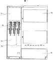
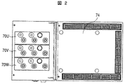
図1及び図2は、本発明の真空スイッチギヤの全体構成の一例で、変圧器が接続された例を示している。図1は正面図、図2は図1の平面図である。図1において、70は本発明の係る開閉器、71は操作器室、72はケーブル室、73はヒューズ室、74は変圧器室、75は低圧室である。図2において、70U、70V、70Wは、三相の電源それぞれの相に対応する開閉器を表している。 1 and 2 show an example of the overall configuration of the vacuum switchgear according to the present invention, in which a transformer is connected. 1 is a front view, and FIG. 2 is a plan view of FIG. In FIG. 1, 70 is a switch according to the present invention, 71 is a controller room, 72 is a cable room, 73 is a fuse room, 74 is a transformer room, and 75 is a low pressure room. In FIG. 2, 70U, 70V, and 70W represent switches corresponding to the phases of the three-phase power sources.
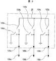
図3は、本発明の真空スイッチギヤの一例を示す結線図で、この例では3回路切り替えの例を示しており、この図3において、103A、103B、103Cは主回路開閉部、104A、104B、104Cは接地装置、105A、105B、105Cはブッシング、106A、106B、106Cはケーブルである。 FIG. 3 is a connection diagram showing an example of the vacuum switchgear according to the present invention. In this example, three circuits are switched. In FIG. 3, 103A, 103B, and 103C are main circuit opening / closing sections, and 104A and 104B. 104C are grounding devices, 105A, 105B and 105C are bushings, and 106A, 106B and 106C are cables.
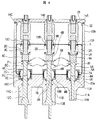
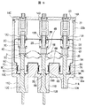
図4及び図5は、本発明による真空スイッチギヤの一実施例を示すもので、図4は縦断正面図、図5は図4の縦断側面図である。これらの図において、本実施例では、固定電極9A、9B、9Cと、この固定電極9A、9B、9Cにそれぞれに接離する可動電極5A、5B、5Cとを含む3つの主回路開閉部(電流遮断部)を備えている。これらの主回路開閉部は、非接地型真空容器1内に収納されている。非接地型真空容器1の内部は、減圧状態が保たれている。
4 and 5 show an embodiment of the vacuum switchgear according to the present invention. FIG. 4 is a longitudinal front view, and FIG. 5 is a longitudinal side view of FIG. In these drawings, in this embodiment, three main circuit opening / closing parts (including
固定電極9A、9B、9Cと可動電極5A、5B、5Cとの接点の近傍部分は、高導電性金属の銅(Cu)と低融点金属のテルル(Te)、ビスマス(Bi)またはスズ(Sn)との合金をマトリックスとし、耐火性金属のクロム(Cr)の粉末を分散した材料で形成されている。固定電極9A、9B、9Cおよび可動電極5A、5B、5Cの他の部分、すなわち電極棒は無酸素銅(純銅)で形成されている。上記合金と無酸素銅とは、ロウ付けにより接合されている。
A portion near the contact point between the
各主回路開閉部に対応する部分には、アークシールド7A、7B、7Cがそれぞれ設けられている。これらのアークシールド7A、7B、7Cの外周には、上側セラミック筒6A、6B、6Cと下側セラミック筒8A、8B、8Cとがそれぞれ配置されている。上側セラミック筒6A、6B、6Cは、その上部に可動電極5A、5B、5Cの貫通を許容する蓋部を有する構成となっている。下側セラミック筒8A、8B、8Cは、その下部に固定電極9A、9B、9Cの貫通を許容する蓋部を有する構成となっている。これらの下側セラミック筒8A、8B、8Cにおける固定電極9A、9B、9Cの貫通部分には、固定側シールリング10A、10B、10Cがそれぞれ設けられている。
固定電極9A、9B、9Cには、ブッシング導体12A、12B、12Cがそれぞれ一体的に連結されている。可動電極5A、5B、5C間は、表面側がベローズで覆われた可撓性導体20、21によって電気的に接続されている。この可撓性導体20、21により、可動電極5A、5B、5Cの電位が、電源の電位と等しくなっている。各可動電極5A、5B、5Cには、絶縁物4A、4B、4Cを介して可動操作ロッド3A、3B、3Cの一端がそれぞれ連結されている。可動操作ロッド3A、3B、3Cは、真空容器1の上部面に設けたガイド13A、13B、13Cを通して真空容器1外に導出され、その絶縁物4A、4B、4Cと接続している側とは反対側の端部は、気中絶縁操作ロッド14A、14B、14Cにそれぞれ連結されている。ガイド13A、13B、13Cが配置されている真空容器1の内側には、一端が真空容器1に、他端が可動操作ロッド3A、3B、3Cに接続されたベローズ2A、2B、2Cが、可動操作ロッド3A、3B、3Cが上下動できるように、それぞれ設けられており、このベローズ2A、2B、2Cで真空容器1内を気密保持している。
ここで、気中絶縁操作ロッド14A、14B、14Cを気中絶縁体と呼ぶことにする。気中絶縁体は、主回路開閉器のそれぞれの該可動電極に操作機構の運動を伝達するために接続されている。
Here, the air insulation operating
各主回路開閉部の固定電極9A、9B、9Cには、接地装置が接続されている。この接地装置を主回路開閉部の固定電極9Cに接続した例を、図5を用いて説明する。この図5において、図4と同符号のものは、同一部分であるので、その詳細な説明は省略する。接地装置は、接地装置固定電極37Cと接地装置可動電極31Cとを備えている。接地装置可動電極31Cには、接地装置用の気中絶縁操作ロッド30Cが連結されている。接地装置固定電極37Cは、導体38Cによって主回路開閉部の固定電極9Cに接続されている。接地装置固定電極37Cと接地装置可動電極31Cとの対向する部分には、接地装置アークシールド34Cが設けられている。
A grounding device is connected to the
この接地装置アークシールド34Cの外周には、接地装置上側セラミック筒33Cと接地装置下側セラミック筒35Cとがそれぞれ配置されている。接地装置上側セラミック筒33Cは、その上部に接地装置可動電極31Cの貫通を許容する蓋部を有する構成となっている。この接地装置上側セラミック筒33Cの蓋と接地装置可動電極31Cとの間には、接地装置ベローズ32Cが設けられている。
A grounding device upper
接地装置下側セラミック筒35Cは、その下部に接地装置固定電極37Cの貫通を許容する蓋部を有する構成となっている。この接地装置下側セラミック筒35Cにおける接地装置固定電極37Cの貫通部分には、接地装置固定側シールリング36Cが設けられている。
The grounding device lower
そして、本実施例では、非接地の前記真空容器1の外周に、モールド部22が形成されている。このモールド部22は、図4に示すように、主回路開閉部の固定電極9A、9B、9C側及び固定電極側のブッシング導体12A、12B、12Cを絶縁する第1の絶縁部22Aと、この第1の絶縁部22Aと一体に形成され、可動電極5A、5B、5C側及び可動操作ロッド3A、3B、3C側を絶縁する第2の絶縁部22Bとで構成されている。
In this embodiment, a
非接地型真空容器1、ブッシング導体12A、12B、12Cおよび接地開閉器用真空容器の外周は、一体的に気密に絶縁モールドされ、モールド部22が形成される。このモールド部22の一部である第2の絶縁部22Bの一端には、モールド蓋23、すなわち蓋体が気密に取付けられている。ここで、モールド部22とモールド蓋23とで仕切られた空間は、乾燥空気が封入されている。また、モールド部22を形成するエポキシ樹脂モールドの外面には、導電性ペースト、導電性塗料等を塗布し、外面の電位が等しくなるようにしてある。すなわち、モールド部22の外面は、接地装置を介して接地可能となっている。このモールド部22を接地樹脂モールド容器と呼ぶことにする。
The outer peripheries of the
ここで、非接地型真空容器1と接地開閉器用真空容器とを別々の真空容器としたのは、前者の真空容器内の真空度が低下した場合に、後者の真空容器が影響を受けないようにするためである。
Here, the
具体的には、第1の絶縁部22Aは、固定電極9A、9B、9Cに対応する真空容器1の外周及び固定電極側のブッシング導体12A、12B、12Cの外周面を覆うエポキシ樹脂モールドであり、第2の絶縁部22Bは、第1の絶縁部22Aであるエポキシ樹脂モールドと一体に形成され、可動電極5A、5B、5C側及び可動操作ロッド3A、3B、3C側に対応する真空容器1の外周を覆うエポキシ樹脂モールドである。また、接地装置は、図5に示すように、非接地型真空容器1とは別区画になっており、第1の絶縁部22Aによって非接地型真空容器1と一体的にモールドされている。更に、ブッシング導体12A、12B、12Cも、第1の絶縁部22Aであるエポキシ樹脂モールドと一体になって覆われ、絶縁ブッシング11A、11B、11Cをそれぞれ形成している。
Specifically, the first insulating portion 22A is an epoxy resin mold that covers the outer periphery of the
上述したように、この実施例においては、3つの主回路開閉部、可撓性導体20、21及び可動操作ロッド3A、3B、3Cの可動電極側の一部は、1つの非接地型真空容器1内に収納されるとともに、非接地型真空容器1外周面及び固定電極側のブッシング導体12A、12B、12Cの外周面を覆う第1の絶縁部22A、及び第2の絶縁部22Bによって絶縁され、可動操作ロッド3A、3B、3Cは、ベローズ2A、2B、2Cを介して真空容器1外に導出されて、気中絶縁される構成となっている。
As described above, in this embodiment, the three main circuit opening / closing sections, the
図5においては、可動電極5Cおよび固定電極9Cの接点、すなわち主回路開閉器の可動接点および固定接点を、モールド部22の一領域に形成した接点収納部内に設置してある。可動接点および固定接点とは、固定電極9Cと可動電極5Cとの接点の近傍部分であり、無酸素銅で形成されている電極棒の端部にロウ付けされた銅合金で形成されている。この銅合金の構成は上述の通りである。
In FIG. 5, the contacts of the
接点収納部は、モールド部22の内側の非接地型真空容器1が設置されている部分の最奥部に形成した、第1の絶縁部22Aの凹部に設置されている。この接点収納部は、上側セラミック筒6C、下側セラミック筒8Cおよび固定側シールリング10Cで構成されている。また、接点収納部の内部には、アークシールド7Cが設置されている。本実施例では、接点収納部が、第1の絶縁部22Aの凹部に設置してあり、下側セラミック筒8Cおよび固定側シールリング10Cがモールド部22で覆われているが、必ずしも第1の絶縁部22Aの凹部である必要はなく、下側セラミック筒8Cおよび固定側シールリング10Cがモールド部22で覆われていなくてもよい。すなわち、下側セラミック筒8Cが非接地型真空容器1内に露出していてもよいし、または、下側セラミック筒8Cおよび固定側シールリング10Cが非接地型真空容器1内に露出していてもよい。
The contact housing part is installed in a recess of the first insulating part 22A formed in the innermost part of the part where the
本図のように、上側セラミック筒6Cの平面部に可動電極5Cの直径と同程度か若干大きめの穴を設けて可動電極5Cを貫通させた構造とすることにより、接点収納部の内部で可動電極5Cと固定電極9Cとが接離する際に放電等により発生する金属蒸気が真空容器1内の他の領域に拡散することを抑制することができる。
As shown in the figure, the upper
また、接地装置可動電極31Cおよび接地装置固定電極37Cの接点、すなわち接地開閉器の可動接点および固定接点を、モールド部22で覆われた接点収納部内に設置してある。この接点収納部は、上側セラミック筒33C、下側セラミック筒35Cおよび固定側シールリング36Cで構成されている。また、接点収納部の内部には、アークシールド34Cが設置されている。
Further, the contacts of the grounding device
ベローズ32C、上側セラミック筒33C、下側セラミック筒35Cおよび固定側シールリング36Cなどで仕切られた部分は真空(減圧状態)が保たれるようになっている。これを接地開閉器用真空容器と呼ぶことにする。また、接地開閉器は、主回路開閉器に対応して接地開閉器用真空容器内に収納された接点を有する。
The portion partitioned by the
また、図5においては、モールド蓋23を示していないが、図4と同様に、モールド蓋23を設置してもよい。
In FIG. 5, the
上述した本発明による真空スイッチギヤの一実施例によれば、1つの非接地型真空容器1内に、3つの主回路開閉部、可撓性導体20、21及び可動操作ロッド3A、3B、3Cの可動電極側の一部を収納し、ブッシング導体12A、12B、12Cの外周面を含む非接地型真空容器1の外周面にエポキシ樹脂モールドによる絶縁部を形成したので、対地絶縁信頼性を更に向上させた多回路形の真空スイッチギヤを提供することができる。
According to the above-described embodiment of the vacuum switchgear according to the present invention, the three main circuit opening / closing sections, the
また、この実施例においては、真空容器1を非接地としたので、絶縁性能が安定化し、構成が簡単となる。更に、各主回路開閉部におけるアークシールド7A、7B、7Cを、真空容器1に予め組み付けているので、その組み立て性が向上する。なお、各主回路開閉部は実使用時には、独立に操作されるため、電流をそれぞれの主回路開閉部で遮断または投入する際に、アークシールド7A、7B、7Cへの分流を生じることはない。
In this embodiment, since the
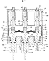
図6は、本発明による真空スイッチギヤの他の実施例を示す縦断正面図で、この図6において、図4及び図5に示す符号と同符号のものは、同一部分または相当する部分であるので、その詳細な説明を省略する。この実施例は、主回路開閉部における上側セラミック筒6A、6B、6Cおよび下側セラミック筒8A、8B、8Cを、円筒形にしたものである。
FIG. 6 is a longitudinal front view showing another embodiment of the vacuum switchgear according to the present invention. In FIG. 6, the same reference numerals as those shown in FIGS. 4 and 5 denote the same or corresponding parts. Therefore, the detailed description is abbreviate | omitted. In this embodiment, the upper
本図においては、図4、5の場合と異なり、上側セラミック筒6Cは平面部を有さず、円筒の側面部だけで構成されている。しかし、接点収納部を、モールド部22の内側の非接地型真空容器1が設置されている部分の最奥部に形成した、第1の絶縁部22Aの凹部に収納した構造とすることにより、接点収納部の内部で可動電極5Cと固定電極9Cとが接離する際に放電等により発生する金属蒸気が真空容器1内の他の領域に拡散することを抑制することができる。
In this figure, unlike the case of FIG. 4, 5, the upper
また、図4と同様に、モールド部22の一部である第2の絶縁部22Bの一端には、モールド蓋23、すなわち蓋体が気密に取付けられている。ここで、モールド部22とモールド蓋23とで仕切られた空間は、乾燥空気が封入されている。また、モールド部22を形成するエポキシ樹脂モールドの外面には、導電性ペースト、導電性塗料等を塗布し、外面の電位が等しくなるようにしてある。
Similarly to FIG. 4, a
この実施例によれば、前述した実施例と同様に、異物による地絡発生を抑え、信頼性を更に向上させた多回路形の真空スイッチギヤを提供することができる。また、主回路開閉部における上側セラミック筒6A、6B、6Cおよび下側セラミック筒8A、8B、8Cを、蓋部を持たない円筒形にしたことにより、上側セラミック筒6A、6B、6Cおよび下側セラミック筒8A、8B、8Cの構造が簡単化するので、コスト低減を図ることができる。
According to this embodiment, similarly to the above-described embodiment, it is possible to provide a multi-circuit type vacuum switch gear in which the occurrence of a ground fault due to a foreign object is suppressed and the reliability is further improved. Further, the upper
図7は、本発明の真空スイッチギヤの更に他の実施例を示す縦断正面図で、この図7において、図4乃至図6に示す符号と同符号のものは、同一部分または相当する部分であるので、その詳細な説明を省略する。この実施例は、図6に示した実施例における可撓性導体20、21を覆うベローズを取り除いて、可撓性導体20、21を単体のものとして、その構造を簡略化したものである。また、図6に示した真空容器1のガイド13A、13B、13C部分における気密保持のためのベローズ2A、2B、2Cを、真空容器1の上外側に配置して、真空容器1内の真空容積の低減を図るために、ベローズ2A、2B、2Cの下方部を真空容器1の外側上面に気密に取付け、その上方部を真空容器1外に導出した可動操作ロッド3A、3B、3Cに気密に取付けたものである。この場合、図示しないガイドを気中絶縁操作ロッド14A、14B、14Cに当接させることによって、可動側の上下運動方向を規定することができる。更に、図7中の右側の主回路開閉部に示すように、例えば、アークシールド7Aを真空容器1と一体にすれば、部品数を低減することも可能である。
FIG. 7 is a longitudinal front view showing still another embodiment of the vacuum switchgear of the present invention. In FIG. 7, the same reference numerals as those shown in FIGS. 4 to 6 denote the same or corresponding parts. Therefore, detailed description thereof is omitted. In this embodiment, the bellows covering the
この実施例によれば、前述した実施例と同様に、対地絶縁信頼性を更に向上させた多回路形の真空スイッチギヤを提供することができる。また、真空容器1内の真空容積、部品数の低減が可能となり、更なるコスト低減を図ることができる。
According to this embodiment, a multi-circuit type vacuum switchgear having further improved ground insulation reliability can be provided, as in the above-described embodiment. Further, the vacuum volume and the number of parts in the
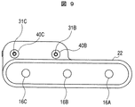
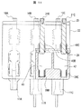
図8乃至図11は、本発明による真空スイッチギヤの他の実施例を示すもので、図8は縦断正面図、図9は図8の平面図、図10は図8の縦断側面図、図11は図8の縦断背面図である。これらの図8乃至図11において、この例では、固定電極9A、9B、9Cと、この固定電極9A、9B、9Cにそれぞれに接離する可動電極5A、5B、5Cとを含む3つの主回路開閉部(電流遮断部)を備えている。固定電極9A、9B、9Cには、ブッシング導体12A、12B、12Cがそれぞれ一体的に連結されている。
8 to 11 show another embodiment of the vacuum switchgear according to the present invention. FIG. 8 is a longitudinal front view, FIG. 9 is a plan view of FIG. 8, FIG. 10 is a longitudinal side view of FIG. 11 is a longitudinal rear view of FIG. 8 to 11, in this example, three main circuits including fixed
前述した各主回路開閉部は、真空容器1内にそれぞれ収納されている。真空容器1A、1B、1Cは、それぞれ上側セラミック筒6A、6B、6Cと、下側セラミック筒8A、8B、8Cと、上側セラミック筒6A、6B、6Cの上側に設けられ、可動電極5A、5B、5Cの導出部を有する可動側シールリング15A、15B、15Cと、下側セラミック筒8A、8B、8Cの下側に設けた固定側シールリング10A、10B、10Cと、可動側シールリング15A、15B、15C内側に配置され、一端が真空容器1A、1B、1C内の可動電極5A、5B、5Cに、他端が可動側シールリング15A、15B、15Cに気密に接続されたベローズ2A、2B、2Cで構成されている。すなわち、1つの非接地型真空容器が、主回路開閉器の固定電極および可動電極の一対を収納している。
Each of the main circuit opening / closing sections described above is housed in the
可動電極5A、5B、5Cにそれぞれ接続したベローズ2A、2B、2Cは、可動電極5A、5B、5Cが上下動を可能にするとともに、真空容器1内を気密保持している。各真空容器1A、1B、1C内の各主回路開閉部に対応する部分には、アークシールド7A、7B、7Cがそれぞれ設けられている。可動側シールリング15A、15B、15Cの上面には、真空容器1外に導出される可動電極5A、5B、5Cを案内するガイド13A、13B、13Cが設けてある。可動電極5A、5B、5Cの真空容器1外に導出された端部には、絶縁物14A、14B、14Cが設けられている。これらの絶縁物14A、14B、14Cに可動操作ロッド16A、16B、16Cがそれぞれ連結されている。
また、可動電極5A、5B、5Cの真空容器1A、1B、1C外に導出された端部は、導体25によって電気的に接続されているが、この接続は、導体25における可動電極5A、5B、5Cの貫通孔に設けたマルチコンタクト(集電子)41と、可動電極5A、5B、5Cとの接触により可能にしている。導体25は、ボルト26によって、後述するモールド部22に固定される。
The ends of the
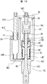
各主回路開閉部の固定電極9B、9Cには、図10及び図11に示すように、接地装置が接続されている。主回路開閉器の固定電極9Cについては、これに対応する接地装置は、図10及び図11に示すように、固定側コンタクト台39Cとこれに接離する接地装置可動電極31Cとを備えている。固定側コンタクト台39Cは、導体38Cによって固定電極9Cにそれぞれ接続されている。接地装置可動電極31Cは、マルチコンタクト(集電子)41を有するコンタクト台40Cによって案内される。なお、主回路開閉部の固定電極9Bについても、固定電極9Cと同様に接続される。
As shown in FIGS. 10 and 11, a grounding device is connected to the fixed
そして、本実施例では、前記各真空容器1の外周に、モールド部22が形成されている。このモールド部22は、図8に示すように、主回路開閉部の固定電極9A、9B、9C側及び固定電極側のブッシング導体12A、12B、12Cを絶縁する第1の絶縁部22Aと、この第1の絶縁部22Aと一体に形成され、各真空容器1外の可動電極5A、5B、5C側、導体25、絶縁物14A、14B、14C、可動操作ロッド16A、16B、16C側を絶縁する第2の絶縁部22Bとで構成されている。
In this embodiment, a
具体的には、モールド部22の第1の絶縁部22Aは、各真空容器の下側外周及び固定電極側のブッシング導体12A、12B、12Cの外周面を覆うエポキシ樹脂モールドであり、第2の絶縁部22Bは、導体25、絶縁物14A、14B、14Cを介して可動操作ロッド16A、16B、16C側を取り囲むように第1の絶縁部22Aであるエポキシ樹脂モールドと一体に形成されたエポキシ樹脂モールドである。モールド部22の外周面には、接地層が形成されている。
Specifically, the first insulating portion 22A of the
また、接地装置におけるコンタクト台40C及び固定側コンタクト台39Cも、前述したモールド部22の第1の絶縁部22Aによって一体的にモールドされている。
Further, the
モールド部22の第2の絶縁部22Bの上部には、モールド蓋23がシール24を介して取付けられている。このモールド蓋23は、可動操作ロッド16A、16B、16の貫通孔を有している。この貫通孔には、シール24を設けている。
A
なお、この実施例においては、接地装置は、固定電極9B、9Cにそれぞれ接続した例を示している。
In this embodiment, an example in which the grounding device is connected to the fixed
上述したように、この実施例においては、各主回路開閉部をそれぞれ個別の真空容器内に収納するとともに、これらの真空容器をエポキシ樹脂モールドによる第1の絶縁部22Aによって一体的にモールドし、可動電極5A、5B、5C側、導体25、絶縁物14A、14B、14C及び可動操作ロッド16A、16B、16C側に、これらを取り囲むように、第1の絶縁部22Aであるエポキシ樹脂モールドと一体に形成された第2の絶縁部22Bを設けて、可動電極5A、5B、5C側、導体25及び可動操作ロッド16A、16B、16C側を気中絶縁する構成となっている。
As described above, in this embodiment, each main circuit opening / closing part is housed in a separate vacuum container, and these vacuum containers are integrally molded by the first insulating part 22A using an epoxy resin mold, The
上述した本発明による真空スイッチギヤの他の実施例によれば、各主回路開閉部をそれぞれ個別の真空容器内に収納するとともに、これらの真空容器をエポキシ樹脂モールドによる第1の絶縁部22Aによって一体的にモールドし、可動電極5A、5B、5C側、導体25及び可動操作ロッド16A、16B、16C側に、これらを取り囲むように第1の絶縁部22Aであるエポキシ樹脂モールドと一体に形成された第2の絶縁部22Bを設けて、可動電極5A、5B、5C側、導体25及び可動操作ロッド16A、16B、16C側を気中絶縁する構成となっているので、対地絶縁信頼性を更に向上させた多回路形の真空スイッチギヤを提供することができる。
According to another embodiment of the above-described vacuum switchgear according to the present invention, each main circuit opening / closing portion is housed in a separate vacuum vessel, and these vacuum vessels are separated by an epoxy resin mold first insulating portion 22A. Molded integrally and formed integrally with the epoxy resin mold as the first insulating portion 22A on the
また、この実施例においては、可導側に、マルチコンタクト(集電子)41を有する導体25を配置固定したので、導体25に作用する磁気反発力が、可動電極5A、5B、5Cに伝達されないため、可動電極5A、5B、5Cに作用する電磁反発力を低減できる。更に、複数の開閉器を1つの真空容器内に収納する形式に比べて、真空容器が小形化になる。その結果、部品単価及び製作費が低減し、そのコストを大きく低減させることができるという利点を有する。
In this embodiment, since the
更に、この実施例においては、図11に示すように、接地装置における接地装置室42と接地装置室43とを近接するように、モールドすることも可能である。このように構成することにより、接地装置室の空間を小さくすることができるので、モールド使用量が少なくなり、原価低減を図ることができる。
Furthermore, in this embodiment, as shown in FIG. 11, the grounding
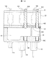
図12は、図8乃至図11に示す本発明による真空スイッチギヤの他の実施例を示す縦断背面図である。この図12において、図4乃至図11に示す符号と同符号のものは、同一部分または相当する部分であるので、その詳細な説明を省略する。この実施例は、接地装置における接地装置室43を広く構成したものである。
FIG. 12 is a longitudinal rear view showing another embodiment of the vacuum switchgear according to the present invention shown in FIGS. In FIG. 12, the same reference numerals as those shown in FIGS. 4 to 11 are the same or corresponding parts, and detailed description thereof will be omitted. In this embodiment, the grounding
この実施例によれば、接地装置可動電極31を上下動させたときに生じる接地装置室43内の圧力変化を抑えることができるので、シール24による封止性が良好となり、信頼性を向上させることができる。
According to this embodiment, since the pressure change in the
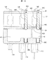
図13は、図8乃至図11に示す本発明の真空スイッチギヤの更に他の実施例を示す縦断背面図である。この図13において、図4乃至図12に示す符号と同符号のものは、同一部分または相当する部分であるので、その詳細な説明を省略する。この実施例は、接地装置可動電極31B、31Cの側面に、接地装置室を外気側に連通させるための連通用の溝44B、44Cをそれぞれ設けたものである。この連通用の溝44B、44Cは、接地装置の遮断動作時及び投入動作時のみ、接地装置室を外気側に連通することによって、接地装置室内の結露を防止するものである。
FIG. 13 is a longitudinal rear view showing still another embodiment of the vacuum switchgear according to the present invention shown in FIGS. In FIG. 13, the same reference numerals as those shown in FIGS. 4 to 12 are the same or corresponding parts, and detailed description thereof is omitted. In this embodiment,
なお、図8乃至図13に示す実施例では、気中絶縁形の接地装置を示したが、図5に示す真空絶縁形の接地装置を適用することも可能である。また、これとは逆に図5に示す実施例における真空絶縁形の接地装置を、気中絶縁形の接地装置にすることも可能である。 8 to 13 show the air-insulated grounding device, the vacuum-insulating grounding device shown in FIG. 5 can also be applied. On the contrary, the vacuum insulation type grounding device in the embodiment shown in FIG. 5 can be an air insulation type grounding device.
1:真空容器、2A、2B、2C:ベローズ、3A、3B、3C:可動操作ロッド、4A、4B、4C:絶縁物、5A、5B、5C:可動電極、6A、6B、6C:上側セラミック筒、7A、7B、7C:アークシールド、8A、8B、8C:下側セラミック筒、9A、9B、9C:固定電極、10A、10B、10C:固定側シールリング、11A、11B、11C:エポキシブッシング、12A、12B、12C:ブッシング導体、13A、13B、13C:ガイド、14A、14B、14C:気中絶縁操作ロッド、15A、15B、15C:可動側シールリング、16A、16B、16C:操作ロッド、20、21:可撓性導体、22:モールド部、22A:第1の絶縁部、22B:第2の絶縁部、23:モールド蓋、24:シール、25:導体、28:導体、31C:接地装置可動電極、32C:接地装置ベローズ、33C:接地装置上側セラミック筒、34C:接地装置アークシールド、35C:接地装置下側セラミック筒、36C:接地装置固定側シールリング、37C:接地装置固定電極。
1: Vacuum container, 2A, 2B, 2C: Bellows, 3A, 3B, 3C: Movable operation rod, 4A, 4B, 4C: Insulator, 5A, 5B, 5C: Movable electrode, 6A, 6B, 6C: Upper
Claims (7)
Priority Applications (1)
| Application Number | Priority Date | Filing Date | Title |
|---|---|---|---|
| JP2008026260A JP5060328B2 (en) | 2007-02-14 | 2008-02-06 | Vacuum switchgear |
Applications Claiming Priority (3)
| Application Number | Priority Date | Filing Date | Title |
|---|---|---|---|
| JP2007033006 | 2007-02-14 | ||
| JP2007033006 | 2007-02-14 | ||
| JP2008026260A JP5060328B2 (en) | 2007-02-14 | 2008-02-06 | Vacuum switchgear |
Publications (2)
| Publication Number | Publication Date |
|---|---|
| JP2008226830A true JP2008226830A (en) | 2008-09-25 |
| JP5060328B2 JP5060328B2 (en) | 2012-10-31 |
Family
ID=39445798
Family Applications (1)
| Application Number | Title | Priority Date | Filing Date |
|---|---|---|---|
| JP2008026260A Expired - Fee Related JP5060328B2 (en) | 2007-02-14 | 2008-02-06 | Vacuum switchgear |
Country Status (8)
| Country | Link |
|---|---|
| US (1) | US8354607B2 (en) |
| EP (1) | EP1959471B1 (en) |
| JP (1) | JP5060328B2 (en) |
| KR (1) | KR101052604B1 (en) |
| CN (1) | CN101246788B (en) |
| DE (1) | DE602008000912D1 (en) |
| SG (1) | SG145627A1 (en) |
| TW (1) | TW200841371A (en) |
Cited By (4)
| Publication number | Priority date | Publication date | Assignee | Title |
|---|---|---|---|---|
| JP2010119243A (en) * | 2008-11-14 | 2010-05-27 | Hitachi Ltd | Vacuum switchgear |
| JP2011041407A (en) * | 2009-08-12 | 2011-02-24 | Hitachi Ltd | Switch gear and operation method of switch gear |
| CN103632882A (en) * | 2013-12-10 | 2014-03-12 | 戴顿(重庆)高压开关有限公司 | Three-position disconnecting switch and vacuum switch integrated insulator |
| KR101619001B1 (en) | 2011-09-28 | 2016-05-09 | 미쓰비시덴키 가부시키가이샤 | Tank-type vacuum interrupter |
Families Citing this family (5)
| Publication number | Priority date | Publication date | Assignee | Title |
|---|---|---|---|---|
| JP5556237B2 (en) * | 2010-02-26 | 2014-07-23 | オムロン株式会社 | switch |
| JP5921269B2 (en) * | 2012-03-14 | 2016-05-24 | 株式会社日立製作所 | Switchgear |
| CN108199289A (en) * | 2018-03-16 | 2018-06-22 | 厦门业盛电气有限公司 | Solid insulation ring main unit |
| GB2582172B (en) * | 2019-03-13 | 2022-10-19 | As Tavrida Electric Exp | Insulated switchgear for electrical power systems |
| US20260120982A1 (en) * | 2023-03-07 | 2026-04-30 | Hitachi Energy Ltd | Fast earthing switch |
Citations (3)
| Publication number | Priority date | Publication date | Assignee | Title |
|---|---|---|---|---|
| JP2000306474A (en) * | 1999-04-19 | 2000-11-02 | Mitsubishi Electric Corp | Switchgear |
| JP2002152930A (en) * | 2000-11-14 | 2002-05-24 | Toshiba Corp | Sealed switchgear |
| JP2004056957A (en) * | 2002-07-23 | 2004-02-19 | Meidensha Corp | Switchgear |
Family Cites Families (8)
| Publication number | Priority date | Publication date | Assignee | Title |
|---|---|---|---|---|
| EP0017378B1 (en) * | 1979-03-23 | 1983-01-12 | Kabushiki Kaisha Meidensha | Vacuum circuit interrupter |
| JP3905266B2 (en) * | 1999-10-26 | 2007-04-18 | 三菱電機株式会社 | Vacuum insulated switchgear |
| AU3629199A (en) * | 1999-05-07 | 2000-11-21 | Mitsubishi Denki Kabushiki Kaisha | Vacuum switch gear |
| JP3577247B2 (en) * | 1999-11-10 | 2004-10-13 | 三菱電機株式会社 | Switchgear |
| TWI263236B (en) * | 2003-05-19 | 2006-10-01 | Hitachi Ltd | Vacuum switchgear |
| JP4360234B2 (en) * | 2004-03-12 | 2009-11-11 | 三菱電機株式会社 | Gas insulated switchgear |
| JP4162664B2 (en) * | 2005-02-22 | 2008-10-08 | 株式会社日立製作所 | Vacuum switchgear |
| JP4309386B2 (en) * | 2005-09-22 | 2009-08-05 | 株式会社東芝 | Switchgear |
-
2007
- 2007-11-15 TW TW096143185A patent/TW200841371A/en not_active IP Right Cessation
-
2008
- 2008-01-23 KR KR1020080007183A patent/KR101052604B1/en not_active Expired - Fee Related
- 2008-01-24 CN CN2008100040944A patent/CN101246788B/en not_active Expired - Fee Related
- 2008-02-04 DE DE602008000912T patent/DE602008000912D1/en active Active
- 2008-02-04 EP EP08002064A patent/EP1959471B1/en not_active Not-in-force
- 2008-02-05 SG SG200801009-2A patent/SG145627A1/en unknown
- 2008-02-05 US US12/025,966 patent/US8354607B2/en not_active Expired - Fee Related
- 2008-02-06 JP JP2008026260A patent/JP5060328B2/en not_active Expired - Fee Related
Patent Citations (3)
| Publication number | Priority date | Publication date | Assignee | Title |
|---|---|---|---|---|
| JP2000306474A (en) * | 1999-04-19 | 2000-11-02 | Mitsubishi Electric Corp | Switchgear |
| JP2002152930A (en) * | 2000-11-14 | 2002-05-24 | Toshiba Corp | Sealed switchgear |
| JP2004056957A (en) * | 2002-07-23 | 2004-02-19 | Meidensha Corp | Switchgear |
Cited By (4)
| Publication number | Priority date | Publication date | Assignee | Title |
|---|---|---|---|---|
| JP2010119243A (en) * | 2008-11-14 | 2010-05-27 | Hitachi Ltd | Vacuum switchgear |
| JP2011041407A (en) * | 2009-08-12 | 2011-02-24 | Hitachi Ltd | Switch gear and operation method of switch gear |
| KR101619001B1 (en) | 2011-09-28 | 2016-05-09 | 미쓰비시덴키 가부시키가이샤 | Tank-type vacuum interrupter |
| CN103632882A (en) * | 2013-12-10 | 2014-03-12 | 戴顿(重庆)高压开关有限公司 | Three-position disconnecting switch and vacuum switch integrated insulator |
Also Published As
| Publication number | Publication date |
|---|---|
| EP1959471B1 (en) | 2010-04-07 |
| TWI375246B (en) | 2012-10-21 |
| US8354607B2 (en) | 2013-01-15 |
| US20080190895A1 (en) | 2008-08-14 |
| DE602008000912D1 (en) | 2010-05-20 |
| JP5060328B2 (en) | 2012-10-31 |
| TW200841371A (en) | 2008-10-16 |
| SG145627A1 (en) | 2008-09-29 |
| HK1124168A1 (en) | 2009-07-03 |
| CN101246788B (en) | 2012-07-18 |
| CN101246788A (en) | 2008-08-20 |
| EP1959471A1 (en) | 2008-08-20 |
| KR101052604B1 (en) | 2011-07-29 |
| KR20080076726A (en) | 2008-08-20 |
Similar Documents
| Publication | Publication Date | Title |
|---|---|---|
| JP5060328B2 (en) | Vacuum switchgear | |
| CN101399133B (en) | Vacuum circuit interrupter grounding assembly | |
| US5387772A (en) | Vacuum switch | |
| US8110770B2 (en) | Vacuum circuit breaker of tank type | |
| EP3214709A1 (en) | Switchgear | |
| KR100887414B1 (en) | Vacuum Switching Device for medium and high voltage | |
| US5905242A (en) | High voltage hybrid circuit-breaker | |
| CN100587883C (en) | Vacuum switchgear | |
| EP1152444B1 (en) | Switch gear | |
| US11348748B2 (en) | Switch device | |
| JP2000268685A (en) | Switchgear | |
| EP0088442B1 (en) | Puffer type gas-blast circuit breaker | |
| CN101233593A (en) | Electrical switching device and method of operating an electrical switching device | |
| US10763062B2 (en) | Switching device with dual conductive housing | |
| CN1910800B (en) | Compressed-gas insulation switching device | |
| JP4011050B2 (en) | Vacuum switchgear | |
| HK1124168B (en) | Vacuum switchgear | |
| JP7686177B1 (en) | Gas insulated switchgear | |
| US4256940A (en) | Gas-blast type circuit interrupter | |
| EP4664696A1 (en) | Gas-insulated apparatus | |
| EP4345858A1 (en) | A switch, a load break switch and a switchgear | |
| CN112038168B (en) | High-voltage vacuum switch tube with double arc-extinguishing chambers | |
| JP2000149733A (en) | Multi-pole vacuum switch | |
| JP2018108026A (en) | Tank type vacuum circuit breaker | |
| JP2024157377A (en) | Insulating Switchgear |
Legal Events
| Date | Code | Title | Description |
|---|---|---|---|
| A621 | Written request for application examination |
Free format text: JAPANESE INTERMEDIATE CODE: A621 Effective date: 20091120 |
|
| A977 | Report on retrieval |
Free format text: JAPANESE INTERMEDIATE CODE: A971007 Effective date: 20111111 |
|
| A131 | Notification of reasons for refusal |
Free format text: JAPANESE INTERMEDIATE CODE: A131 Effective date: 20111122 |
|
| A521 | Written amendment |
Free format text: JAPANESE INTERMEDIATE CODE: A523 Effective date: 20120118 |
|
| A131 | Notification of reasons for refusal |
Free format text: JAPANESE INTERMEDIATE CODE: A131 Effective date: 20120529 |
|
| A521 | Written amendment |
Free format text: JAPANESE INTERMEDIATE CODE: A523 Effective date: 20120710 |
|
| TRDD | Decision of grant or rejection written | ||
| A01 | Written decision to grant a patent or to grant a registration (utility model) |
Free format text: JAPANESE INTERMEDIATE CODE: A01 Effective date: 20120731 |
|
| A01 | Written decision to grant a patent or to grant a registration (utility model) |
Free format text: JAPANESE INTERMEDIATE CODE: A01 |
|
| A61 | First payment of annual fees (during grant procedure) |
Free format text: JAPANESE INTERMEDIATE CODE: A61 Effective date: 20120803 |
|
| FPAY | Renewal fee payment (event date is renewal date of database) |
Free format text: PAYMENT UNTIL: 20150810 Year of fee payment: 3 |
|
| R150 | Certificate of patent or registration of utility model |
Free format text: JAPANESE INTERMEDIATE CODE: R150 |
|
| LAPS | Cancellation because of no payment of annual fees |