JP2008238024A - Grain milling apparatus - Google Patents
Grain milling apparatus Download PDFInfo
- Publication number
- JP2008238024A JP2008238024A JP2007080905A JP2007080905A JP2008238024A JP 2008238024 A JP2008238024 A JP 2008238024A JP 2007080905 A JP2007080905 A JP 2007080905A JP 2007080905 A JP2007080905 A JP 2007080905A JP 2008238024 A JP2008238024 A JP 2008238024A
- Authority
- JP
- Japan
- Prior art keywords
- mill
- grinding surface
- center side
- groove
- grain
- Prior art date
- Legal status (The legal status is an assumption and is not a legal conclusion. Google has not performed a legal analysis and makes no representation as to the accuracy of the status listed.)
- Pending
Links
- 238000003801 milling Methods 0.000 title claims abstract description 35
- 238000000227 grinding Methods 0.000 claims abstract description 53
- 230000002093 peripheral effect Effects 0.000 claims description 19
- 235000013339 cereals Nutrition 0.000 description 30
- 239000000843 powder Substances 0.000 description 15
- 235000013312 flour Nutrition 0.000 description 7
- 239000004570 mortar (masonry) Substances 0.000 description 5
- 241000219051 Fagopyrum Species 0.000 description 4
- 235000009419 Fagopyrum esculentum Nutrition 0.000 description 4
- 239000002245 particle Substances 0.000 description 4
- 240000007594 Oryza sativa Species 0.000 description 3
- 235000007164 Oryza sativa Nutrition 0.000 description 3
- 244000046052 Phaseolus vulgaris Species 0.000 description 3
- 235000010627 Phaseolus vulgaris Nutrition 0.000 description 3
- 230000005540 biological transmission Effects 0.000 description 3
- 238000010298 pulverizing process Methods 0.000 description 3
- 235000009566 rice Nutrition 0.000 description 3
- 230000008878 coupling Effects 0.000 description 2
- 238000010168 coupling process Methods 0.000 description 2
- 238000005859 coupling reaction Methods 0.000 description 2
- 230000000903 blocking effect Effects 0.000 description 1
- 239000000428 dust Substances 0.000 description 1
- 230000000694 effects Effects 0.000 description 1
- 239000002184 metal Substances 0.000 description 1
- 239000004575 stone Substances 0.000 description 1
Images




Classifications
-
- B—PERFORMING OPERATIONS; TRANSPORTING
- B02—CRUSHING, PULVERISING, OR DISINTEGRATING; PREPARATORY TREATMENT OF GRAIN FOR MILLING
- B02C—CRUSHING, PULVERISING, OR DISINTEGRATING IN GENERAL; MILLING GRAIN
- B02C7/00—Crushing or disintegrating by disc mills
- B02C7/11—Details
- B02C7/12—Shape or construction of discs
- B02C7/13—Shape or construction of discs for grain mills
-
- B—PERFORMING OPERATIONS; TRANSPORTING
- B02—CRUSHING, PULVERISING, OR DISINTEGRATING; PREPARATORY TREATMENT OF GRAIN FOR MILLING
- B02C—CRUSHING, PULVERISING, OR DISINTEGRATING IN GENERAL; MILLING GRAIN
- B02C7/00—Crushing or disintegrating by disc mills
- B02C7/18—Disc mills specially adapted for grain
- B02C7/184—Disc mills specially adapted for grain with vertical axis
Landscapes
- Engineering & Computer Science (AREA)
- Food Science & Technology (AREA)
- Crushing And Grinding (AREA)
Abstract
Description
本発明は、そば,米,豆などの穀粒を製粉する穀粒の製粉装置に関し、特に家庭用に好適な穀粒の製粉装置に関する。 The present invention relates to a grain milling apparatus for milling grains such as buckwheat, rice, and beans, and more particularly to a grain milling apparatus suitable for home use.
従来、この種の製粉装置としては、特開2001−137728に開示の様に、固定された下臼と回転する上臼とを有し、上臼の回転中心から偏心した位置に設けた縦孔へそば粒を落とし込み、上臼と下臼のテーパ状擦り合せ面へ導いて粉砕すると共に、そば粉がテーパ状擦り合せ面の中心から径方向外方に向って形成した溝条に沿ってテーパ擦り合せ面の外周縁に送り出されるようになっている。
上記の製粉装置は、上臼と下臼が石臼で重いため、テーパ状擦り合せ面では互いの対向ギャップ管理は不要であるものの、重量化と大型化を招き、家庭用製粉装置としては不向きな形態となっている。 In the above milling apparatus, since the upper and lower mills are heavy with a stone mill, it is not necessary to manage the opposing gaps on the tapered rubbing surface, but this increases the weight and size, and is unsuitable as a home milling machine. It has a form.
そこで、上記問題点に鑑み、本発明の課題は、軽量化及び小型化が可能で家庭用として好適な穀粒の製粉装置を提供することにある。 Then, in view of the said problem, the subject of this invention is providing the grain milling apparatus suitable for household use which can be reduced in weight and size.
上記課題を解決するため、請求項1に係る発明は、上に凸のテーパ状で中心側から外周方向に向けて第1の溝条を持つ下側粉砕面を有して回転駆動される下臼と、上に凹のテーパ状で中心側から外周方向に向けて第2の溝条を持ち下側粉砕面に対面する上側粉砕面及び中心軸線に沿う穀粒落し込み通孔を有して固定された上臼と、下臼を中心軸線に沿って上下可動して下側粉砕面と上側粉砕面との対向ギャップを調節する対向ギャップ調節手段とを備えて成ることを特徴とする。
In order to solve the above-mentioned problem, the invention according to
例えば殻剥きの穀粒を粉砕する場合は粒径が大きいので、対向ギャップ調節手段を操作し、下臼を下げて下側粉砕面と上側粉砕面との対向ギャップを大きく設定した後、下臼を回転駆動して落し込み通孔へ穀粒を投入すると、回転する下側粉砕面に穀粒が引き込まれて上側粉砕面との挟間で粉砕されながら粗い粉体が第1の溝条に沿って外周方向へ送り出される。次に、対向ギャップ調節手段を操作し、下臼を上げて下側粉砕面と上側粉砕面との対向ギャップを小さく設定した後、上記の粗い粉体を穀粒落し込み通孔へを投入することにより、今度は細かな粉体を得ることができる。また、米粒と豆粒などのように粒径が大きく異なるものでも製粉できる。 For example, when crushing unshelled grains, the particle size is large, so the opposing gap adjustment means is operated, the lower mill is lowered and the opposing gap between the lower grinding surface and the upper grinding surface is set large, then the lower milling When the grain is put into the drop-through hole by rotationally driving the coarse powder, the coarse powder is drawn along the first groove while the grain is drawn into the rotating lower grinding surface and pulverized between the upper grinding surface To the outer periphery. Next, the opposing gap adjusting means is operated, the lower mill is raised to set the opposing gap between the lower pulverized surface and the upper pulverized surface small, and then the coarse powder is dropped into the grain and put into the through hole. Thus, a fine powder can be obtained this time. In addition, it is possible to mill even grains having greatly different particle sizes such as rice grains and bean grains.
このように、本発明では下臼を回転臼として対向ギャップ調節手段を設けたため、製粉装置の小型化と軽量化を実現でき、家庭用製粉装置を提供できる。また、下臼が回転臼であるため、下臼の下側に配置する電動機からの駆動伝達機構を簡素化できる。 As described above, in the present invention, since the opposed gap adjusting means is provided with the lower mill as the rotary mill, the size and weight of the milling apparatus can be reduced, and the home milling apparatus can be provided. Moreover, since the lower die is a rotary die, the drive transmission mechanism from the electric motor arranged on the lower side of the lower die can be simplified.
請求項2に係る発明は、上に凸のテーパ状で中心側から外周方向に向けて第1の溝条を持つ下側粉砕面を有して回転駆動される下臼と、上に凹のテーパ状で中心側から外周方向に向けて第2の溝条を持ち下側粉砕面に対面する上側粉砕面及び中心軸線に沿う穀粒落し込み通孔を有して固定された上臼と、下臼の外周面に外嵌して第1の溝条の外周側の溝口を塞ぐ堰き止め部とを備えて成ることを特徴とする。
The invention according to
下側粉砕面の第1の溝条内で中心側から外周側へ案内される粉体は堰き止め部で堰き止められているため、下側粉砕面と上側粉砕面とに挟まれた粉砕空間には圧迫力が加わることになり、粉体が粗いまま外周側へ流れ出すことがなく、粉砕性能が向上する。 Since the powder guided from the center side to the outer peripheral side in the first groove on the lower pulverized surface is dammed by the damming portion, the pulverized space sandwiched between the lower pulverized surface and the upper pulverized surface A pressing force is applied to the powder, and the powder does not flow out to the outer peripheral side while being coarse, so that the pulverization performance is improved.
請求項3に係る発明は、上に凸のテーパ状で中心側から外周方向に向けて第1の溝条を持つ下側粉砕面を有して回転駆動される下臼と、上に凹のテーパ状で中心側から外周方向に向けて第2の溝条を持ち下側粉砕面に対面する上側粉砕面及び中心軸線に沿う穀粒落し込み通孔を有して固定された上臼と、下臼の頂上で当該下臼と一体的に回転し、下側粉砕面のテーパよりも急傾斜の斜歯状外歯を持つ前置粉砕体と、この前置粉砕体の上側に固定されて落し込み通孔に投入される穀粒を下方へ押し込む送りロールとを備え、落し込み通孔の孔壁には斜歯状外歯に離間対向する斜歯状内歯が形成されていることを特徴とする。
The invention according to
穀粒を穀粒落し込み通孔を介して下側粉砕面上へ直接投入した場合、下側粉砕面の中心側で穀粒の詰まりを生じ易いものの、上記のように、送りロールによる強制的な送り込みと、前置粉砕体と斜歯状外歯の前置粉砕処理部とよって、穀粒の詰まりを防止でき、粉砕性能が向上する。 When the grain is dropped directly onto the lower pulverized surface through the grain dropping hole, it is likely to clog the grain on the center side of the lower pulverized surface, but as described above, forced by the feed roll , And the pre-grinding part of the pre-ground body and the inclined external teeth can prevent clogging of grains and improve the grinding performance.
斜歯状内歯の傾斜は斜歯状外歯の傾斜よりも急であることがの望ましい。斜歯状内歯と斜歯状外歯との間隔を軸方向下側になるに従い徐々に狭くでき、穀粒の詰まりをなお一層防止できる。 It is desirable that the inclination of the inclined internal teeth is steeper than the inclination of the inclined external teeth. The interval between the inclined teeth and the inclined teeth can be gradually narrowed as it goes downward in the axial direction, and the clogging of the grains can be further prevented.
本発明によれば、下臼を回転臼として対向ギャップ調節手段を設けたため、製粉装置の小型化と軽量化を実現でき、家庭用製粉装置を提供できる。また、下臼が回転臼であるため、下臼の下側に電動機からの駆動伝達機構が簡素化する。 According to the present invention, since the opposing gap adjusting means is provided with the lower mill as the rotary mill, the size and weight of the milling apparatus can be reduced, and the home milling apparatus can be provided. Moreover, since the lower die is a rotary die, the drive transmission mechanism from the electric motor is simplified on the lower side of the lower die.
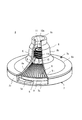
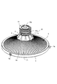
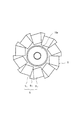
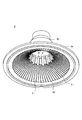
次の本発明の実施例を添付図面に基づいて説明する。図1は本発明の実施例に係る家庭用製粉装置を示す外観斜視図、図2は同家庭用製粉装置の製粉本体を示す縦断面図、図3は同製粉本体の分解斜視図、図4は同製粉本体の一部切欠斜視図、図5は同製粉本体の下臼アセンブリを示す斜視図、図6は同下臼アセンブリに用いる前置粉砕体を示す平面図、図7は同製粉本体の上臼を底面側から見た斜視図、図8は図2中のA−A′線で切断した状態を示す矢視図、図9は図2中のB−B′線で切断した状態を示す矢視図、図10は同下臼アセンブリの外周側部分を示す部分断面図である。 Embodiments of the present invention will be described with reference to the accompanying drawings. 1 is an external perspective view showing a home flour milling apparatus according to an embodiment of the present invention, FIG. 2 is a longitudinal sectional view showing a flour milling body of the home milling apparatus, FIG. 3 is an exploded perspective view of the flour milling body, FIG. Is a partially cutaway perspective view of the milling body, FIG. 5 is a perspective view showing a lower mill assembly of the milling body, FIG. 6 is a plan view showing a pre-ground body used in the milling body, and FIG. The perspective view which looked at the upper die from the bottom face side, FIG. 8 is an arrow view which shows the state cut | disconnected by the AA 'line in FIG. 2, FIG. 9 is the state cut | disconnected by the BB' line in FIG. FIG. 10 is a partial sectional view showing an outer peripheral side portion of the lower mortar assembly.
本例の製粉装置は、下側の筐体を取り外して示す図1のように、電動モータ1と一体的に取着されたギアボックス2と、このボックス上を横移動可能にスライドする楔ブロック3と、この楔ブロックの上で支持された製粉本体4と有する。製粉本体4は下臼アセンブリ5と上臼6とから成り、下臼アセンブリ5は、ベース7,下臼8,堰止めリム9,前置粉砕体10及び送りロール11を有する。
As shown in FIG. 1 with the lower casing removed, the milling apparatus of this example includes a
ベース7は、ボス部7aから端板部7bを介した環状壁7cと端板部7bのうち環状壁7c側に開口した粉落とし口7dを有し、装置固定部に固定されており、ボス部7a内にはスラスト方向変位可能な軸受ハウジング12が挿通している。この軸受ハウジング12は下端部に軸継手13aを持つ軸部13を有し、軸受ハウジング12の下端は楔ブロック3の楔面3aに接合する斜口面12aとなっている。
The
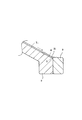
下臼8は、上に凸のテーパ状で中心側から外周方向に向けて第1の溝条V1を持つ下側粉砕面8aを有する金属製の傘型であり、中央面8bに軸部13が挿通する軸孔8cと植立ピンPを有している。この下臼8の外周面には堰止めリム9が外嵌し、止めネジ9aでネジ止めされている。図10に示す如く、堰止めリム9の内周面9bは、第1の溝条V1の外周側の溝口Qを塞いでいる。
The
前置粉砕体10は筒部10aの下側に複数の斜歯状外歯Gを一体的に持ち、この斜歯状外歯Gは、図8又は図9に示す如く、外接円C1又はC2を通る円弧面S1を境に回転方向の前縁段差面S2と反回転方向の後縁勾配面S3とから成り、前縁段差面S2と後縁勾配面S3とで外縦溝Wを形成している。斜歯状外歯Gの傾きは下側粉砕面8aのテーパよりも急傾斜となっている。この前置粉砕体10は下臼8の中央面8bの植立ピンPに挿入されて回り止めされる。送りロール11は、前置粉砕体10の筒部10aに外嵌する中空部11aと、外周面に左ネジのリードスクリュー溝11bと、前置粉砕体10の筒部10aから径方向外方へ突出する回り止めピンpに掛け止まる切り欠きKとを有する。なお、締め付けボルト10bを筒部10a内を介して軸部13のネジ孔13aに螺着することで、前置粉砕体10,下臼8及びベース7が組付けられる。
上臼6は、傘型部6aとその中央部分から上方へ延びる多段テーパー状の中央管部6bとから成る。傘型部6aの底面は、上に凹のテーパ状で中心側から外周方向に向けて第2の溝条V2を持つ上側粉砕面6dであって、下臼8の上側粉砕面8aを覆っている。この傘型部6aの外周側はベース7の環状壁7cの回り止めピン7eで回り止めされている。中央管部6bの中空は穀粒落し込み通孔6cとなっている。この落し込み通孔6cの孔壁のうち第2の溝条V2の中心側に連絡する部分には斜歯状外歯Gに離間対向する斜歯状内歯gが形成されている。この斜歯状内歯gは、図8又は図9に示す如く、内接円C1′又はC2′を通る円弧面S1′を境に段差面S2′と回転方向の勾配面S3′から成り、段差面S2′と勾配面S3とで内縦溝W′を形成している。この斜歯状内歯gの傾斜は斜歯状外歯Gの傾斜よりも急である。
The
ここで、楔ブロック3の楔面3aと下臼アセンブル5の斜口面12aとは対向ギャップ調整機構を構成しており、楔ブロック3を操作して横移動させると、軸受ハウジング12が上下動して下臼アセンブル5もこれに追動する。このため、下臼8の下側粉砕面8aと上臼6の上側粉砕面6dととの対向ギャップを調整できる。なお、下臼アセンブル5の荷重は軸部12ではなく楔ブロック3の楔面3aで受けていることから、軸部12の小径化により下側粉砕面8aの面積比率を向上できる。
Here, the
例えばそばの剥き実を粉砕する場合は粒径が大きいので、楔ブロック3を操作し、下臼アセンブリ5を下げて下側粉砕面8aと上側粉砕面6dとの対向ギャップを大きく設定した後、下臼8を回転駆動して穀粒落し込み通孔6cへ剥き実を投入すると、回転する下側粉砕面8cに剥き実が引き込まれて上側粉砕面6dとの挟間で粉砕されながら粗い粉体が第1の溝条V1に沿って外周方向へ送り出される。次に、下臼8を上げて下側粉砕面8aと上側粉砕面6dとの対向ギャップを小さく設定した後、上記の粗い粉体を穀粒落し込み通孔6cへ投入することにより、今度は細かな粉体を得ることができる。また、米粒と豆粒などのように粒径が大きく異なるものでも、対向ギャップを調節できるため、微粉末の製粉が可能である。
For example, when crushing buckwheat peel, the particle size is large, so after operating the
このように、本例では下臼8を回転臼として対向ギャップ調節手段を設けたため、製粉装置の小型化と軽量化を実現でき、家庭用製粉装置を提供できる。また、下臼8が回転臼であるため、下臼8の下側に配置する電動モータ1からの駆動伝達機構を簡素化できる。
Thus, in this example, since the opposing gap adjusting means is provided using the
更に本例では、下臼8の外周面に外嵌して第1の溝条V1の外周側の溝口Qを塞ぐ堰き止めリム9が取着されているため、図10に示す如く、第1の溝条V1内で中心側から外周側へ案内される粉体Mは堰き止めリム9で堰き止められて一時的に停滞するので、下側粉砕面8aと上側粉砕面6dとに挟まれた粉砕空間には圧迫力が加わることになり、粉体が粗いまま外周側へ流れ出すことがなく、粉砕性能が向上する。特に、斜歯状外歯Gの前縁段差面S2で後押しされる穀粒が斜歯状内歯gの段差面S2に激突するため、穀粒を砕く効果が大きい。
Further in this example, since the
本例では、下臼8の頂上で当該下臼8と一体的に回転し、下側粉砕面8aのテーパよりも急傾斜の斜歯状外歯Gを持つ前置粉砕体10と、この前置粉砕体10の上側に固定された送りロール11とを備えているため、下側粉砕面8aの中心側で穀粒の詰まりを生じ難く、粉砕性能が向上する。加えて、斜歯状内歯gと斜歯状外歯Gとの間隔が軸方向下側になるに従い徐々に狭くなっているため、穀粒の詰まりをなお一層防止できる。
In this example, the
1…電動モータ
2…ギアボックス
3…楔ブロック
3a…楔面
4…製粉本体
5…下臼アセンブリ5
6…上臼
6a…傘型部
6b…中央管部
6c…穀粒落し込み通孔
6d…上側粉砕面
7…ベース
7a…ボス部
7b…端板部
7c…環状壁
7d…粉落とし口
7e,p…回り止めピン
8…下臼
8a…下側粉砕面
8b…中央面
8c…軸孔
9…堰止めリム
9a…止めネジ
9b…内周面
10…前置粉砕体
10a…筒部
10b…締め付けボルト
11…送りロール
11a…中空部
11b…リードスクリュー溝
12…軸受ハウジング
12a…斜口面
13…軸部
13a…軸継手
13b…ネジ孔
G…斜歯状外歯
g…斜歯状内歯
C1,C2…外接円
C1′,C2′…内接円
K…切り欠き
M…粉体
P…植立ピン
Q…溝口
S1,S1′…円弧面
S2…前縁段差面
S3…後縁勾配面
S2′…段差面
S3′…勾配面
V1…第1の溝条
V2…第2の溝条
W…外縦溝
W′…内縦溝
DESCRIPTION OF
6 ...
Claims (4)
Priority Applications (1)
| Application Number | Priority Date | Filing Date | Title |
|---|---|---|---|
| JP2007080905A JP2008238024A (en) | 2007-03-27 | 2007-03-27 | Grain milling apparatus |
Applications Claiming Priority (1)
| Application Number | Priority Date | Filing Date | Title |
|---|---|---|---|
| JP2007080905A JP2008238024A (en) | 2007-03-27 | 2007-03-27 | Grain milling apparatus |
Publications (1)
| Publication Number | Publication Date |
|---|---|
| JP2008238024A true JP2008238024A (en) | 2008-10-09 |
Family
ID=39909999
Family Applications (1)
| Application Number | Title | Priority Date | Filing Date |
|---|---|---|---|
| JP2007080905A Pending JP2008238024A (en) | 2007-03-27 | 2007-03-27 | Grain milling apparatus |
Country Status (1)
| Country | Link |
|---|---|
| JP (1) | JP2008238024A (en) |
Cited By (12)
| Publication number | Priority date | Publication date | Assignee | Title |
|---|---|---|---|---|
| CN102773136A (en) * | 2011-05-12 | 2012-11-14 | 嘉兴溢联电子有限公司 | Pulverizer of kitchen waste disposer |
| KR101384778B1 (en) * | 2013-07-05 | 2014-04-14 | 박영옥 | Grinding gap regulation device for crusher |
| JP2014083516A (en) * | 2012-10-25 | 2014-05-12 | Kubota Corp | Flour mill |
| CN105682805A (en) * | 2013-10-14 | 2016-06-15 | 耐驰精细研磨技术有限公司 | Pre-comminuting device for a ball mill or agitator ball mill, and ball mill with pre-comminuting device |
| CN106391201A (en) * | 2016-11-23 | 2017-02-15 | 卓锦华 | Cereal grinding method |
| KR101930886B1 (en) * | 2018-09-03 | 2018-12-19 | (주)동일전자 | Grinder capable precision control grinding gap |
| KR20200080806A (en) * | 2018-12-27 | 2020-07-07 | 전남대학교산학협력단 | Crushing system and manufacturing method for pellet fuel using the same |
| CN111672602A (en) * | 2020-06-19 | 2020-09-18 | 杭州禄宏康养科技有限公司 | Anesthesiology drug handling device |
| FR3097140A1 (en) * | 2019-06-14 | 2020-12-18 | Graine d'or | Crush of oil seeds and / or nuts, preparation process and grinding wheel. |
| CN112246344A (en) * | 2020-11-11 | 2021-01-22 | 徐东旭 | Connecting shaft transmission paddle-residue separator with crusher |
| CN116116505A (en) * | 2023-04-17 | 2023-05-16 | 福建宸星食品有限公司 | Grinding powder equipment based on grinding gap self-adaptive adjustment and grinding method |
| FI131483B1 (en) * | 2022-03-11 | 2025-05-13 | Mirka Ltd | Mill |
Citations (3)
| Publication number | Priority date | Publication date | Assignee | Title |
|---|---|---|---|---|
| JPS60193551A (en) * | 1984-03-15 | 1985-10-02 | 明治機械株式会社 | Upper mortar turning type stone mortar crusher |
| JPS61200140U (en) * | 1985-05-31 | 1986-12-15 | ||
| JPH09253515A (en) * | 1996-03-26 | 1997-09-30 | Towada Audio Kk | Flour mill |
-
2007
- 2007-03-27 JP JP2007080905A patent/JP2008238024A/en active Pending
Patent Citations (3)
| Publication number | Priority date | Publication date | Assignee | Title |
|---|---|---|---|---|
| JPS60193551A (en) * | 1984-03-15 | 1985-10-02 | 明治機械株式会社 | Upper mortar turning type stone mortar crusher |
| JPS61200140U (en) * | 1985-05-31 | 1986-12-15 | ||
| JPH09253515A (en) * | 1996-03-26 | 1997-09-30 | Towada Audio Kk | Flour mill |
Cited By (16)
| Publication number | Priority date | Publication date | Assignee | Title |
|---|---|---|---|---|
| CN102773136A (en) * | 2011-05-12 | 2012-11-14 | 嘉兴溢联电子有限公司 | Pulverizer of kitchen waste disposer |
| JP2014083516A (en) * | 2012-10-25 | 2014-05-12 | Kubota Corp | Flour mill |
| KR101384778B1 (en) * | 2013-07-05 | 2014-04-14 | 박영옥 | Grinding gap regulation device for crusher |
| CN105682805A (en) * | 2013-10-14 | 2016-06-15 | 耐驰精细研磨技术有限公司 | Pre-comminuting device for a ball mill or agitator ball mill, and ball mill with pre-comminuting device |
| JP2016536113A (en) * | 2013-10-14 | 2016-11-24 | ネッツシュ−ファインマールテヒニック ゲーエムベーハー | Pre-grinding device for ball mill or stirring type ball mill, and ball mill provided with pre-grinding device |
| CN105682805B (en) * | 2013-10-14 | 2018-11-23 | 耐驰精细研磨技术有限公司 | Suitable for the pre- grinding mechanism of ball mill or agitating ball mill and the ball mill with pre- grinding mechanism |
| CN106391201A (en) * | 2016-11-23 | 2017-02-15 | 卓锦华 | Cereal grinding method |
| KR101930886B1 (en) * | 2018-09-03 | 2018-12-19 | (주)동일전자 | Grinder capable precision control grinding gap |
| KR20200080806A (en) * | 2018-12-27 | 2020-07-07 | 전남대학교산학협력단 | Crushing system and manufacturing method for pellet fuel using the same |
| KR102144959B1 (en) * | 2018-12-27 | 2020-08-14 | 전남대학교산학협력단 | Crushing system and manufacturing method for pellet fuel using the same |
| FR3097140A1 (en) * | 2019-06-14 | 2020-12-18 | Graine d'or | Crush of oil seeds and / or nuts, preparation process and grinding wheel. |
| CN111672602A (en) * | 2020-06-19 | 2020-09-18 | 杭州禄宏康养科技有限公司 | Anesthesiology drug handling device |
| CN111672602B (en) * | 2020-06-19 | 2021-07-23 | 西安交通大学医学院第二附属医院 | Anesthesiology drug handling device |
| CN112246344A (en) * | 2020-11-11 | 2021-01-22 | 徐东旭 | Connecting shaft transmission paddle-residue separator with crusher |
| FI131483B1 (en) * | 2022-03-11 | 2025-05-13 | Mirka Ltd | Mill |
| CN116116505A (en) * | 2023-04-17 | 2023-05-16 | 福建宸星食品有限公司 | Grinding powder equipment based on grinding gap self-adaptive adjustment and grinding method |
Similar Documents
| Publication | Publication Date | Title |
|---|---|---|
| JP2008238024A (en) | Grain milling apparatus | |
| JP2009248072A (en) | Grain mill | |
| KR101935150B1 (en) | Grinding blade using vertical rollers and grinder having the same | |
| CN102974424B (en) | Continuous vertical stirring pulverizer | |
| JP2006239518A (en) | Electric milling machine | |
| JP2007185557A (en) | Electric milling machine | |
| JP2009045585A (en) | Continuous crusher | |
| WO2010091577A1 (en) | A combined crusher | |
| CN211706938U (en) | Grinding machine | |
| CN109277137B (en) | Gap adjusting mechanism | |
| JP3684382B2 (en) | Crusher | |
| JP2017074530A (en) | Pulverizing mill | |
| KR20110000266A (en) | Crusher | |
| JP2005211736A (en) | Garbage fine crushing disposer | |
| KR101654234B1 (en) | Reducing the friction and heat shock Grain Mill | |
| JP7276796B2 (en) | Media agitating pulverizer | |
| KR101930886B1 (en) | Grinder capable precision control grinding gap | |
| JP5251448B2 (en) | Vertical mill | |
| KR100743574B1 (en) | grinder | |
| TWI858031B (en) | (無) | |
| KR200355885Y1 (en) | One body type milling hammer for hammer mill | |
| CN217830190U (en) | Grain grinder for beer brewing | |
| KR200368614Y1 (en) | Grain grinder | |
| KR200383135Y1 (en) | Electric motion mill | |
| JP2007105559A (en) | Mill |
Legal Events
| Date | Code | Title | Description |
|---|---|---|---|
| A621 | Written request for application examination |
Free format text: JAPANESE INTERMEDIATE CODE: A621 Effective date: 20091005 |
|
| A977 | Report on retrieval |
Free format text: JAPANESE INTERMEDIATE CODE: A971007 Effective date: 20120217 |
|
| A131 | Notification of reasons for refusal |
Free format text: JAPANESE INTERMEDIATE CODE: A131 Effective date: 20120228 |
|
| A02 | Decision of refusal |
Free format text: JAPANESE INTERMEDIATE CODE: A02 Effective date: 20120703 |