JP2008242552A - Case for non-contact type ic card - Google Patents
Case for non-contact type ic card Download PDFInfo
- Publication number
- JP2008242552A JP2008242552A JP2007078365A JP2007078365A JP2008242552A JP 2008242552 A JP2008242552 A JP 2008242552A JP 2007078365 A JP2007078365 A JP 2007078365A JP 2007078365 A JP2007078365 A JP 2007078365A JP 2008242552 A JP2008242552 A JP 2008242552A
- Authority
- JP
- Japan
- Prior art keywords
- card
- contact type
- storage
- case
- cards
- Prior art date
- Legal status (The legal status is an assumption and is not a legal conclusion. Google has not performed a legal analysis and makes no representation as to the accuracy of the status listed.)
- Withdrawn
Links
- 239000012811 non-conductive material Substances 0.000 claims description 2
- 239000004020 conductor Substances 0.000 description 18
- 238000005192 partition Methods 0.000 description 4
- 239000000463 material Substances 0.000 description 3
- 229910052782 aluminium Inorganic materials 0.000 description 2
- XAGFODPZIPBFFR-UHFFFAOYSA-N aluminium Chemical compound [Al] XAGFODPZIPBFFR-UHFFFAOYSA-N 0.000 description 2
- 239000011888 foil Substances 0.000 description 2
- 239000011810 insulating material Substances 0.000 description 2
- 229910052751 metal Inorganic materials 0.000 description 2
- 239000002184 metal Substances 0.000 description 2
- 229920003002 synthetic resin Polymers 0.000 description 2
- 239000000057 synthetic resin Substances 0.000 description 2
- RYGMFSIKBFXOCR-UHFFFAOYSA-N Copper Chemical compound [Cu] RYGMFSIKBFXOCR-UHFFFAOYSA-N 0.000 description 1
- 210000000078 claw Anatomy 0.000 description 1
- 238000004040 coloring Methods 0.000 description 1
- 229910052802 copper Inorganic materials 0.000 description 1
- 239000010949 copper Substances 0.000 description 1
- 238000000151 deposition Methods 0.000 description 1
- 238000004049 embossing Methods 0.000 description 1
- 239000004744 fabric Substances 0.000 description 1
- 230000001771 impaired effect Effects 0.000 description 1
- 239000010985 leather Substances 0.000 description 1
- 239000007769 metal material Substances 0.000 description 1
- 150000002739 metals Chemical class 0.000 description 1
- 239000000025 natural resin Substances 0.000 description 1
- 230000002265 prevention Effects 0.000 description 1
- 239000012209 synthetic fiber Substances 0.000 description 1
- 229920002994 synthetic fiber Polymers 0.000 description 1
- 239000012780 transparent material Substances 0.000 description 1
- 230000000007 visual effect Effects 0.000 description 1
Images

Landscapes
- Credit Cards Or The Like (AREA)
- Purses, Travelling Bags, Baskets, Or Suitcases (AREA)
Abstract
Description
本発明は、カード収納体、たとえば非接触型IC(集積回路)カードを収納するカード用ケースに関するものである。 The present invention relates to a card case for storing a card storage body, for example, a non-contact type IC (integrated circuit) card.
従来、たとえば公共交通機関に搭乗する場合、運賃の支払いに自動改札機や料金支払機で使用する非接触型ICカードがある。たとえば、Suica(商標)やpasmo(商標)などの複数の交通事業者で共通に使用可能な非接触型ICカードが複数種類、提供される。これらは、1枚の非接触型ICカードを有していれば、異なる事業者間で共通に使用できるので、改札機での乗降客の輻輳の防止など、様々な点で、有利である。 Conventionally, for example, when boarding public transportation, there are contactless IC cards used for automatic ticket gates and toll payment machines for payment of fares. For example, multiple types of contactless IC cards that can be used in common by multiple transport operators such as Suica (trademark) and pasmo (trademark) are provided. Since these can be used in common by different operators if they have a single contactless IC card, they are advantageous in various respects such as prevention of congestion of passengers at ticket gates.
しかし、たとえばSuica(商標)とpasmo(商標)など、2枚の非接触型ICカードを同時に自動改札機のアンテナ部に近づける、すなわち入力位置に接触または接近させると、自動改札機は、適切な1枚のカードを特定することができず、エラーを表示する。これは、同じ事業者の提供する非接触型ICカードを複数枚、同時に使用しようとしても、発生する。しかし、実際には、複数枚の非接触型ICカードを、たとえば定期券入れに入れたまま、交通機関に応じて、また公用と私用とに分けて使い分けて使用したいことも、多い。 However, when two non-contact type IC cards such as Suica (trademark) and pasmo (trademark) are brought close to the antenna part of the automatic ticket gate at the same time, that is, when they are brought into contact with or close to the input position, the automatic ticket gate One card cannot be specified and an error is displayed. This occurs even if you try to use multiple contactless IC cards provided by the same operator at the same time. However, in reality, there are many cases where it is desired to use a plurality of non-contact type IC cards in a commuter pass case, depending on the transportation system and separately for public use and private use.
本発明はこのような従来技術の欠点を解消し、複数の非接触型ICカードを収容したまま、それらの使い分けを可能とする非接触型ICカード用ケースを提供することを目的とする。 An object of the present invention is to provide a case for a non-contact type IC card that eliminates the disadvantages of the prior art and enables a plurality of non-contact type IC cards to be used while being accommodated.
本発明によるカード収納体は、全体として矩形の平面形状を有する導電体シートと、導電体シートのそれぞれの主面の側に形成され、非接触型ICカードをそれぞれ保持するための第1および第2の保持部とを含む。 The card storage body according to the present invention is formed on a conductor sheet having a rectangular planar shape as a whole, and on the respective main surfaces of the conductor sheet, and holds the first and first contactless IC cards respectively. 2 holding parts.
好ましくは、カード収納体はさらに、第1および第2の収納部を、少なくとも部分的に形成する包囲体を含み、包囲体は、非導電体材料で形成されている。 さらに好ましくは、包囲体の第1の収納部に対応する部分には、第2の収納部に対応する部分とは明瞭に区別する表示が形成されている。 Preferably, the card storage body further includes an enclosure that at least partially forms the first and second storage portions, and the enclosure is made of a non-conductive material. More preferably, a display corresponding to the first storage portion of the enclosure is clearly distinguished from the portion corresponding to the second storage portion.
本発明によれば、カード収納体の一方の収納部に収容された非接触型ICカードを自動改札機などの利用装置の入力位置すなわちアンテナ部に接近させると、利用装置のアンテナ部から発した電波は、導電体シートの存在により他方の収納部には到達しない。したがって、他方の収納部に非接触型ICカードを収納してあっても、一方の収納部の非接触型ICカードだけが利用装置によって適切に処理される。 According to the present invention, when the non-contact type IC card accommodated in one of the storage portions of the card storage body is brought close to the input position of the utilization device such as an automatic ticket gate, that is, the antenna portion, it is emitted from the antenna portion of the utilization device. The radio wave does not reach the other storage portion due to the presence of the conductor sheet. Therefore, even if the non-contact type IC card is stored in the other storage unit, only the non-contact type IC card in one storage unit is appropriately processed by the utilization device.
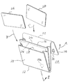
次に添付図面を参照して本発明による非接触型ICカード用ケースの実施例を詳細に説明する。図1を参照すると、本発明の実施例による非接触型IC(集積回路)カード用ケース10は、全体がほぼ直方体の外観を呈する収納体として形成されている。収納体10は、全体が、導電性を有さない材質、たとえば動植物もしくは合成繊維の布、皮革、または天然もしくは合成樹脂などの絶縁材料で、図示の形態に構成されている。これらの材料は、光学的に透明であっても、不透明であってもよい。カード用ケース10は、たとえば財布、定期券入れ、名刺入れなどに有利に適用される。
Embodiments of a non-contact type IC card case according to the present invention will now be described in detail with reference to the accompanying drawings. Referring to FIG. 1, a non-contact type IC (integrated circuit)
収納体10は、全体として本体12および蓋部14で構成されている。本体12は、その中央に、本実施例では、全体として矩形の平板形状を有する間仕切り16を有し、これによって、その平板形状の両主面の側に2つの収納部18および20を画成している。換言すれば、本体12は、収納部18および20の外側を、少なくとも部分的に画成する32をなしている。
The
蓋部14は、図からわかるように、全体として矩形の平面形状を有し、本実施例では、その矩形の一辺22が本体12と一体構造をなしている。これによって、矢印Aの方向に蓋部14を回動させて、収納部16および18を閉じることができる。蓋部14は、必ずしも設ける必要はない。収納部16および18は、通常流通しているSuica(商標)やpasmo(商標)などの非接触型ICカードを収納可能な形状および大きさを有する。非接触型ICカードは一般に、54mm x 86mm程度の平面寸法で、0.5mm程度の厚さを有するので、それらを複数枚、収納できる寸法であれば、十分である。
As can be seen from the figure, the
間仕切り16には、図1に点線24で示すように、全体的に矩形の平面形状を有する導電体シートが含まれている。導電体シート24は、たとえばアルミニウムや銅などの金属材料が有利に適用される。または、合成樹脂シートの、少なくとも一方の主面に、これらの金属を蒸着させたものでのよい。このような導電体シート24によって、その両側に形成されている2つの収納部18および20を互いに電磁的に遮蔽している。両収納部18および20にはそれぞれ、たとえば矢印BおよびC(図1)で示すように非接触型ICカードなどのカード状物品26および28を収納することができる。
As shown by a
たとえば、Suica(商標)などの非接触型ICカードの場合、13.56MHzの短波帯やBluetooth(商標)など産業、科学、医学用機器の周波数帯域、2.40GHzから2.48GHzの電波を使用するものが多い。一般に、このような電磁波は、周波数が高いほど指向性が強く、ほとんど回折することがないのは周知である。したがって、導電体シート24は、ICカードの外形と同程度の平面形状の大きさで、そのような電磁波を十分に遮蔽することができる。
For example, in the case of non-contact type IC cards such as Suica (trademark), those using 13.56MHz short-wave band and frequency bands of industrial, scientific and medical equipment such as Bluetooth (trademark) and radio waves of 2.40GHz to 2.48GHz. Many. In general, it is well known that such electromagnetic waves have higher directivity and hardly diffract as the frequency increases. Therefore, the
図1における一点鎖線矢印IIから見た断面を図2に示す。図2から分かるように、本実施例では、導電体すなわち金属シート24は、間仕切り16の絶縁材料、すなわち本体12の材料で囲繞されている。この囲繞は、導電体シート24をカード状物品26または28などからの物理的接触による損傷から保護するためであり、必ずしも囲繞する必要はない。導電体シート24は、全部または一部が露出していてもよい。囲繞はまた、本体12の材料によらなくてもよい。図2には、導電体シート24を分かりやすく表示するため、その厚さ方向の寸法がいくぶん、誇張されて記載されている。導電体シート24は、このように厚くなく、薄い箔状のもので十分である。
FIG. 2 shows a cross section viewed from the one-dot chain line arrow II in FIG. As can be seen from FIG. 2, in this embodiment, the conductor, that is, the
使用状態において、Suica(商標)やpasmo(商標)など、2枚の非接触型ICカード26および28をそれぞれ1枚、収納部18および20に収納することができる。勿論、非接触型ICカード以外のカード、たとえば磁気ストライプカードなどを同時に収納してもよい。しかし、非接触型ICカード26や28は、本実施例では、それぞれの収納部18および20に各1枚宛て、収納するのがよい。もちろん、収納部18および20のうちのいずれか一方に、ICカード26または28を1枚だけ収納しても、なんら差し支えない。
In the state of use, two non-contact
非接触型ICカード26や28を収納部18および20に各1枚宛て収納することにより、たとえば、一方の非接触型ICカード26、たとえば公費で使用するSuica(商標)を自動改札機(図示せず)で使用したいときは、その入力位置すなわちアンテナ部にその収納部18の側を向けてこれを接触ないし接近させる。自動改札機の入力位置から発した電波は、一方の非接触型ICカード26には適切に到達するが、導電体シート24の存在により他方の非接触型ICカード28には到達しない。したがって、一方の非接触型ICカード26だけが自動改札機によって適切に認識ないし処理される。
By storing one non-contact
他方の非接触型ICカード28、たとえば私費で使用するクレジットカードまたはpasmo(商標)を使用したいときは、それを収納した収納部20の側を識別装置または自動改札機の入力位置すなわちアンテナ部に向けて接触または接近させる。自動改札機の入力位置から発した電波は、他方の非接触型ICカード28に適切に到達する。しかし、やはり導電体シート24の存在により、一方の非接触型ICカード26には、これを検知するに足りる電力レベルの電波が達しない。したがって、他方の非接触型ICカード28だけが識別装置または自動改札機によって適切に認識される。こうして、2枚の非接触型ICカード26および28の適切な使い分け使用が達成される。
If you want to use the other non-contact type IC card 28, for example, a credit card or pasmo (trademark) used for private expenses, place the side of the
このような使い分け使用は、使用者の意図の下に適切に行なわれる必要がある。その目的のため、本実施例では、使用者が2つの収納部18および20を迅速に認識する補助として、表示30が設けられている。表示30は、本実施例では可視表示である。可視表示30は、本実施例の場合、蓋部14を矢印Aの方向に閉じると、一方の収納部18の側に対応する位置32aに来るように、蓋部14の表面に配設されている。本実施例では、可視表示30は、ハート型の記号であるが、これのみに限定されず、他の記号や、A、Bなどの文字、たとえば線、Suica(商標)やpasmo(商標)などのカードを識別する文字やロゴであってもよい。表示30は、可視表示に加えて、またはこれに代わって、もちろん、包囲体32の外側に形成されたエンボス加工などの形状的表示であってもよい。後者はとくに、視覚障害者にとっても利用価値が高い。また、一方の収納部、たとえば18の側に対応する部分だけ、本体12または蓋部14の着色または形状を他の部分と変えてもよい。また、本体12を光学的に透明な材料で形成し、収納物26および28を区別して判別できるように構成してもよい。要は、両収納部18および20を互いに区別して、明瞭に認識できる表示であれば、十分である。
Such proper use needs to be appropriately performed under the intention of the user. For this purpose, in this embodiment, a
本発明は、上述の実施例の特定の形態に限定されない。たとえば、アルミニウムのフォイルやシード、板などの導電体シート24を単体で、複数枚の非接触型ICカードの間に介挿することによっても、それらの使い分け使用が可能である。また、許容されるなら、非接触型ICカードの一方の主面に導電体シートを貼付することによっても、複数枚の非接触型ICカードを使い分けて使用することができる。収納部18および24は、カード26および28をその内部に収容する形態であったが、もちろん個のような特定の形態にのみ限定されず、単にカード26または28を保持する爪などのカード用部材保持手段を有する保持部によっても、本発明の目的は達成される。本発明はもちろん、図示の実施例について説明した鉄道用非接触型ICカードのみに限定されるものではなく、クレジットカードやデビットカード、あるいは社員証や入門証などのなど個人識別(ID)カードなど、あらゆる非接触型ICカードに効果的に適用される。
The present invention is not limited to the specific form of the embodiments described above. For example, the
10 非接触型ICカード用ケース
12 本体
14 蓋部
16 間仕切り
18、20 収納部
24 導電体シート
26、28 非接触型ICカード
10 Case for non-contact type IC card
12 Body
14 Lid
16 partitions
18, 20 compartment
24 Conductor sheet
26, 28 Contactless IC card
Claims (3)
Priority Applications (1)
| Application Number | Priority Date | Filing Date | Title |
|---|---|---|---|
| JP2007078365A JP2008242552A (en) | 2007-03-26 | 2007-03-26 | Case for non-contact type ic card |
Applications Claiming Priority (1)
| Application Number | Priority Date | Filing Date | Title |
|---|---|---|---|
| JP2007078365A JP2008242552A (en) | 2007-03-26 | 2007-03-26 | Case for non-contact type ic card |
Publications (1)
| Publication Number | Publication Date |
|---|---|
| JP2008242552A true JP2008242552A (en) | 2008-10-09 |
Family
ID=39913865
Family Applications (1)
| Application Number | Title | Priority Date | Filing Date |
|---|---|---|---|
| JP2007078365A Withdrawn JP2008242552A (en) | 2007-03-26 | 2007-03-26 | Case for non-contact type ic card |
Country Status (1)
| Country | Link |
|---|---|
| JP (1) | JP2008242552A (en) |
Cited By (1)
| Publication number | Priority date | Publication date | Assignee | Title |
|---|---|---|---|---|
| JP2010176428A (en) * | 2009-01-29 | 2010-08-12 | Minoru Kishimoto | Ic card holder |
-
2007
- 2007-03-26 JP JP2007078365A patent/JP2008242552A/en not_active Withdrawn
Cited By (1)
| Publication number | Priority date | Publication date | Assignee | Title |
|---|---|---|---|---|
| JP2010176428A (en) * | 2009-01-29 | 2010-08-12 | Minoru Kishimoto | Ic card holder |
Similar Documents
| Publication | Publication Date | Title |
|---|---|---|
| US8427317B2 (en) | Apparatus and method to electromagnetically shield portable consumer devices | |
| US8725222B2 (en) | Payment-enabled mobile telephone assembly | |
| US9024763B2 (en) | Arrangement comprising an object made at least partially of metal or precious metal and an RFID identification device | |
| US9960476B2 (en) | Smart card constructions | |
| US9230255B1 (en) | Payment card having light-emitting diode indicators coordinated with stored payment applications | |
| EP1893045A1 (en) | Carrying devices for rf tokens | |
| US8578982B2 (en) | Scanner resistant device for RFID cards | |
| US20170196129A1 (en) | Device for preventing data theft, use of false identity, and fraud during contactless data transmission via electromagnetic radio waves | |
| JP2008242552A (en) | Case for non-contact type ic card | |
| JP2005284862A (en) | IC card holder | |
| JP2009099122A (en) | Non-contact ic card storage tool | |
| US20170032235A1 (en) | Scanner resistant device with built in reading lens and led light | |
| EP4264489B1 (en) | Assembly for shielding at least one radio-frequency chip and method for making the same | |
| JP2006018785A (en) | Mechanism for preventing failure in using ic card and ic tag or the like, and housing case applying same mechanism | |
| JP2005346549A (en) | Non-contact ic card communication preventing device and non-contact ic card case | |
| HK40100685A (en) | Assembly for shielding at least one radio-frequency chip and method for making the same | |
| KR20140050851A (en) | Led luminous wallet with traffic card function | |
| KR101712996B1 (en) | Multi card having a shield cover | |
| JP2009217536A (en) | Contactless ic card | |
| JP2017520040A (en) | Device to prevent data theft, identity fraud, and fraud during contactless data transmission through electromagnetic waves | |
| KR20180093309A (en) | Rf card activation device | |
| KR20110041015A (en) | Card border protector | |
| KR20090002715U (en) | RFID Card which can check information frequently |
Legal Events
| Date | Code | Title | Description |
|---|---|---|---|
| A300 | Withdrawal of application because of no request for examination |
Free format text: JAPANESE INTERMEDIATE CODE: A300 Effective date: 20100601 |