JP2008242995A - Electronic control unit - Google Patents
Electronic control unit Download PDFInfo
- Publication number
- JP2008242995A JP2008242995A JP2007085046A JP2007085046A JP2008242995A JP 2008242995 A JP2008242995 A JP 2008242995A JP 2007085046 A JP2007085046 A JP 2007085046A JP 2007085046 A JP2007085046 A JP 2007085046A JP 2008242995 A JP2008242995 A JP 2008242995A
- Authority
- JP
- Japan
- Prior art keywords
- microcomputer
- mode
- control software
- rewrite
- rewriting
- Prior art date
- Legal status (The legal status is an assumption and is not a legal conclusion. Google has not performed a legal analysis and makes no representation as to the accuracy of the status listed.)
- Granted
Links
Images




Classifications
-
- G—PHYSICS
- G06—COMPUTING OR CALCULATING; COUNTING
- G06F—ELECTRIC DIGITAL DATA PROCESSING
- G06F11/00—Error detection; Error correction; Monitoring
- G06F11/07—Responding to the occurrence of a fault, e.g. fault tolerance
- G06F11/14—Error detection or correction of the data by redundancy in operations
- G06F11/1402—Saving, restoring, recovering or retrying
- G06F11/1415—Saving, restoring, recovering or retrying at system level
- G06F11/1433—Saving, restoring, recovering or retrying at system level during software upgrading
-
- G—PHYSICS
- G06—COMPUTING OR CALCULATING; COUNTING
- G06F—ELECTRIC DIGITAL DATA PROCESSING
- G06F11/00—Error detection; Error correction; Monitoring
- G06F11/07—Responding to the occurrence of a fault, e.g. fault tolerance
- G06F11/0703—Error or fault processing not based on redundancy, i.e. by taking additional measures to deal with the error or fault not making use of redundancy in operation, in hardware, or in data representation
- G06F11/0706—Error or fault processing not based on redundancy, i.e. by taking additional measures to deal with the error or fault not making use of redundancy in operation, in hardware, or in data representation the processing taking place on a specific hardware platform or in a specific software environment
- G06F11/0736—Error or fault processing not based on redundancy, i.e. by taking additional measures to deal with the error or fault not making use of redundancy in operation, in hardware, or in data representation the processing taking place on a specific hardware platform or in a specific software environment in functional embedded systems, i.e. in a data processing system designed as a combination of hardware and software dedicated to performing a certain function
- G06F11/0739—Error or fault processing not based on redundancy, i.e. by taking additional measures to deal with the error or fault not making use of redundancy in operation, in hardware, or in data representation the processing taking place on a specific hardware platform or in a specific software environment in functional embedded systems, i.e. in a data processing system designed as a combination of hardware and software dedicated to performing a certain function in a data processing system embedded in automotive or aircraft systems
-
- G—PHYSICS
- G06—COMPUTING OR CALCULATING; COUNTING
- G06F—ELECTRIC DIGITAL DATA PROCESSING
- G06F8/00—Arrangements for software engineering
- G06F8/60—Software deployment
-
- G—PHYSICS
- G06—COMPUTING OR CALCULATING; COUNTING
- G06F—ELECTRIC DIGITAL DATA PROCESSING
- G06F11/00—Error detection; Error correction; Monitoring
- G06F11/07—Responding to the occurrence of a fault, e.g. fault tolerance
- G06F11/0703—Error or fault processing not based on redundancy, i.e. by taking additional measures to deal with the error or fault not making use of redundancy in operation, in hardware, or in data representation
- G06F11/0751—Error or fault detection not based on redundancy
- G06F11/0754—Error or fault detection not based on redundancy by exceeding limits
- G06F11/0757—Error or fault detection not based on redundancy by exceeding limits by exceeding a time limit, i.e. time-out, e.g. watchdogs
Landscapes
- Engineering & Computer Science (AREA)
- Theoretical Computer Science (AREA)
- General Engineering & Computer Science (AREA)
- Physics & Mathematics (AREA)
- General Physics & Mathematics (AREA)
- Quality & Reliability (AREA)
- Software Systems (AREA)
- Stored Programmes (AREA)
- Control By Computers (AREA)
- Safety Devices In Control Systems (AREA)
Abstract
【課題】制御ソフトが連続して書き換えられる2つのマイコンA,Bのうち、少なくとも後で書き換えが実施される方のマイコンAは常時電源供給される電子制御装置において、各マイコンA、Bの制御ソフトを確実に書き換え可能にする。
【解決手段】マイコンAには、誤って書換モードになった場合の対策として、書換モード時に書換ツールから必要な情報が一定時間以内に送られてこなければ通常モードに戻るタイムアウト機能が設けられている。そこで、両マイコンA,Bを通常モードから離脱させて制御ソフトを書き換える場合、マイコンBは通常モードから書換モードになるが、マイコンAは待機状態となる。そして、マイコンAは、マイコンBの制御ソフトの書き換えが終了して書換ツールからの書換対象切換コマンドを受けると書換モードに移行する。このため、マイコンBの制御ソフトの書き換え中にマイコンAがタイムアウト機能により通常モードに戻ることがない。
【選択図】図9Of the two microcomputers A and B whose control software is continuously rewritten, at least the microcomputer A to be rewritten later is an electronic controller in which power is constantly supplied. Ensure that software can be rewritten.
A microcomputer A is provided with a time-out function for returning to a normal mode if necessary information is not sent from the rewriting tool within a certain time in the rewriting mode as a countermeasure when the rewriting mode is mistakenly entered. Yes. Therefore, when both microcomputers A and B are removed from the normal mode and the control software is rewritten, the microcomputer B changes from the normal mode to the rewrite mode, but the microcomputer A enters a standby state. The microcomputer A shifts to the rewrite mode when the rewrite of the control software of the microcomputer B is completed and the rewrite object switching command is received from the rewrite tool. For this reason, the microcomputer A does not return to the normal mode due to the timeout function while the control software of the microcomputer B is being rewritten.
[Selection] Figure 9
Description
本発明は、複数のマイコン(マイクロコンピュータ)を備えた電子制御装置に関し、特に、その各マイコンの制御ソフトウェアをオンボード書き換え可能な電子制御装置に関するものである。 The present invention relates to an electronic control device including a plurality of microcomputers (microcomputers), and more particularly to an electronic control device that can rewrite control software of each microcomputer on-board.
従来より、自動車用の電子制御装置として、電気的にデータの書き換えが可能なEEPROMやフラッシュメモリなどの不揮発性メモリ(以下、書換可能不揮発性メモリともいう)を有するマイコンを備え、その書換可能不揮発性メモリに格納された制御プログラムや制御データからなる制御ソフトウェアを、市場への供給後でも書き換えることができるようにしたものがある。 2. Description of the Related Art Conventionally, as an electronic control device for an automobile, a microcomputer having a nonvolatile memory (hereinafter also referred to as a rewritable nonvolatile memory) such as an EEPROM or a flash memory capable of electrically rewriting data is provided, and the rewritable nonvolatile memory Some control software including control programs and control data stored in the memory can be rewritten even after being supplied to the market.
即ち、この種の電子制御装置において、マイコンは、通常時には、書換可能不揮発性メモリに格納された制御ソフトウェアを実行することでエンジン等の制御対象を制御するが、当該電子制御装置と通信可能に接続される書換装置からのモード切換指令を受けると、制御ソフトウェアとは別の書換処理用ソフトウェアを実行する書換モードに移行して、書換可能不揮発性メモリ内の制御ソフトウェアを書換装置から送信されて来る制御ソフトウェアに書き換えるための書換処理を行う。 In other words, in this type of electronic control device, the microcomputer normally controls control objects such as an engine by executing control software stored in a rewritable nonvolatile memory, but can communicate with the electronic control device. When a mode switching command is received from the connected rewrite device, the rewrite mode is executed to execute rewrite processing software different from the control software, and the control software in the rewritable nonvolatile memory is transmitted from the rewrite device. Rewrite processing is performed to rewrite the control software.
よって、このような電子制御装置によれば、マイコンを当該装置に実装した状態で、書換可能不揮発性メモリ内の制御ソフトウェアを書き換える、所謂オンボード書き換えが可能となるため、市場への供給後に何等かの原因で動作内容(制御内容)を変更しなければならない事態が起こったとしても、容易に対応することができる。 Therefore, according to such an electronic control device, it is possible to rewrite the control software in the rewritable nonvolatile memory with the microcomputer mounted on the device, so-called on-board rewriting is possible. Even if a situation in which the operation content (control content) has to be changed occurs due to the cause, it can be easily handled.
そして、近年、この種の電子制御装置では、制御内容の複雑化に伴って、複数のマイコンを搭載したものが主流となっており、各マイコンについて、制御ソフトウェアのオンボード書き換えが可能となるように構成することが考えられる(例えば特許文献1,2参照)。 In recent years, electronic control devices of this type are mainly equipped with a plurality of microcomputers as control contents become more complicated, and on-board rewriting of control software is possible for each microcomputer. (For example, refer to Patent Documents 1 and 2).
また、複数のマイコンを搭載した電子制御装置においては、特定のマイコンに他のマイコンを監視する監視機能を持たせる場合もある。つまり、特定のマイコンが、制御ソフトウェアを実行する通常モード時において、監視対象である他のマイコンにて制御ソフトウェアが正常に実行されているか否かを監視し、異常と判断したならば上記他のマイコンをリセットする、といった構成を採る場合がある(例えば特許文献1,2参照)
ところで、複数の各マイコンの制御ソフトウェアをオンボード書き換え可能な電子制御装置においては、各マイコンの制御ソフトウェアを連続して書き換える場合に、各マイコンを1つずつ書換モードにするのではなく、まず書換装置からのモード切換指令により全てのマイコンを書換モードに移行させ、その状態で、各マイコンの制御ソフトウェアを順番に書き換えるように構成することが考えられる。なぜなら、複数のマイコンが情報を共有しながら各自の制御対象を制御する構成の場合に、あるマイコンの制御ソフトウェアを書き換えている最中に他のマイコンを通常モードで動作させても所望の制御を確実に行うことができず、全てのマイコンを通常モードから離脱させる方が好ましいと考えられるか
らである。
By the way, in the electronic control device that can rewrite the control software of each microcomputer on board, when rewriting the control software of each microcomputer continuously, each microcomputer is not first put into the rewrite mode, but rewritten first. It is conceivable that all microcomputers are shifted to the rewrite mode by a mode switching command from the apparatus, and the control software of each microcomputer is rewritten in order in that state. This is because, in the case of a configuration in which a plurality of microcomputers control their own control objects while sharing information, the desired control can be performed even if another microcomputer is operated in the normal mode while the control software of a certain microcomputer is being rewritten. This is because it cannot be performed reliably, and it is considered preferable to remove all the microcomputers from the normal mode.
また特に、この手法は、あるマイコンMaに他のマイコンMbを監視する監視機能を持たせている場合に必要である。つまり、監視する側のマイコンMaを通常モードにしたままで、監視対象であるマイコンMbの制御ソフトウェアの書き換えを実施すると、マイコンMaが前述の監視機能によってマイコンMbをリセットしてしまうからであり、このため、マイコンMa,Mbの両方を通常モードから離脱させて、マイコンMaに備えられた監視機能を無効化する必要があるからである。 In particular, this method is necessary when a certain microcomputer Ma has a monitoring function for monitoring another microcomputer Mb. That is, if rewriting the control software of the microcomputer Mb to be monitored while the monitoring side microcomputer Ma remains in the normal mode, the microcomputer Ma resets the microcomputer Mb by the aforementioned monitoring function. For this reason, it is necessary to deactivate both the microcomputers Ma and Mb from the normal mode and invalidate the monitoring function provided in the microcomputer Ma.
しかし、各マイコンの制御ソフトウェアを連続して書き換える場合に全てのマイコンを書換モードに移行させる手法を、下記(1)及び(2)の2つの条件を満たす電子制御装置に適用すると、制御ソフトウェアの書き換えを正常に実施することができなくなってしまう可能性がある。 However, when the control software for each microcomputer is rewritten continuously, the technique for shifting all the microcomputers to the rewrite mode is applied to an electronic control device that satisfies the following two conditions (1) and (2). There is a possibility that rewriting cannot be performed normally.
(1)少なくとも2つのマイコンA,Bを備えていると共に、その2つのマイコンA,Bの制御ソフトウェアが連続して書き換えられる場合には、マイコンBの方が先に(換言すれば、マイコンAの方が後に)制御ソフトウェアの書き換えが実施される。 (1) When at least two microcomputers A and B are provided and the control software of the two microcomputers A and B is continuously rewritten, the microcomputer B is the first (in other words, the microcomputer A The control software is rewritten later.
(2)マイコンA,Bのうちの少なくともマイコンAは、常時電源が供給されるようになっている。
ここで、上記(1),(2)の条件を満たす電子制御装置の場合になぜ問題が生じるかについて具体的に説明する。
(2) At least the microcomputer A of the microcomputers A and B is always supplied with power.
Here, the reason why a problem occurs in the case of an electronic control device that satisfies the above conditions (1) and (2) will be specifically described.
まず、例えば特許文献1,2に記載の電子制御装置のように、搭載された各マイコンが、車両のイグニッションスイッチのオンに伴い電源が供給されて動作するマイコンであるならば、何らかの原因により、制御ソフトウェアを実行する通常モードから書換モードに誤って移行してしまっても、イグニッションスイッチを一旦オフして再びオンすれば、通常モードに復帰させることができる。
First, as in the electronic control devices described in
これに対して、常時電源が供給されるマイコンでは、イグニッションスイッチのオフ→オンによる通常モードへの復帰ができないため、一般に、誤って書換モードに移行した場合のフェイルセーフ機能として、タイムアウト機能が設けられる。このタイムアウト機能は、書換モード時の書換処理用ソフトウェアが実行されることで実現される機能であり、書換処理を実施するために必要な情報(例えば、予め定められたコマンドや、書き換えるべき新たな制御ソフトウェアを構成するデータ等)が書換装置から一定時間以内に送られてきたか否かを監視して該情報が送られてこなければ通常モードに復帰する、という機能である。 In contrast, microcomputers that are constantly supplied with power cannot return to normal mode by turning the ignition switch from off to on, so in general, a timeout function is provided as a fail-safe function in case of accidental transition to rewrite mode. It is done. This time-out function is a function realized by executing rewrite processing software in the rewrite mode, and information necessary for performing the rewrite process (for example, a predetermined command or a new one to be rewritten). This is a function of monitoring whether or not data constituting the control software has been sent from the rewriting device within a predetermined time and returning to the normal mode if the information is not sent.
このため、上記(1),(2)の条件を満たす電子制御装置の場合、少なくともマイコンAには上記タイムアウト機能が設けられることとなる。
よって、マイコンA,Bの制御ソフトウェアを連続して書き換える場合において、全てのマイコンを書換モードに移行させると、先にマイコンBの制御ソフトウェアを書き換えている間に、書換装置からマイコンAには制御ソフトウェアの書き換えに必要な情報が送信されないため、マイコンAが上記タイムアウト機能によって通常モードに復帰してしまい、その結果、マイコンAの制御ソフトウェアを書き換えることができなくなってしまう。
For this reason, in the case of an electronic control device that satisfies the above conditions (1) and (2), at least the microcomputer A is provided with the time-out function.
Therefore, when the control software of the microcomputers A and B is continuously rewritten, if all the microcomputers are shifted to the rewrite mode, the rewrite device controls the microcomputer A while the control software of the microcomputer B is rewritten first. Since information necessary for rewriting the software is not transmitted, the microcomputer A returns to the normal mode by the timeout function, and as a result, the control software of the microcomputer A cannot be rewritten.
そして更に、マイコンAが通常モード時にマイコンBを監視するようになっているので
あれば、タイムアウト機能によって通常モードに復帰したマイコンAは、先に制御ソフトウェアの書き換えを行っている最中のマイコンBをリセットしてしまうこととなる。このため、マイコンBの制御ソフトウェアも正常に書き換えることができなくなってしまう。
Further, if the microcomputer A is to monitor the microcomputer B during the normal mode, the microcomputer A that has returned to the normal mode by the time-out function is the microcomputer B that is currently rewriting the control software. Will be reset. For this reason, the control software of the microcomputer B cannot be rewritten normally.
本発明は、こうした問題に鑑みなされたものであり、制御ソフトウェアが連続して書き換えられる2つのマイコンのうち、少なくとも後で制御ソフトウェアの書き換えが実施される方のマイコンは常時電源供給されるようになっている電子制御装置において、各マイコンの制御ソフトウェアを確実に書き換え可能にすることを目的としている。 The present invention has been made in view of such a problem, and among the two microcomputers whose control software is continuously rewritten, at least the microcomputer whose control software is to be rewritten later is always supplied with power. The purpose of the electronic control device is to make sure that the control software of each microcomputer can be rewritten.
請求項1の電子制御装置は、外部装置と通信可能に接続される第1マイコン及び第2マイコンを備えている。そして、第1マイコン及び第2マイコンの各々は、電気的にデータの書き換えが可能な不揮発性メモリ(書換可能不揮発性メモリ)を有すると共に、通常モード時には、その不揮発性メモリに格納された制御ソフトウェアを実行することで制御対象を制御し、外部装置からのモード切換指令を受けた場合には、制御ソフトウェアとは別の書換処理用ソフトウェアを実行する書換モードに移行して、その書換処理用ソフトウェアを実行することにより、書換可能不揮発性メモリ内の制御ソフトウェアを外部装置から送信されて来る制御ソフトウェアに書き替えるための書換処理を行うようになっている。 According to another aspect of the present invention, an electronic control device includes a first microcomputer and a second microcomputer that are communicably connected to an external device. Each of the first microcomputer and the second microcomputer has a nonvolatile memory (rewritable nonvolatile memory) in which data can be electrically rewritten, and control software stored in the nonvolatile memory in the normal mode. When the control target is controlled by executing the command and a mode switching command is received from an external device, the rewrite processing software for executing the rewrite processing software different from the control software is transferred to the rewrite processing software. By executing the above, the rewriting process for rewriting the control software in the rewritable nonvolatile memory with the control software transmitted from the external device is performed.
また、請求項1の電子制御装置において、第1マイコンと第2マイコンの制御ソフトウェアが連続して書き換えられる場合には、外部装置から各マイコンへ前記モード切換指令が送信されると共に、第2マイコンの方が先に(換言すれば、第1マイコンの方が後に)制御ソフトウェアの書き換えが実施されるようになっている。 In the electronic control device according to claim 1, when the control software of the first microcomputer and the second microcomputer is continuously rewritten, the mode switching command is transmitted from the external device to each microcomputer, and the second microcomputer The control software is rewritten first (in other words, the first microcomputer is later).
そして更に、2つのマイコンのうち、少なくとも第1マイコンは、常時電源が供給されるようになっており、その第1マイコンが実行する書換処理用ソフトウェアには、当該第1マイコンにおいて前記書換処理を実施するために必要な所定の情報が外部装置から当該第1マイコンへ一定時間以内に送られてきたか否かを監視し該情報が送られてこなければ制御ソフトウェアを実行する通常モードに復帰するタイムアウト機能を、当該第1マイコンに実現させるプログラムが含まれている。つまり、常時電源が供給されると共に、第2マイコンの後で制御ソフトウェアの書き換えが行われる第1マイコンは、書換モードの場合にタイムアウト機能を有することとなる。 Further, at least the first microcomputer of the two microcomputers is always supplied with power, and the rewriting process software executed by the first microcomputer includes the rewriting process in the first microcomputer. A time-out for returning to the normal mode in which the control software is executed if it is monitored whether predetermined information necessary for execution is sent from the external device to the first microcomputer within a predetermined time. A program for causing the first microcomputer to realize the function is included. That is, the first microcomputer to which power is constantly supplied and the control software is rewritten after the second microcomputer has a time-out function in the rewrite mode.
そこで特に、請求項1の電子制御装置において、第1マイコンは、外部装置からのモード切換指令を受けた場合に、そのまま書換モードに移行するのではなく、制御ソフトウェアを実行せずに書換モードへ移行するのを待つ待機状態となり、その後、外部装置からのモード移行許可指令を受けると、書換モードに移行するようになっている。 Therefore, in particular, in the electronic control device according to claim 1, when the first microcomputer receives a mode switching command from an external device, the first microcomputer does not shift to the rewriting mode as it is, but enters the rewriting mode without executing the control software. When a transition is made to a standby state waiting for a transition, and then a mode transition permission command is received from an external device, a transition is made to the rewrite mode.
このような電子制御装置において、第1マイコンと第2マイコンの制御ソフトウェアを書き換える場合には、まず、外部装置から各マイコンへモード切換指令を送信する。
すると、第2マイコンは通常モードから書換モードに移行し、第1マイコンは通常モードから抜けて待機状態となる。
In such an electronic control device, when rewriting the control software of the first microcomputer and the second microcomputer, first, a mode switching command is transmitted from the external device to each microcomputer.
Then, the second microcomputer shifts from the normal mode to the rewrite mode, and the first microcomputer leaves the normal mode and enters a standby state.
その後、外部装置から第2マイコン用の制御ソフトウェアを送信すると、第2マイコンが、書換処理により、自己の書換可能不揮発性メモリに格納されている制御ソフトウェアを、その外部装置からの制御ソフトウェアに書き換えることとなる。 Thereafter, when the control software for the second microcomputer is transmitted from the external device, the second microcomputer rewrites the control software stored in its own rewritable nonvolatile memory with the control software from the external device by rewriting processing. It will be.
そして、第2マイコンの制御ソフトウェアの書き換えが終了した後、外部装置から第1マイコンへモード移行許可指令を送信すれば、第1マイコンを書換モードに移行させるこ
とができる。よって、その後、外部装置から第1マイコン用の制御ソフトウェアを送信することにより、第1マイコンの制御ソフトウェアを書き換えることができる。
Then, after the rewriting of the control software of the second microcomputer is completed, the first microcomputer can be shifted to the rewriting mode by transmitting a mode shift permission command from the external device to the first microcomputer. Therefore, thereafter, the control software for the first microcomputer can be rewritten by transmitting the control software for the first microcomputer from the external device.
ここで特に、第1マイコンは、第2マイコンの制御ソフトウェアの書き換えが行われている最中に、制御ソフトウェアを実行しないが書換モードにも移行しない(即ち、書換処理用ソフトウェアも実行しない)待機状態となるため、タイムアウト機能によって通常モードに復帰してしまうことはない。このため、第2マイコンに続いて、第1マイコンの制御ソフトウェアも確実に書き換えることができるようになる。 In particular, the first microcomputer does not execute the control software but does not enter the rewrite mode (that is, does not execute the rewrite processing software) while the control software of the second microcomputer is being rewritten. Therefore, the time-out function does not return to the normal mode. Therefore, the control software of the first microcomputer can be surely rewritten following the second microcomputer.
このように、請求項1の電子制御装置によれば、第2マイコンの制御ソフトウェアと第1マイコンの制御ソフトウェアを、その順に連続して書き換える場合に、その両方のマイコンを通常モードから離脱させても、第2マイコンの制御ソフトウェアを書き換えている最中に第1マイコンがタイムアウト機能によって通常モードに復帰してしまうことが防止され、各マイコンの制御ソフトウェアを確実に書き換えることができるようになる。 Thus, according to the electronic control device of claim 1, when the control software of the second microcomputer and the control software of the first microcomputer are rewritten successively in that order, both the microcomputers are removed from the normal mode. However, while the control software of the second microcomputer is being rewritten, the first microcomputer is prevented from returning to the normal mode by the time-out function, and the control software of each microcomputer can be rewritten securely.
次に、請求項2の電子制御装置では、請求項1の電子制御装置において、第1マイコンが実行する制御ソフトウェアには、第2マイコンにて該第2マイコンの書換可能不揮発性メモリに格納されている制御ソフトウェアが正常に実行されているか否かを監視すると共に、その制御ソフトウェアが正常に実行されていないと判断すると第2マイコンをリセットするための動作を行う監視機能を、第1マイコンに実現させるプログラムが含まれている。つまり、第1マイコンは通常モード時に第2マイコンを監視して異常と判断すると第2マイコンをリセットするようになっている。
Next, in the electronic control device according to
このような請求項2の電子制御装置によれば、第2マイコンの制御ソフトウェアの書き換えが行われている最中に、第1マイコンを通常モードから離脱した待機状態にして、その第1マイコンの第2マイコンに対する監視機能を無効化することができ、そのため、第1マイコンが第2マイコンをリセットしてしまうことを防止することができる。そして、前述したように、第2マイコンの制御ソフトウェアの書き換えが行われている最中に、第1マイコンがタイムアウト機能によって通常モードに復帰してしまうこともない。 According to such an electronic control device of the second aspect, while the control software of the second microcomputer is being rewritten, the first microcomputer is placed in a standby state in which it is removed from the normal mode, and the first microcomputer The monitoring function for the second microcomputer can be invalidated, and therefore the first microcomputer can be prevented from resetting the second microcomputer. As described above, the first microcomputer does not return to the normal mode by the time-out function while the control software of the second microcomputer is being rewritten.
このため、第1マイコンが通常モード時に第2マイコンを監視することと、その各マイコンの制御ソフトウェアを確実に書き換え可能にすることとを両立させることができる。
次に、請求項3の電子制御装置では、請求項2の電子制御装置において、第1マイコンは、制御ソフトウェアを書き換えるための書換処理が終了すると通常モードに復帰するようになっている。そして、第2マイコンは、書換処理が終了すると、制御ソフトウェアを実行しない無制御状態となり、その後、第1マイコンの監視機能によりリセットされることで通常モードに復帰する。つまり、書換処理が終了した第2マイコンは、その後に通常モードへと復帰した第1マイコンの監視機能によりリセットされて通常モードに戻る。
For this reason, both the monitoring of the second microcomputer in the normal mode by the first microcomputer and the reliable rewriting of the control software of each microcomputer can be achieved.
Next, according to a third aspect of the present invention, in the electronic control device according to the second aspect, the first microcomputer returns to the normal mode when the rewriting process for rewriting the control software is completed. When the rewriting process ends, the second microcomputer enters a non-control state in which the control software is not executed, and thereafter returns to the normal mode by being reset by the monitoring function of the first microcomputer. That is, the second microcomputer that has completed the rewriting process is reset by the monitoring function of the first microcomputer that has returned to the normal mode and then returns to the normal mode.
この構成によれば、2つのマイコンを自動的に且つほぼ同時に通常モードへと復帰させることができ、2つのマイコンによる制御開始の同期化が容易となる。また、第1マイコンの第2マイコンに対する監視機能の他に、例えば、第2マイコンが通常モード時に第1マイコンが正常か否かの異常検出を行うようになっている場合に、両マイコンの通常モードへの復帰タイミングが大きく異なると、その第2マイコンの異常検出機能によって異常と判定されてしまう可能性があるが、そのような不都合を防止することができる。 According to this configuration, the two microcomputers can be automatically and almost simultaneously returned to the normal mode, and the control start by the two microcomputers can be easily synchronized. In addition to the monitoring function of the first microcomputer with respect to the second microcomputer, for example, when the second microcomputer detects whether the first microcomputer is normal or not in the normal mode, If the return timing to the mode is greatly different, there is a possibility that the abnormality detection function of the second microcomputer may determine that there is an abnormality, but such inconvenience can be prevented.
次に、請求項4の電子制御装置では、請求項1〜3の電子制御装置において、前記モード移行許可指令は、外部装置が制御ソフトウェアの書換対象を第1マイコン以外のマイコンから第1マイコンに切り換える場合に送信する書換対象切換指令である。 Next, according to a fourth aspect of the present invention, in the electronic control device according to the first to third aspects, the mode transition permission instruction is sent from the microcomputer other than the first microcomputer to the first microcomputer. This is a rewrite target switching command to be transmitted when switching.
つまり、第2マイコンの制御ソフトウェアと第1マイコンの制御ソフトウェアを、その順に連続して書き換える場合、外部装置は、第2マイコンの制御ソフトウェアの書き換えが終了すると、第1マイコンへ、制御ソフトウェアの書換対象を第1マイコンに切り換えることを示す書換対象切換指令を送信するように構成されると考えられるため、その書換対象切換指令を、モード移行許可指令として用いている。そして、この構成によれば、外部装置から送信される指令を新たに設ける必要がないという点で有利である。 In other words, when the control software of the second microcomputer and the control software of the first microcomputer are continuously rewritten in that order, the external device rewrites the control software to the first microcomputer when the rewriting of the control software of the second microcomputer is completed. Since it is considered to be configured to transmit a rewrite target switching command indicating that the target is switched to the first microcomputer, the rewrite target switching command is used as a mode transition permission command. This configuration is advantageous in that it is not necessary to newly provide a command transmitted from the external device.
次に、請求項5の電子制御装置では、請求項1〜4の電子制御装置において、第1マイコンは、前記待機状態となっている場合に、特定の復帰条件が成立したか否かを判定し、その復帰条件が成立したと判定すると、通常モードに復帰するようになっている。
Next, in the electronic control device according to
この構成によれば、第1マイコンと第2マイコンとのうち、第2マイコンの制御ソフトウェアだけを書き換える場合にも対応することができる。つまり、外部装置から各マイコンへモード切換指令を送信し、その後、第2マイコンの制御ソフトウェアの書き換えが終了した時点で、上記特定の復帰条件を成立させれば、第1マイコンを待機状態からそのまま通常モードに復帰させることができる。そして、第2マイコンの制御ソフトウェアだけを書き換えたい場合に、その作業を速やかに完了することができる。 According to this configuration, it is possible to cope with a case where only the control software of the second microcomputer is rewritten out of the first microcomputer and the second microcomputer. That is, when a mode switching command is transmitted from the external device to each microcomputer and then the rewriting of the control software of the second microcomputer is completed, if the specific return condition is satisfied, the first microcomputer is left in the standby state as it is. The normal mode can be restored. If only the control software of the second microcomputer is to be rewritten, the operation can be completed promptly.
尚、請求項3に従属する請求項5の電子制御装置ならば、第2マイコンの制御ソフトウェアだけを書き換える場合においても、上記特定の復帰条件を成立させて第1マイコンを通常モードに復帰させると、その第1マイコンの監視機能によって第2マイコンがリセットされて通常モードに復帰することとなる。
In the electronic control device according to
次に、請求項6の電子制御装置では、請求項5の電子制御装置において、第1マイコンは、前記待機状態となっている場合に、外部装置から、制御ソフトウェアの書き換えが終了したことを示す終了通知が送信されてきたか否かを判定し、その終了通知が送信されてきたならば、前記復帰条件が成立したとして通常モードに復帰する。
Next, in the electronic control device according to claim 6, in the electronic control device according to
つまり、一般に、電子制御装置における制御ソフトウェアを書き換えるための外部装置は、制御ソフトウェアを書き換えるための一連の処理を終了する際に、終了通知を送信するようになっているため、「外部装置から終了通知が送信されてきた」ということを、復帰条件としている。そして、この構成によれば、復帰条件としての特別なトリガを追加することなく、待機状態の第1マイコンを通常モードに復帰させることができる。 In other words, in general, an external device for rewriting control software in an electronic control device is configured to send an end notification when completing a series of processes for rewriting control software. “The notification has been sent” is set as a return condition. According to this configuration, the first microcomputer in the standby state can be returned to the normal mode without adding a special trigger as a return condition.
次に、請求項7の電子制御装置では、請求項5,6の電子制御装置において、第1マイコンは、前記待機状態となっている場合に、特定の操作部が操作されたか否かを判定し、その操作部が操作されたならば、前記復帰条件が成立したとして通常モードに復帰するようになっている。 Next, in the electronic control device according to a seventh aspect, in the electronic control device according to the fifth or sixth aspect, the first microcomputer determines whether or not a specific operation unit is operated when the first microcomputer is in the standby state. If the operation unit is operated, the normal mode is restored because the return condition is satisfied.
この構成によれば、前述した効果の他に、例えば第1マイコンが何らかの原因で誤って待機状態になってしまっても、特定の操作部を操作することにより、第1マイコンを強制的に通常モードへと復帰させることができる、という利点がある。 According to this configuration, in addition to the above-described effects, for example, even if the first microcomputer is accidentally put into a standby state for some reason, the first microcomputer is forcibly set to normal by operating a specific operation unit. There is an advantage that it can be returned to the mode.
次に、請求項8の電子制御装置では、請求項1〜7の電子制御装置において、第1マイコンは、前記待機状態となっている場合に、当該第1マイコンが該待機状態であるならばアクティブレベルとなるはずの信号をモニタし、その信号がアクティブレベルでなければ通常モードに復帰するようになっている。 Next, in the electronic control device according to claim 8, in the electronic control device according to claims 1 to 7, if the first microcomputer is in the standby state when the first microcomputer is in the standby state, A signal that should be an active level is monitored, and if the signal is not an active level, the normal mode is restored.
この構成によれば、第1マイコンが何らかの原因で誤って待機状態になってしまっても
、そのような場合にはモニタ対象の信号が非アクティブレベルであるため、第1マイコンを自動的に通常モードへと復帰させることができる。
According to this configuration, even if the first microcomputer accidentally enters a standby state for some reason, the monitor target signal is in an inactive level in such a case. You can return to mode.
以下に、本発明が適用された実施形態の電子制御装置について説明する。尚、本実施形態の電子制御装置は、自動車(車両)に搭載される車載電子制御装置である。
まず図1に示すように、本実施形態の電子制御装置(以下、ECUという)1は、マイコンAとマイコンBを備えている。
Hereinafter, an electronic control device according to an embodiment to which the present invention is applied will be described. In addition, the electronic control apparatus of this embodiment is a vehicle-mounted electronic control apparatus mounted in a motor vehicle (vehicle).
First, as shown in FIG. 1, an electronic control device (hereinafter referred to as ECU) 1 of the present embodiment includes a microcomputer A and a microcomputer B.
マイコンAは、例えば他のECUに対する電源供給制御や常時動作すべき車載機器の制御を行うマイコンであり、常時供給される電源電圧Vaを受けて動作する。
マイコンBは、例えばエンジンを制御するマイコンであり、自動車のイグニッションスイッチがオンされている場合に供給される電源電圧Vbを受けて動作する。
The microcomputer A is, for example, a microcomputer that performs power supply control to other ECUs and controls in-vehicle devices that should always operate, and operates by receiving a power supply voltage Va that is always supplied.
The microcomputer B is a microcomputer for controlling the engine, for example, and operates by receiving the power supply voltage Vb supplied when the ignition switch of the automobile is turned on.
また、ECU1は、車両に配設された車両内通信線2に接続されている。そして、ECU1には、車両内通信線2に接続された他の装置とマイコンA,Bの各々が通信するための通信ドライバ3,5も備えられている。
The ECU 1 is connected to an in-
更に、マイコンA,Bで実行されるソフトウェア(以下単にソフトという)を書き換える際には、車両内通信線2に、外部装置としての書換ツール7がコネクタ9を介して接続される。そして、マイコンA,Bは、通信ドライバ3,5を介して書換ツール7と通信することとなる。尚、図示は省略しているが、書換ツール7もマイコンを主要部として構成されており、通信ドライバ等も備えている。
Furthermore, when rewriting software (hereinafter simply referred to as software) executed by the microcomputers A and B, a rewriting tool 7 as an external device is connected to the in-
次に、マイコンA,Bの構成について説明する。
マイコンAには、データの書き換えが不能なROM11と、データの書き換えが可能な書換可能不揮発性メモリとしてのフラッシュメモリ13と、ROM11及びフラッシュメモリ13に格納されているソフトを実行するコア15とが備えられている。
Next, the configuration of the microcomputers A and B will be described.
The microcomputer A includes a
同様に、マイコンBにも、データの書き換えが不能なROM21と、フラッシュメモリ23と、ROM21及びフラッシュメモリ23に格納されているソフトを実行するコア25とが備えられている。
Similarly, the microcomputer B also includes a
また、マイコンAの方には、コア15がソフトを正常に実行しているか否かを監視するためのウォッチドッグタイマ(以下、WDTと記す)17が内蔵されている。このWDT17は、自己のタイマ値がコア15によって規定時間Ta以内にクリアされなければ異常と判断してコア15をリセットする、という周知のものである。
The microcomputer A has a built-in watchdog timer (hereinafter referred to as WDT) 17 for monitoring whether or not the core 15 is executing software normally. This WDT 17 is a well-known one in which if the timer value is not cleared by the
ここで、マイコンBのフラッシュメモリ23には、エンジンを制御するための制御ソフトを含んだアプリケーションソフトが格納されている。そして、マイコンBは、フラッシュメモリ23内の制御ソフトをコア25によって実行することにより、マイコンAと内部通信線10を介して規定時間Tb1毎に通信しながらエンジンを制御すると共に、マイコンAへ規定時間Tb2以内毎にウォッチドッグパルスWDPを出力する。
Here, the
また、マイコンAのフラッシュメモリ13には、他のECUに対する電源供給制御や常時動作すべき車載機器の制御を行うための制御ソフトを含んだアプリケーションソフトが格納されている。そして、マイコンAは、フラッシュメモリ13内の制御ソフトをコア1
5によって実行することにより、マイコンBと内部通信線10を介して通信しながら他ECUへの電源供給制御や車載機器制御を行うと共に、WDT17を規定時間Ta以内毎にクリアし、更に、マイコンBの動作を監視するための図2の如き監視処理を一定時間毎に繰り返し行う。つまり、マイコンAは内蔵のWDT17によって監視されるが、マイコンBはマイコンAによって監視されるようになっており、そのため、マイコンAが実行する制御ソフトには、図2の監視処理を行うためのプログラムが含まれている。
The
5, while performing communication with the microcomputer B via the
その監視処理の内容を説明すると、図2に示すように、まずS110にて、マイコンBからのウォッチドッグパルスWDPの出力周期が規定時間Tb2以内であるか否かを判定し、出力周期が規定時間Tb2以内であれば、次のS120にて、マイコンBから内部通信線10を介して規定時間Tb1以内に信号が送られてきたか否か(内部通信の周期がOKであるか否か)を判定する。そして、規定時間Tb1以内に信号が送られてきていれば、そのまま当該監視処理を終了する。
The contents of the monitoring process will be described. As shown in FIG. 2, first, in S110, it is determined whether or not the output period of the watchdog pulse WDP from the microcomputer B is within the specified time Tb2, and the output period is specified. If it is within the time Tb2, whether or not a signal is sent from the microcomputer B via the
また、S110にて、マイコンBからのウォッチドッグパルスWDPの出力周期が規定時間Tb2以内ではないと判定した場合、或いは、S120にて、マイコンBから内部通信線10を介して規定時間Tb1以内に信号が送られてこなかったと判定した場合には、S130に移行して、異常カウンタをカウントアップさせる。そして、続くS140にて、異常カウンタの値が異常判定閾値以上になったか否かを判定し、異常判定閾値以上になっていなければ、当該監視処理を終了する。
In S110, when it is determined that the output period of the watchdog pulse WDP from the microcomputer B is not within the specified time Tb2, or in S120, the microcomputer B transmits the
これに対し、S140にて、異常カウンタの値が異常判定閾値以上になったと判定したならば、マイコンBにて制御ソフトが正常に実行されていないと判断して、S150に進み、マイコンBのコア25をリセットするためのリセット信号を出力した後、当該監視処理を終了する。
On the other hand, if it is determined in S140 that the value of the abnormality counter is equal to or greater than the abnormality determination threshold value, the microcomputer B determines that the control software is not normally executed, and proceeds to S150. After outputting a reset signal for resetting the
一方、マイコンBのROM21には、フラッシュメモリ23内のソフトを書換ツール7から送信されて来る新たなソフトに書き替えるための書換処理用ソフトが格納されている。同様に、マイコンAのROM11には、フラッシュメモリ13内のソフトを書換ツール7から送信されて来る新たなソフトに書き替えるための書換処理用ソフトが格納されている。
On the other hand, the
また、図1に示すように、ECU1には、マイコンAから後述するタイミングで出力される書込許可判定信号と、マイコンBから後述するタイミングで出力される書込許可判定信号との論理和をとり、その論理和信号を書込許可信号として出力するオア回路31が設けられている。そして、そのオア回路31からの書込許可信号はマイコンA,Bの各々に入力されるようになっている。
As shown in FIG. 1, the ECU 1 performs a logical sum of a write permission determination signal output from the microcomputer A at a later-described timing and a write permission determination signal output from the microcomputer B at a later-described timing. An OR
更に、マイコンAには、イグニッションスイッチがオンされた場合にアクティブレベルとなるイグニッションスイッチ信号が、外部スイッチ信号の一つとして入力されるようになっている。 Further, an ignition switch signal that becomes an active level when the ignition switch is turned on is input to the microcomputer A as one of the external switch signals.
次に、書換ツール7が実行する処理と、ECU1の各マイコンA,Bが実行する処理について、図3〜図8のフローチャートを用い説明する。
尚、以下の説明において、例えば信号A、通信A、ソフトA、コマンドAなど、「A」が末尾に付されたマイコンA以外のものは、それがマイコンAに対応するものであることを意味している。同様に、例えば信号B、通信B、ソフトB、コマンドBなど、「B」が末尾に付されたマイコンB以外のものは、そのれがマイコンBに対応するものであることを意味している。
Next, processing executed by the rewriting tool 7 and processing executed by the microcomputers A and B of the ECU 1 will be described with reference to the flowcharts of FIGS.
In the following description, for example, signal A, communication A, software A, command A, and the like other than the microcomputer A with “A” added to the end means that it corresponds to the microcomputer A. is doing. Similarly, for example, signal B, communication B, software B, command B, and the like other than the microcomputer B suffixed with “B” means that it corresponds to the microcomputer B. .
まず図3は、書換ツール7が実行する書換処理を表すフローチャートである。尚、図3の処理は、実際には書換ツール7に備えられたマイコンによって実行される。
書換ツール7は、作業者によって車両内通信線2に接続された後に、マイコンA,Bの制御ソフトを書き換えるための特定の操作が行われると、図3の書換処理を開始する。
First, FIG. 3 is a flowchart showing a rewriting process executed by the rewriting tool 7. 3 is actually executed by a microcomputer provided in the rewriting tool 7.
The rewriting tool 7 starts the rewriting process of FIG. 3 when a specific operation for rewriting the control software of the microcomputers A and B is performed after being connected to the in-
そして、まずS200にて、マイコンAとセキュリティ通信Aを行い、次のS210にて、マイコンBとセキュリティ通信Bを行う。
尚、セキュリティ通信A,Bの各々は、マイコンA,Bと特定の情報をやり取りすることで、マイコンA,B側のセキュリティを解除するための通信である。そして、マイコンA,Bの各々は、セキュリティが解除されることで、書換ツール7からのモード切換コマンドA,Bを受付可能な状態となる。また、モード切換コマンドA,Bとは、マイコンA,Bの動作モードを、制御ソフトを実行する通常モードから書換処理用ソフトを実行する書換モードへと移行させるためのコマンドである。
First, in S200, the security communication A is performed with the microcomputer A, and the security communication B is performed with the microcomputer B in the next S210.
Each of the security communications A and B is communication for releasing the security on the microcomputer A and B side by exchanging specific information with the microcomputers A and B. Each of the microcomputers A and B is in a state where it can accept the mode switching commands A and B from the rewriting tool 7 by releasing the security. The mode switching commands A and B are commands for shifting the operation mode of the microcomputers A and B from the normal mode for executing the control software to the rewriting mode for executing the rewriting processing software.
次に、書換ツール7は、S220にて、マイコンAと書換モード移行通信Aを行い、次のS230にて、マイコンBと書換モード移行通信Bを行う。
尚、書換モード移行通信A,Bの各々は、最初にモード切換コマンドA,Bを送信し、その後、マイコンA,Bと特定の情報をやり取りすることで、マイコンA,Bを書換モードに移行させるための通信である。
Next, the rewriting tool 7 performs the rewriting mode transition communication A with the microcomputer A in S220, and performs the rewriting mode transition communication B with the microcomputer B in the next S230.
Each of the rewrite mode transition communications A and B first transmits the mode switching commands A and B, and then exchanges specific information with the microcomputers A and B, thereby shifting the microcomputers A and B to the rewrite mode. Communication.
次に、書換ツール7は、S240にて、マイコンBと初期通信Bを行い、次のS250にて、マイコンBとデータ通信Bを行う。
尚、初期通信Bは、書換モードに移行したマイコンBに対して、フラッシュメモリ23内のソフトを書き換える準備を行わせるための通信であり、例えば、この初期通信Bにより、フラッシュメモリ23におけるソフトの書換領域を指示する。そして、データ通信Bは、書き換えるべき新制御ソフトBを所定データ量毎に順次送信して、マイコンBにフラッシュメモリ23内の既存の制御ソフトBをその新制御ソフトBに書き換えさせるための通信である。
Next, the rewriting tool 7 performs initial communication B with the microcomputer B in S240, and performs data communication B with the microcomputer B in the next S250.
The initial communication B is communication for causing the microcomputer B that has shifted to the rewrite mode to prepare for rewriting the software in the
そして、S250のデータ通信Bが終了すると(即ち、マイコンBの制御ソフトの書き換えが終了すると)、次のS260にて、マイコンAへ書換対象切換コマンドを送信する。すると、後述するように、マイコンAは、この時点で、本当に書換モードへ移行することとなる。尚、マイコンAへの書換対象切換コマンドは、ソフトの書換対象をマイコンA以外のマイコンからマイコンAに切り換えることを示すコマンドである。 When the data communication B in S250 ends (that is, when the rewriting of the control software of the microcomputer B ends), a rewrite target switching command is transmitted to the microcomputer A in the next S260. Then, as will be described later, the microcomputer A really shifts to the rewrite mode at this point. The rewrite target switching command to the microcomputer A is a command indicating that the software rewrite target is switched from a microcomputer other than the microcomputer A to the microcomputer A.
次に、書換ツール7は、S270にて、マイコンAと初期通信Aを行い、次のS280にて、マイコンAとデータ通信Aを行う。
尚、初期通信Aとデータ通信Aは、前述した初期通信B及びデータ通信Bと同じ役割の通信である。即ち、初期通信Aは、書換モードに移行したマイコンAに対して、フラッシュメモリ13内のソフトを書き換える準備を行わせるための通信であり、例えば、この初期通信Aにより、フラッシュメモリ13におけるソフトの書換領域を指示する。そして、データ通信Aは、書き換えるべき新制御ソフトAを所定データ量毎に順次送信して、マイコンAにフラッシュメモリ13内の既存の制御ソフトAをその新制御ソフトAに書き換えさせるための通信である。
Next, the rewriting tool 7 performs initial communication A with the microcomputer A in S270, and performs data communication A with the microcomputer A in next S280.
The initial communication A and the data communication A are communications having the same role as the initial communication B and the data communication B described above. That is, the initial communication A is communication for making the microcomputer A that has shifted to the rewrite mode prepare to rewrite the software in the
そして、S280のデータ通信Aが終了すると(即ち、マイコンAの制御ソフトの書き換えが終了すると)、次のS290にて、マイコンA,Bの両方へ終了通知コマンドを送信し、その後、当該書換処理を終了する。尚、終了通知コマンドは、ソフトの書き換えが終了したことを示すコマンドである。 When the data communication A in S280 is completed (that is, when the rewriting of the control software of the microcomputer A is completed), an end notification command is transmitted to both the microcomputers A and B in the next S290, and then the rewriting process is performed. Exit. The end notification command is a command indicating that software rewriting has ended.
次に図4は、マイコンBが実行する処理を表すフローチャートである。そして、図4において、S300の処理がフラッシュメモリ23内の制御ソフトBによって実現され、S310〜S370の処理がフラッシュメモリ23内の制御ソフトB以外のアプリケーションソフトBによって実現され、S380,S390の処理がROM21内の書換処理用ソフトBによって実現される。
Next, FIG. 4 is a flowchart showing processing executed by the microcomputer B. In FIG. 4, the process of S300 is realized by the control software B in the
図4に示すように、マイコンBは、初期状態から動作を開始すると、フラッシュメモリ23に格納されている制御ソフトBを実行することにより、通常の制御処理を行う(S300)。尚、前述したように、マイコンBは、この制御ソフトBによる制御処理により、マイコンAと内部通信線10を介して規定時間Tb1毎に通信しながらエンジンを制御すると共に、マイコンAへ規定時間Tb2以内毎にウォッチドッグパルスWDPを出力する。
As shown in FIG. 4, when the microcomputer B starts its operation from the initial state, the microcomputer B performs the normal control process by executing the control software B stored in the flash memory 23 (S300). As described above, the microcomputer B controls the engine while communicating with the microcomputer A via the
そして、マイコンBは、その制御処理を行っている最中に、書換ツール7からのセキュリティ通信Bの信号を受信したか否かを判定し(S310)、セキュリティ通信Bの信号を受信しなければ、制御処理を続ける(S310:NO→S300)。この状態が、通常モードの状態である。 Then, the microcomputer B determines whether or not the security communication B signal is received from the rewriting tool 7 during the control process (S310), and if the security communication B signal is not received. The control process is continued (S310: NO → S300). This state is a normal mode state.
一方、書換ツール7からのセキュリティ通信Bの信号を受信したならば(S310:YES)、S320に移行して、引き続き書換ツール7とのセキュリティ通信Bを行い、次のS330にて、セキュリティを解除して良いか否かを判定する。具体的には、書換ツール7とのセキュリティ通信Bが規定の手順で全て完了できたならば、セキュリティを解除して良いと判定する。 On the other hand, if the security communication B signal is received from the rewriting tool 7 (S310: YES), the process proceeds to S320, and security communication B is continuously performed with the rewriting tool 7, and the security is released in the next S330. Judge whether or not to do so. Specifically, if the security communication B with the rewriting tool 7 has been completed in accordance with a prescribed procedure, it is determined that the security can be canceled.
そして、セキュリティを解除して良いと判定しなかった場合には、S300に戻って再び制御ソフトBによる制御処理を行うが、セキュリティを解除して良いと判定した場合には、S340に進む。 If it is not determined that the security can be released, the process returns to S300 and the control process by the control software B is performed again. If it is determined that the security can be released, the process proceeds to S340.
S340では、S330にてセキュリティを解除して良いと判定してから一定時間以内に書換ツール7からのモード切換コマンドBを受信したか否かを判定する。そして、一定時間内にモード切換コマンドBを受信しなければ、S300に戻って再び制御ソフトBによる制御処理を行うが、一定時間以内にモード切換コマンドBを受信したならば、S350に進んで、書換ツール7との書換モード移行通信Bを行う。 In S340, it is determined whether or not the mode switching command B from the rewriting tool 7 is received within a predetermined time after it is determined in S330 that the security can be canceled. If the mode switching command B is not received within a predetermined time, the process returns to S300 and the control process is performed again by the control software B. If the mode switching command B is received within the predetermined time, the process proceeds to S350. Rewrite mode transition communication B with the rewrite tool 7 is performed.
次にS360にて、書換モードに移行して良いか否かを判定する。具体的には、書換ツール7との書換モード移行通信Bが規定の手順で全て完了できたならば、書換モードに移行して良いと判定する。そして、書換モードに移行して良いと判定しなかった場合には、S300に戻って再び制御ソフトによる制御処理を行うが、書換モードに移行して良いと判定した場合には、S370に進む。 Next, in S360, it is determined whether or not it is possible to shift to the rewrite mode. Specifically, if the rewrite mode transition communication B with the rewrite tool 7 has been completed in accordance with a prescribed procedure, it is determined that the rewrite mode can be shifted. If it is not determined that the mode can be changed to the rewrite mode, the process returns to S300 and the control process using the control software is performed again. If it is determined that the mode can be changed to the rewrite mode, the process proceeds to S370.
S370では、フラッシュメモリ23へのデータ書き込みを許可した状態であることを示す書込許可判定信号Bを、アクティブレベル(本実施形態ではハイ)にし、その後、プログラムの実行先を、ROM21内の書換処理用ソフトBへジャンプさせる。
In S370, the write permission determination signal B indicating that data writing to the
これにより、マイコンBの動作モードは、書換処理用ソフトBを実行する書換モードとなり、マイコンBは、その書換処理用ソフトBを実行することにより、書換モード処理(S380)を行う。 As a result, the operation mode of the microcomputer B becomes a rewrite mode for executing the rewrite processing software B, and the microcomputer B executes the rewrite mode processing (S380) by executing the rewrite processing software B.
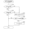
ここで、図5に示すように、書換処理用ソフトBによる書換モード処理では、まずS410にて、書換ツール7からの初期通信Bの信号を待ち、初期通信Bの信号を受信したならば(S410:YES)、S420に進んで、引き続き書換ツール7との初期通信Bを行う。 Here, as shown in FIG. 5, in the rewrite mode processing by the rewrite processing software B, first, in S410, if the initial communication B signal from the rewriting tool 7 is waited and the initial communication B signal is received ( (S410: YES), the process proceeds to S420, and the initial communication B with the rewriting tool 7 is continued.
そして、初期通信Bが終了すると、次のS430にて、書換ツール7からのデータ通信Bの信号(即ち、所定データ量毎の新制御ソフトB)を受信したか否かを判定し、そのデータ通信Bの信号を受信したならば、S440に進む。そして、S440では、データ通信Bの処理として、今回受信した所定データ量の新制御ソフトBをフラッシュメモリ23に更新して書き込む書換処理を行い、その後、S430に戻る。
When the initial communication B is completed, it is determined in next S430 whether or not the data communication B signal from the rewriting tool 7 (that is, the new control software B for each predetermined amount of data) has been received. If the communication B signal is received, the process proceeds to S440. In S440, as the process of data communication B, a rewrite process of updating and writing the new control software B having a predetermined data amount received this time to the
また、S430にて、データ通信Bの信号を受信していないと判定した場合には、S450に移行して、書換ツール7からの終了通知コマンドを受信したか否かを判定し、終了通知コマンドを受信してなければ、再びS430に戻る。 If it is determined in S430 that the data communication B signal has not been received, the process proceeds to S450, where it is determined whether an end notification command has been received from the rewriting tool 7, and an end notification command is determined. If not received, the process returns to S430 again.
一方、S450にて、終了通知コマンドを受信したと判定したならば、そのまま当該書換モード処理を終了し、図4のS390に進む。すると、マイコンBは、実質的な処理を行わない無限ループ状態になる。 On the other hand, if it is determined in S450 that the end notification command has been received, the rewrite mode process is terminated as it is, and the process proceeds to S390 in FIG. Then, the microcomputer B enters an infinite loop state where no substantial processing is performed.
次に図6は、マイコンAが実行する処理を表すフローチャートである。そして、図6において、S500の処理がフラッシュメモリ13内の制御ソフトAによって実現され、S510〜S575の処理がフラッシュメモリ13内の制御ソフトA以外のアプリケーションソフトAによって実現され、S580,S590の処理がROM11内の書換処理用ソフトAによって実現される。
Next, FIG. 6 is a flowchart showing processing executed by the microcomputer A. In FIG. 6, the process of S500 is realized by the control software A in the
図6に示すように、マイコンAは、初期状態から動作を開始すると、フラッシュメモリ13に格納されている制御ソフトAを実行することにより、通常の制御処理を行う(S500)。尚、前述したように、マイコンAは、この制御ソフトAによる制御処理により、マイコンBと内部通信線10を介して通信しながら他ECUへの電源供給制御や車載機器制御を行うと共に、WDT17を規定時間Ta以内毎にクリアし、更に、マイコンBの動作を監視するための図2の監視処理も行う。
As shown in FIG. 6, when the microcomputer A starts operating from the initial state, the microcomputer A performs normal control processing by executing the control software A stored in the flash memory 13 (S500). As described above, the microcomputer A performs control of power supply to other ECUs and control of in-vehicle devices while communicating with the microcomputer B via the
そして、マイコンAは、その制御処理を行っている最中に、書換ツール7からのセキュリティ通信Aの信号を受信したか否かを判定し(S510)、セキュリティ通信Aの信号を受信しなければ、制御処理を続ける(S510:NO→S500)。この状態が、通常モードの状態である。 Then, the microcomputer A determines whether or not the security communication A signal is received from the rewriting tool 7 during the control process (S510), and if the security communication A signal is not received. The control process is continued (S510: NO → S500). This state is a normal mode state.
一方、書換ツール7からのセキュリティ通信Aの信号を受信したならば(S510:YES)、S520に移行して、引き続き書換ツール7とのセキュリティ通信Aを行い、次のS530にて、セキュリティを解除して良いか否かを判定する。具体的には、書換ツール7とのセキュリティ通信Aが規定の手順で全て完了できたならば、セキュリティを解除して良いと判定する。 On the other hand, if the security communication A signal is received from the rewriting tool 7 (S510: YES), the process proceeds to S520, and the security communication A is continuously performed with the rewriting tool 7, and the security is released in the next S530. Judge whether or not to do so. Specifically, if the security communication A with the rewriting tool 7 has been completed in accordance with the specified procedure, it is determined that the security can be released.
そして、セキュリティを解除して良いと判定しなかった場合には、S500に戻って再び制御ソフトAによる制御処理を行うが、セキュリティを解除して良いと判定した場合には、S540に進む。 If it is not determined that the security can be released, the process returns to S500 and the control process by the control software A is performed again. If it is determined that the security can be released, the process proceeds to S540.
S540では、S530にてセキュリティを解除して良いと判定してから一定時間以内に書換ツール7からのモード切換コマンドAを受信したか否かを判定する。そして、一定時間内にモード切換コマンドAを受信しなければ、S500に戻って再び制御ソフトAによる制御処理を行うが、一定時間以内にモード切換コマンドAを受信したならば、S550に進んで、書換ツール7との書換モード移行通信Aを行う。 In S540, it is determined whether or not the mode switching command A from the rewriting tool 7 is received within a predetermined time after it is determined in S530 that the security can be canceled. If the mode switching command A is not received within a certain time, the process returns to S500 and the control process by the control software A is performed again. If the mode switching command A is received within the certain time, the process proceeds to S550. Rewrite mode transition communication A with the rewrite tool 7 is performed.
次にS560にて、書換モードに移行して良いか否かを判定する。具体的には、書換ツール7との書換モード移行通信Aが規定の手順で全て完了できたならば、書換モードに移行して良いと判定する。そして、書換モードに移行して良いと判定しなかった場合には、S500に戻って再び制御ソフトによる制御処理を行うが、書換モードに移行して良いと判定した場合には、S570に進む。 Next, in S560, it is determined whether or not the rewrite mode can be entered. Specifically, if the rewrite mode transition communication A with the rewrite tool 7 has been completed in accordance with a prescribed procedure, it is determined that the rewrite mode can be shifted. If it is not determined that the mode can be changed to the rewrite mode, the process returns to S500 and the control process by the control software is performed again. However, if it is determined that the mode can be changed to the rewrite mode, the process proceeds to S570.
S570では、フラッシュメモリ13へのデータ書き込みを許可した状態であることを示す書込許可判定信号Aを、アクティブレベル(本実施形態ではハイ)にし、その後、S575に進んで、図7の書換モード移行待ち処理を実行する。尚、マイコンAでは、S570の後、そのまま書換モードにはならずに書換モード移行待ち処理を実行する点が、マイコンBと異なっている。
In S570, the write permission determination signal A indicating that data writing to the
図7に示すように、書換モード移行待ち処理では、まずS610にて、WDT17をクリアし、次のS620にて、WDTクリアカウンタをリセットスタートさせる。尚、このWDTクリアカウンタは、WDT17をクリアする周期を計時するためのタイマカウンタであり、図示しない別のタイマ処理或いはハードウェアによって一定時間毎にカウントアップされる。 As shown in FIG. 7, in the rewrite mode transition waiting process, first, WDT 17 is cleared in S610, and the WDT clear counter is reset and started in next S620. The WDT clear counter is a timer counter for measuring the period for clearing the WDT 17, and is counted up at regular intervals by another timer process (not shown) or hardware.
そして、次にS630にて、書換ツール7からの書換対象切換コマンドを受信したか否かを判定し、書換対象切換コマンドを受信していないと判定したならば、S640に進む。 Next, in S630, it is determined whether or not a rewrite target switching command has been received from the rewriting tool 7. If it is determined that a rewrite target switching command has not been received, the process proceeds to S640.
S640では、オア回路31からの書込許可信号がアクティブレベル(ハイ)であるか否かを判定し、書込許可信号がアクティブレベルならば、次のS650にて、書換ツール7からの終了通知コマンドを受信したか否かを判定する。そして、終了通知コマンドを受信していなければ、次のS660にて、イグニッションスイッチ信号に基づき、操作部としてのイグニッションスイッチ(IGSW)がオンからオフに操作されたか否かを判定し、オフに操作されていなければ、S670に進む。
In S640, it is determined whether or not the write permission signal from the
S670では、WDTクリアカウンタの値が、WDT17のタイムオーバー時間である規定時間Taよりも短い一定時間(本実施形態では4ms)に相当する値に達しているか否かを判定し、4msに相当する値に達していなければ、S630に戻る。 In S670, it is determined whether or not the value of the WDT clear counter has reached a value corresponding to a certain time (4 ms in the present embodiment) shorter than the specified time Ta that is the time over time of the WDT 17, and a value corresponding to 4 ms. If not, the process returns to S630.
また、S670にて、WDTクリアカウンタの値が4msに相当する値に達していると判定した場合には、最初のS610に戻る。
また、S640にて書込許可信号がアクティブレベルでないと判定した場合、或いは、S650にて書換ツール7からの終了通知コマンドを受信したと判定した場合、或いは、S660にてイグニッションスイッチがオンからオフに操作されたと判定した場合には、S680に移行して、WDTクリアカウンタのカウントアップを停止させると共に、その状態でループする。
If it is determined in S670 that the value of the WDT clear counter has reached a value corresponding to 4 ms, the process returns to the first S610.
If it is determined in S640 that the write permission signal is not at the active level, if it is determined in S650 that an end notification command has been received from the rewriting tool 7, or if the ignition switch is turned off from S660. If it is determined that the WDT has been operated, the process proceeds to S680, where the count-up of the WDT clear counter is stopped and a loop is performed in that state.
すると、S610によるWDT17のクリアが実施されなくなるため、少なくとも規定
時間Taが経過すると、マイコンAは、WDT17によりリセットされて、制御ソフトAを実行する通常モードの状態へ復帰することとなる。
Then, since the WDT 17 is not cleared in S610, the microcomputer A is reset by the WDT 17 and returns to the normal mode in which the control software A is executed when at least the specified time Ta has elapsed.
一方、上記S630にて、書換ツール7からの書換対象切換コマンドを受信したと判定した場合には、当該書換モード移行待ち処理を終了し、プログラムの実行先を、ROM11内の書換処理用ソフトAへジャンプさせる。これにより、マイコンAの動作モードは、書換処理用ソフトAを実行する書換モードとなり、マイコンAは、その書換処理用ソフトAを実行することにより、書換モード処理(S580)を行う。
On the other hand, if it is determined in S630 that the rewrite object switching command has been received from the rewrite tool 7, the rewrite mode transition waiting process is terminated, and the program execution destination is changed to the rewrite process software A in the
つまり、マイコンAにおいて、図7の書換モード移行待ち処理を実行している状態は、制御ソフトAを実行せずに書換モードへ移行するのを待っている待機状態である。
そして、その待機状態において、書換ツール7からの書換対象切換コマンド及び終了通知コマンドを受信せず、オア回路31からの書込許可信号がアクティブレベルで且つイグニッションスイッチがオフに操作されなければ、S610及びS620の処理が4ms毎に実行され、その4ms毎にWDT17をクリアすることとなる。これは、WDT17によってリセットされないようにするためである。尚、マイコンAが正規の手順でこの待機状態となった場合には、少なくとも図6におけるS570の処理により、オア回路31からの書込許可信号は必ずアクティブレベルになっている。
That is, in the microcomputer A, the state in which the rewrite mode transition waiting process in FIG. 7 is executed is a standby state in which the control software A is not executed and the transition to the rewrite mode is waited.
In the standby state, if the rewrite target switching command and the end notification command from the rewriting tool 7 are not received, the write permission signal from the
また、待機状態になっても、オア回路31からの書込許可信号が非アクティブレベルであった場合(S640:NO)、或いは、待機状態である間に、書換ツール7からの終了通知コマンドを受信するか(S650:YES)、イグニッションスイッチがオフに操作されたならば(S660:YES)、マイコンAはWDT17によりリセットされて通常モードに復帰することとなる。
Even if the write permission signal from the
一方、待機状態である場合に、書換ツール7からの書換対象切換コマンドを受信したならば(S630:YES)、待機状態から抜けて、書換処理用ソフトAを実行する書換モードへ移行することとなる。 On the other hand, if the rewriting object switching command is received from the rewriting tool 7 in the standby state (S630: YES), the process leaves the standby state and shifts to the rewriting mode in which the rewriting processing software A is executed. Become.
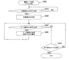
そして、図8に示すように、書換処理用ソフトAによる書換モード処理(即ち、書換モードの場合に行う処理)では、まずS705にて、時間カウンタをリセットスタートさせる。尚、この時間カウンタはタイムアウト機能用のタイマカウンタであり、図示しない別のタイマ処理或いはハードウェアによって一定時間毎にカウントアップされる。 As shown in FIG. 8, in the rewrite mode process (that is, the process performed in the rewrite mode) by the rewrite process software A, first, in S705, the time counter is reset and started. This time counter is a timer counter for a time-out function, and is counted up at regular intervals by another timer process (not shown) or hardware.
次にS710にて、書換ツール7からの初期通信Aの信号を受信したか否かを判定し、その信号を受信していなければ、S715に進む。そして、S715では、時間カウンタの値がタイムアウト時間(本実施形態では5秒)に相当する値を超えた否かを判定し、5秒を超えていなければ、S710に戻る。 Next, in S710, it is determined whether or not the signal of the initial communication A from the rewriting tool 7 has been received. If the signal has not been received, the process proceeds to S715. In S715, it is determined whether or not the value of the time counter has exceeded a value corresponding to the timeout time (5 seconds in the present embodiment). If it has not exceeded 5 seconds, the process returns to S710.
また、S710にて、初期通信Aの信号を受信したと判定した場合には、S720に進んで、引き続き書換ツール7との初期通信Aを行う。そして、初期通信Aが終了すると、次のS725にて、再び時間カウンタをリセットスタートさせる。 If it is determined in S710 that the signal of the initial communication A has been received, the process proceeds to S720, and the initial communication A with the rewriting tool 7 is continued. When the initial communication A is completed, the time counter is reset and started again in the next S725.
次にS730にて、書換ツール7からのデータ通信Aの信号(即ち、所定データ量毎の新制御ソフトA)を受信したか否かを判定する。そして、データ通信Aの信号を受信したならば、S740に進み、データ通信Aの処理として、今回受信した所定データ量の新制御ソフトAをフラッシュメモリ13に更新して書き込む書換処理を行い、次のS745にて、再び時間カウンタをリセットスタートさせた後、S730に戻る。
Next, in S730, it is determined whether or not a signal of data communication A from the rewriting tool 7 (that is, new control software A for each predetermined data amount) has been received. If the signal of the data communication A is received, the process proceeds to S740, and as the processing of the data communication A, a rewriting process is performed in which the new control software A having a predetermined data amount received this time is updated and written to the
また、S730にて、データ通信Aの信号を受信していないと判定した場合には、S750に移行して、書換ツール7からの終了通知コマンドを受信したか否かを判定し、終了通知コマンドを受信してなければ、S755に進む。そして、S755では、時間カウンタの値がタイムアウト時間の5秒に相当する値を超えた否かを判定し、5秒を超えていなければ、S730に戻る。 If it is determined in S730 that the data communication A signal has not been received, the process proceeds to S750, where it is determined whether an end notification command from the rewriting tool 7 has been received, and the end notification command is determined. If not received, the process proceeds to S755. In S755, it is determined whether or not the value of the time counter exceeds the value corresponding to the timeout time of 5 seconds. If it does not exceed 5 seconds, the process returns to S730.
また、S750にて、書換ツール7からの終了通知コマンドを受信したと判定したならば、ECU1における制御ソフトの書き換えが全て完了したということであるため、そのまま当該書換モード処理を終了して、図6のS590に進む。そして、そのS590にて、プログラムの実行先を制御ソフトAの先頭へジャンプさせる。すると、マイコンAは通常モードに戻ることとなる。 If it is determined in S750 that the end notification command from the rewriting tool 7 has been received, it means that the rewriting of the control software in the ECU 1 has been completed. Proceed to S590 of 6. In step S590, the program execution destination is jumped to the top of the control software A. Then, the microcomputer A returns to the normal mode.
一方、上記S715とS755との何れかにおいて、時間カウンタの値が5秒に相当する値を超えたと判定した場合には、S760に移行して、この場合にもプログラムの実行先を制御ソフトAの先頭へジャンプさせる。よって、この場合、マイコンAは、制御ソフトAの書き換えが完了していなくても通常モードに戻ることとなる。 On the other hand, if it is determined in any one of S715 and S755 that the value of the time counter has exceeded a value corresponding to 5 seconds, the process proceeds to S760, and in this case as well, the execution destination of the program is set to the control software A. Jump to the top of Therefore, in this case, the microcomputer A returns to the normal mode even if the rewriting of the control software A is not completed.
つまり、電源電圧Vbで動作するマイコンBならば、誤って書換モードに移行したとしても、イグニッションスイッチをオフ→オンすれば、強制的に通常モードへと復帰させることができるが、常時供給される電源電圧Vaで動作するマイコンAには、誤って書換モードに移行した場合のフェイルセーフ機能として、図8のS705,S715,S725,S745,S755,S760によるタイムアウト機能が備えられている。具体的には、書換モードになっても、制御ソフトAの書換処理を実施するのに必要な初期通信Aの信号及びデータ通信Aの信号と終了通知コマンドとの何れかが、書換ツール7から5秒以内に送信されてこなければ(何も受信しない状態が5秒を超えたら)、通常モードに復帰するようになっている。 In other words, if the microcomputer B operates with the power supply voltage Vb, it can be forcibly returned to the normal mode by turning the ignition switch from OFF to ON even if the microcomputer B erroneously shifts to the rewrite mode. The microcomputer A operating with the power supply voltage Va is provided with a time-out function according to S705, S715, S725, S745, S755, and S760 of FIG. 8 as a fail-safe function when the mode is erroneously shifted to the rewrite mode. Specifically, even in the rewrite mode, any one of the initial communication A signal and the data communication A signal and the end notification command necessary for executing the rewrite process of the control software A is received from the rewrite tool 7. If it is not transmitted within 5 seconds (if nothing is received for more than 5 seconds), it returns to the normal mode.
尚、図示は省略しているが、マイコンAは、書換モードの場合にも、WDT17によってリセットされないようにするために、WDT17を規定時間Ta以内毎(例えば4ms毎)にクリアする処理を行っている。 Although not shown, the microcomputer A performs a process of clearing the WDT 17 within a predetermined time Ta (for example, every 4 ms) so that the WDT 17 is not reset even in the rewrite mode. Yes.
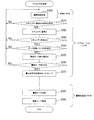
以上のようなECU1において、マイコンA,Bの制御ソフトを書き換える場合には、図9に示すように、書換ツール7が各マイコンA,Bとセキュリティ通信A,Bを行って、そのマイコンA,Bにおけるセキュリティを解除させる。 In the ECU 1 as described above, when the control software of the microcomputers A and B is rewritten, as shown in FIG. 9, the rewriting tool 7 performs security communication A and B with the microcomputers A and B, and the microcomputers A and B Release security in B.
そして、書換ツール7は、その後、各マイコンA,Bへモード切換コマンドA,Bを送信して、各マイコンA,Bと書換モード移行通信A,Bを行う。
すると、制御ソフトを先に書き換える方のマイコンBは、通常モードから書換モードに移行し、また、制御ソフトを後で書き換える方のマイコンAは、通常モードから抜けて、図7の書換モード移行待ち処理を行う待機状態となる。
Then, the rewriting tool 7 transmits mode switching commands A and B to the microcomputers A and B, and performs rewrite mode transition communication A and B with the microcomputers A and B.
Then, the microcomputer B that rewrites the control software first shifts from the normal mode to the rewrite mode, and the microcomputer A that rewrites the control software later leaves the normal mode and waits for the rewrite mode shift of FIG. It will be in the standby state which performs processing.
その後、書換ツール7と書換モードのマイコンBが初期通信B及びデータ通信Bを行うことにより、書換ツール7からマイコンBへ、書き換えるべき新制御ソフトBが送信され、マイコンBは、フラッシュメモリ23内の制御ソフトBを、その書換ツール7からの新制御ソフトBに書き換えることとなる。 After that, the rewriting tool 7 and the microcomputer B in the rewriting mode perform the initial communication B and the data communication B, so that the new control software B to be rewritten is transmitted from the rewriting tool 7 to the microcomputer B. The control software B is rewritten with the new control software B from the rewriting tool 7.
そして、マイコンBの制御ソフトBの書き換えが終了すると、書換ツール7は、マイコンAへ、書換対象切換コマンド(モード移行許可指令に相当)を送信する。すると、マイコンAは、この時点で書換モードに移行する。 When the rewriting of the control software B of the microcomputer B is completed, the rewriting tool 7 transmits a rewriting target switching command (corresponding to a mode transition permission command) to the microcomputer A. Then, the microcomputer A shifts to the rewrite mode at this point.
その後、書換ツール7と書換モードのマイコンAが初期通信A及びデータ通信Aを行うことにより、書換ツール7からマイコンAへ、書き換えるべき新制御ソフトAが送信され、マイコンAは、フラッシュメモリ13内の制御ソフトAを、その書換ツール7からの新制御ソフトAに書き換えることとなる。 After that, the rewriting tool 7 and the microcomputer A in the rewriting mode perform the initial communication A and the data communication A, whereby the new control software A to be rewritten is transmitted from the rewriting tool 7 to the microcomputer A. The control software A is rewritten with the new control software A from the rewriting tool 7.
そして、マイコンAの制御ソフトAの書き換えが終了すると、書換ツール7は、マイコンA,Bの両方へ終了通知コマンドを送信する。
すると、マイコンAは、図8の書換モード処理を終了して通常モードに復帰し、新制御ソフトAの実行を開始する。また、マイコンBは、図5の書換モード処理を終了するが、制御ソフトBは実行せずに無限ループ状態(無制御状態)となる。
When the rewriting of the control software A of the microcomputer A is completed, the rewriting tool 7 transmits an end notification command to both the microcomputers A and B.
Then, the microcomputer A ends the rewrite mode process of FIG. 8 and returns to the normal mode, and starts executing the new control software A. Further, the microcomputer B ends the rewrite mode process of FIG. 5, but the control software B is not executed and enters an infinite loop state (no control state).
このため、マイコンBは、通常モードに戻ったマイコンAが図2の監視処理を実行することで実現される監視機能によってリセットされる。そして、マイコンBは、そのマイコンAによるリセットで通常モードに復帰して、新制御ソフトBの実行を開始し、この時点から、両方のマイコンA,Bが本来の制御機能を果たすこととなる。 Therefore, the microcomputer B is reset by the monitoring function realized by the microcomputer A that has returned to the normal mode executing the monitoring process of FIG. Then, the microcomputer B returns to the normal mode by the reset by the microcomputer A and starts the execution of the new control software B. From this point of time, both the microcomputers A and B perform the original control function.
尚、本実施形態において、書換ツール7は終了通知コマンドをマイコンA,Bの両方に送信するようになっているが、終了通知コマンドをマイコンAだけに送信するようにしても全く同じである。つまり、マイコンBが書換モード時に実行する図5の書換モード処理では、制御ソフトBの書き換えが終了してから終了通知コマンドを受信しなければ、「S430:NO→S450:NO→S430」の無限ループ状態となり、やはり、マイコンBは、通常モードに戻ったマイコンAの監視機能によりリセットされて通常モードに復帰することとなるからである。 In the present embodiment, the rewriting tool 7 transmits the end notification command to both the microcomputers A and B. However, the same is true if the end notification command is transmitted only to the microcomputer A. That is, in the rewrite mode process of FIG. 5 executed by the microcomputer B in the rewrite mode, if the end notification command is not received after the rewrite of the control software B is completed, “S430: NO → S450: NO → S430” infinite. This is because the microcomputer B is reset and returned to the normal mode by the monitoring function of the microcomputer A that has returned to the normal mode.
ここで、本実施形態のECU1においては、マイコンA,Bの両方を通常モードから離脱させているため、マイコンBの制御ソフトBの書き換えを行っている最中に、マイコンAが通常モード時の監視機能(即ち、図2の監視処理による機能)によってマイコンBをリセットしないようにすることができる。 Here, in the ECU 1 of the present embodiment, since both the microcomputers A and B are separated from the normal mode, the microcomputer A is in the normal mode while the control software B of the microcomputer B is being rewritten. The microcomputer B can be prevented from being reset by the monitoring function (that is, the function by the monitoring process of FIG. 2).
そして更に、マイコンBの制御ソフトBの書き換えを行っている最中に、マイコンAは、通常モードから離脱するが書換モードにも移行せずに、図7の書換モード移行待ち処理を実行する待機状態となるため、書換モード時のタイムアウト機能(図8のS705,S715,S725,S745,S755,S760による機能)によって通常モードに復帰してしまうことはない。このため、マイコンBに続いて、マイコンAの制御ソフトAも確実に書き換えることができる。 Further, while the control software B of the microcomputer B is being rewritten, the microcomputer A leaves the normal mode but does not enter the rewrite mode, and waits for executing the rewrite mode transition waiting process of FIG. Therefore, the normal mode is not restored by the time-out function in the rewrite mode (functions in S705, S715, S725, S745, S755, and S760 in FIG. 8). For this reason, the control software A of the microcomputer A can be surely rewritten following the microcomputer B.
よって、マイコンAが通常モード時にマイコンBを監視することと、マイコンBの制御ソフトBとマイコンAの制御ソフトAをその順に連続して書き換え可能にすることとを両立させることができる。 Therefore, the microcomputer A can monitor the microcomputer B in the normal mode and can simultaneously rewrite the control software B of the microcomputer B and the control software A of the microcomputer A in that order.
また、本実施形態のECU1において、マイコンBは、制御ソフトBの書き換えが終了すると無限ループ状態となり、マイコンAは、制御ソフトAの書き換えが終了すると通常モードに復帰して、その通常モード時の監視機能によりマイコンBをリセットして通常モードに復帰させるようになっている。このため、2つのマイコンA,Bを自動的に且つほぼ同時に通常モードへと復帰させることができ、2つのマイコンA,Bによる制御開始の同期化が容易となる。 Further, in the ECU 1 of the present embodiment, the microcomputer B enters an infinite loop state when the rewriting of the control software B is completed, and the microcomputer A returns to the normal mode when the rewriting of the control software A is completed, and the microcomputer B is in the normal mode. The microcomputer B is reset by the monitoring function to return to the normal mode. For this reason, the two microcomputers A and B can be automatically and almost simultaneously returned to the normal mode, and the control start by the two microcomputers A and B can be easily synchronized.
また、本実施形態において、マイコンAは、書換ツール7からの書換対象切換コマンド
を受けると、待機状態から書換モードへ移行するようになっているため、書換ツール7から送信されるコマンド(指令)として、マイコンAを待機状態から書換モードに移行されるための特別なコマンドを新たに設ける必要がない。
Further, in the present embodiment, when the microcomputer A receives the rewrite target switching command from the rewriting tool 7, the microcomputer A shifts from the standby state to the rewriting mode. Therefore, the command (command) transmitted from the rewriting tool 7. As a result, there is no need to newly provide a special command for shifting the microcomputer A from the standby state to the rewrite mode.
また、本実施形態において、マイコンAは、待機状態となっている場合に、書換ツール7からの終了通知コマンドを受けると(S650:YES)、通常モードに復帰するようになっている。 In this embodiment, when the microcomputer A is in a standby state and receives an end notification command from the rewriting tool 7 (S650: YES), the microcomputer A returns to the normal mode.
このため、マイコンBの制御ソフトBだけを書き換える場合にも対応することができる。つまり、制御ソフトBだけを書き換える場合、書換ツール7は、図3(図9)におけるS260〜S280の処理を実行せずに、制御ソフトBの書き換え(データ通信B)が終了したら、終了通知コマンドを送信する。すると、マイコンAは、待機モードから通常モードに戻り、制御ソフトBの書き換えが終わって無限ループ状態になっているマイコンBをリセットし通常モードに復帰させることとなる。 For this reason, it is possible to cope with the case where only the control software B of the microcomputer B is rewritten. That is, when only the control software B is rewritten, the rewriting tool 7 does not execute the processes of S260 to S280 in FIG. 3 (FIG. 9), and ends the rewriting of the control software B (data communication B). Send. Then, the microcomputer A returns from the standby mode to the normal mode, resets the microcomputer B in the infinite loop state after rewriting of the control software B, and returns to the normal mode.
尚、制御ソフトBだけを書き換える場合に、書換ツール7が図3(図9)におけるS220の処理も実行せずに、マイコンAへモード切換コマンドAを送信しない構成も考えられる。その場合には、例えば、マイコンBが、書換ツール7からのモード切換コマンドBを受信した時点で、内部通信線10を介しマイコンAと通信して、マイコンAを書換モード移行待ち処理を実行する待機状態に移行させるように構成することができる。
Note that when only the control software B is rewritten, a configuration in which the rewriting tool 7 does not transmit the mode switching command A to the microcomputer A without executing the processing of S220 in FIG. 3 (FIG. 9) is also conceivable. In that case, for example, when the microcomputer B receives the mode switching command B from the rewriting tool 7, it communicates with the microcomputer A via the
また、本実施形態において、マイコンAは、待機状態となっている場合に、イグニッションスイッチがオンからオフに操作されても(S660:YES)、通常モードに復帰するようになっている。 In the present embodiment, when the microcomputer A is in a standby state, the microcomputer A returns to the normal mode even if the ignition switch is operated from on to off (S660: YES).
このため、マイコンBの制御ソフトBだけを書き換える場合に、仮に書換ツール7がマイコンAへ終了通知コマンドを送信しなくても、マイコンA,Bを通常モードに復帰させることができる。また、マイコンAが何らかの原因で誤って待機状態になってしまっても、イグニッションスイッチをオフに操作することにより、マイコンAを強制的に通常モードへと復帰させることができる。 Therefore, when only the control software B of the microcomputer B is rewritten, the microcomputers A and B can be returned to the normal mode even if the rewriting tool 7 does not transmit an end notification command to the microcomputer A. Even if the microcomputer A is accidentally put into a standby state for some reason, the microcomputer A can be forcibly returned to the normal mode by turning off the ignition switch.
また、本実施形態において、マイコンAは、待機状態となっている場合に、オア回路31からの書込許可信号がアクティブレベルでなければ(S640:NO)、通常モードに復帰するようになっている。
In the present embodiment, when the microcomputer A is in a standby state, if the write permission signal from the
このため、マイコンAが何らかの原因で誤って待機状態になってしまっても、そのような場合には、マイコンAを自動的に通常モードへと復帰させることができる。前述したように、マイコンAが正規の手順で待機状態となった場合には、マイコンA側の図6におけるS570の処理、或いはマイコンB側の図4におけるS370の処理により、オア回路31からの書込許可信号は必ずアクティブレベルになっているはずであり、マイコンAが待機状態になった場合に、その書込許可信号が非アクティブレベルであれば、誤って待機状態になったと考えられるからである。
For this reason, even if the microcomputer A accidentally enters a standby state for some reason, in such a case, the microcomputer A can be automatically returned to the normal mode. As described above, when the microcomputer A enters the standby state according to a normal procedure, the process from the
尚、上記実施形態では、マイコンAが第1マイコンに相当し、マイコンBが第2マイコンに相当している。
以上、本発明の一実施形態について説明したが、本発明はこうした実施形態に何等限定されるものではなく、本発明の要旨を逸脱しない範囲において、種々なる態様で実施し得ることは勿論である。
In the above embodiment, the microcomputer A corresponds to the first microcomputer, and the microcomputer B corresponds to the second microcomputer.
As mentioned above, although one Embodiment of this invention was described, this invention is not limited to such Embodiment at all, Of course, in the range which does not deviate from the summary of this invention, it can implement in a various aspect. .
例えば、上記実施形態では、書き換える対象が制御ソフトA,Bだけであったが、フラッシュメモリ13,23内のアプリケーションソフトA,B全体を書き換えるようにしても良い。この場合、アプリケーションソフトA,Bのうち、制御ソフトA,B以外の部分は、同じ内容に書き換えれば良い。
For example, in the above embodiment, only the control software A and B are rewritten, but the entire application software A and B in the
また、図7のS660では、イグニッションスイッチ以外の他のスイッチ(例えばエンジンを始動させるためのスタートスイッチ)が操作されたか否かを判定するように構成しても良い。 In S660 of FIG. 7, it may be configured to determine whether or not a switch other than the ignition switch (for example, a start switch for starting the engine) is operated.
また、マイコンBもマイコンAと同様に、常時供給の電源電圧Vaを受けて動作する構成であっても良い。また、マイコンは3つ以上あっても良い。 Similarly to the microcomputer A, the microcomputer B may be configured to operate by receiving the constantly supplied power supply voltage Va. Further, there may be three or more microcomputers.
1…ECU(電子制御装置)、A,B…マイコン、2…車両内通信線、3,5…通信ドライバ、7…書換ツール(外部装置)、9…コネクタ、10…内部通信線、11,21…ROM、13,23…フラッシュメモリ(書換可能不揮発性メモリ)、15,25…コア、17…WDT(ウォッチドッグタイマ)、31…オア回路 DESCRIPTION OF SYMBOLS 1 ... ECU (electronic control apparatus), A, B ... Microcomputer, 2 ... In-vehicle communication line, 3, 5 ... Communication driver, 7 ... Rewriting tool (external device), 9 ... Connector, 10 ... Internal communication line, 11, 21 ... ROM, 13, 23 ... Flash memory (rewritable nonvolatile memory), 15, 25 ... Core, 17 ... WDT (watchdog timer), 31 ... OR circuit
Claims (8)
前記第1マイコン及び第2マイコンの各々は、電気的にデータの書き換えが可能な不揮発性メモリを有すると共に、通常モード時には、その不揮発性メモリに格納された制御ソフトウェアを実行することで制御対象を制御し、前記外部装置からのモード切換指令を受けた場合には、前記制御ソフトウェアとは別の書換処理用ソフトウェアを実行する書換モードに移行して、その書換処理用ソフトウェアを実行することにより、前記不揮発性メモリ内の制御ソフトウェアを前記外部装置から送信されて来る制御ソフトウェアに書き替えるための書換処理を行うようになっており、
また、前記2つのマイコンの制御ソフトウェアが連続して書き換えられる場合には、前記外部装置から前記各マイコンへ前記モード切換指令が送信されると共に、前記第2マイコンの方が先に制御ソフトウェアの書き換えが実施されるようになっており、
更に、前記2つのマイコンのうち、少なくとも前記第1マイコンは、常時電源が供給されるようになっていると共に、
前記第1マイコンが実行する前記書換処理用ソフトウェアには、当該第1マイコンにおいて前記書換処理を実施するために必要な所定の情報が前記外部装置から当該第1マイコンへ一定時間以内に送られてきたか否かを監視し該情報が送られてこなければ前記制御ソフトウェアを実行する通常モードに復帰するタイムアウト機能を、当該第1マイコンに実現させるプログラムが含まれている電子制御装置において、
前記第1マイコンは、前記モード切換指令を受けた場合に、そのまま前記書換モードに移行するのではなく、前記制御ソフトウェアを実行せずに前記書換モードへ移行するのを待つ待機状態となり、その後、前記外部装置からのモード移行許可指令を受けると、前記書換モードに移行するようになっていること、
を特徴とする電子制御装置。 A first microcomputer and a second microcomputer that are communicably connected to an external device;
Each of the first microcomputer and the second microcomputer has a non-volatile memory capable of electrically rewriting data and, in the normal mode, executes control software stored in the non-volatile memory to control objects. Control, when receiving a mode switching command from the external device, by shifting to a rewrite mode for executing rewrite processing software different from the control software, by executing the rewrite processing software, A rewriting process for rewriting the control software in the non-volatile memory with the control software transmitted from the external device is performed,
When the control software of the two microcomputers is continuously rewritten, the mode switching command is transmitted from the external device to each microcomputer, and the second microcomputer first rewrites the control software. Has been implemented,
Furthermore, among the two microcomputers, at least the first microcomputer is constantly supplied with power,
The rewriting processing software executed by the first microcomputer receives predetermined information necessary for performing the rewriting processing in the first microcomputer from the external device to the first microcomputer within a predetermined time. In an electronic control device including a program that causes the first microcomputer to implement a time-out function for returning to a normal mode in which the control software is executed if the information is not sent.
When the first microcomputer receives the mode switching command, it does not shift to the rewrite mode as it is, but waits to shift to the rewrite mode without executing the control software. Upon receipt of the mode transition permission command from the external device, the mode is shifted to the rewrite mode.
An electronic control device.
前記第1マイコンが実行する前記制御ソフトウェアには、前記第2マイコンにて該第2マイコンの前記不揮発性メモリに格納されている制御ソフトウェアが正常に実行されているか否かを監視すると共に、その制御ソフトウェアが正常に実行されていないと判断すると前記第2マイコンをリセットするための動作を行う監視機能を、前記第1マイコンに実現させるプログラムが含まれていること、
を特徴とする電子制御装置。 The electronic control device according to claim 1.
The control software executed by the first microcomputer monitors whether or not the control software stored in the non-volatile memory of the second microcomputer is normally executed by the second microcomputer, and A program that causes the first microcomputer to include a monitoring function for performing an operation for resetting the second microcomputer when it is determined that the control software is not normally executed;
An electronic control device.
前記第1マイコンは、前記書換処理が終了すると通常モードに復帰するようになっており、
前記第2マイコンは、前記書換処理が終了すると、前記制御ソフトウェアを実行しない無制御状態となり、その後、前記第1マイコンの前記監視機能によりリセットされることで通常モードに復帰すること、
を特徴とする電子制御装置。 The electronic control device according to claim 2,
The first microcomputer is configured to return to the normal mode when the rewriting process is completed,
When the rewriting process is completed, the second microcomputer enters a non-control state in which the control software is not executed, and then is returned to the normal mode by being reset by the monitoring function of the first microcomputer.
An electronic control device.
前記モード移行許可指令は、前記外部装置が制御ソフトウェアの書換対象を前記第1マイコン以外のマイコンから前記第1マイコンに切り換える場合に送信する書換対象切換指令であること、
を特徴とする電子制御装置。 The electronic control device according to any one of claims 1 to 3,
The mode transition permission command is a rewrite target switching command that is transmitted when the external device switches a rewrite target of control software from a microcomputer other than the first microcomputer to the first microcomputer.
An electronic control device.
前記第1マイコンは、前記待機状態となっている場合に、特定の復帰条件が成立したか
否かを判定し、その復帰条件が成立したと判定すると、通常モードに復帰するようになっていること、
を特徴とする電子制御装置。 The electronic control device according to any one of claims 1 to 4,
When the first microcomputer is in the standby state, the first microcomputer determines whether or not a specific return condition is satisfied, and when it is determined that the return condition is satisfied, the first microcomputer returns to the normal mode. thing,
An electronic control device.
前記第1マイコンは、前記待機状態となっている場合に、前記外部装置から、制御ソフトウェアの書き換えが終了したことを示す終了通知が送信されてきたか否かを判定し、その終了通知が送信されてきたならば、前記復帰条件が成立したとして通常モードに復帰すること、
を特徴とする電子制御装置。 The electronic control device according to claim 5.
When the first microcomputer is in the standby state, the first microcomputer determines whether or not an end notification indicating that the rewriting of the control software has ended is transmitted from the external device, and the end notification is transmitted. If the return condition is satisfied, return to the normal mode,
An electronic control device.
前記第1マイコンは、前記待機状態となっている場合に、特定の操作部が操作されたか否かを判定し、その操作部が操作されたならば、前記復帰条件が成立したとして通常モードに復帰するようになっていること、
を特徴とする電子制御装置。 The electronic control device according to claim 5 or 6,
When the first microcomputer is in the standby state, the first microcomputer determines whether or not a specific operation unit has been operated. If the operation unit has been operated, the return condition is established and the normal mode is set. To come back,
An electronic control device.
前記第1マイコンは、前記待機状態となっている場合に、当該第1マイコンが該待機状態であるならばアクティブレベルとなるはずの信号をモニタし、その信号がアクティブレベルでなければ通常モードに復帰するようになっていること、
を特徴とする電子制御装置。 The electronic control device according to any one of claims 1 to 7,
When the first microcomputer is in the standby state, the first microcomputer monitors a signal that should be at an active level if the first microcomputer is in the standby state. To come back,
An electronic control device.
Priority Applications (3)
| Application Number | Priority Date | Filing Date | Title |
|---|---|---|---|
| JP2007085046A JP4367513B2 (en) | 2007-03-28 | 2007-03-28 | Electronic control unit |
| US12/056,058 US7831678B2 (en) | 2007-03-28 | 2008-03-26 | Electronic control apparatus |
| EP08005786.2A EP1975788B1 (en) | 2007-03-28 | 2008-03-27 | Electronic control apparatus |
Applications Claiming Priority (1)
| Application Number | Priority Date | Filing Date | Title |
|---|---|---|---|
| JP2007085046A JP4367513B2 (en) | 2007-03-28 | 2007-03-28 | Electronic control unit |
Publications (2)
| Publication Number | Publication Date |
|---|---|
| JP2008242995A true JP2008242995A (en) | 2008-10-09 |
| JP4367513B2 JP4367513B2 (en) | 2009-11-18 |
Family
ID=39484566
Family Applications (1)
| Application Number | Title | Priority Date | Filing Date |
|---|---|---|---|
| JP2007085046A Expired - Fee Related JP4367513B2 (en) | 2007-03-28 | 2007-03-28 | Electronic control unit |
Country Status (3)
| Country | Link |
|---|---|
| US (1) | US7831678B2 (en) |
| EP (1) | EP1975788B1 (en) |
| JP (1) | JP4367513B2 (en) |
Cited By (9)
| Publication number | Priority date | Publication date | Assignee | Title |
|---|---|---|---|---|
| WO2012001482A1 (en) | 2010-06-28 | 2012-01-05 | Toyota Jidosha Kabushiki Kaisha | Electronic control unit and control method thereof |
| WO2013021423A1 (en) * | 2011-08-10 | 2013-02-14 | トヨタ自動車株式会社 | Reprogramming system and reprogramming method |
| JP2014099099A (en) * | 2012-11-15 | 2014-05-29 | Denso Corp | Control system |
| JP2014164596A (en) * | 2013-02-26 | 2014-09-08 | Denso Corp | Control system |
| WO2015076012A1 (en) * | 2013-11-20 | 2015-05-28 | トヨタ自動車株式会社 | Electronic control device and software rewriting system |
| JP2015102964A (en) * | 2013-11-22 | 2015-06-04 | 株式会社デンソー | Electronic control unit |
| JP2020138590A (en) * | 2019-02-27 | 2020-09-03 | 株式会社デンソーテン | Control device, control device system, and control method of control device |
| JP2021149605A (en) * | 2020-03-19 | 2021-09-27 | 株式会社デンソーテン | Electronic control device and program re-write control method |
| JP2023151414A (en) * | 2022-03-31 | 2023-10-16 | 本田技研工業株式会社 | Vehicle control system, program writing method, and vehicle manufacturing method |
Families Citing this family (4)
| Publication number | Priority date | Publication date | Assignee | Title |
|---|---|---|---|---|
| JP5702829B2 (en) * | 2013-05-23 | 2015-04-15 | 本田技研工業株式会社 | Relay device |
| US9466159B1 (en) * | 2015-04-10 | 2016-10-11 | J. J. Keller & Associates, Inc. | Methods and systems for automatically identifying a data source for an on-board recorder |
| JP6524989B2 (en) * | 2016-11-15 | 2019-06-05 | トヨタ自動車株式会社 | Operation guarantee method of arithmetic unit |
| KR20230140166A (en) * | 2022-03-29 | 2023-10-06 | 에스케이하이닉스 주식회사 | Storage device and operating method thereof |
Citations (3)
| Publication number | Priority date | Publication date | Assignee | Title |
|---|---|---|---|---|
| JPH10177504A (en) * | 1996-12-18 | 1998-06-30 | Denso Corp | Electronic control unit |
| JP2000235487A (en) * | 1999-02-17 | 2000-08-29 | Denso Corp | Electronic control unit |
| JP2003196256A (en) * | 2001-12-26 | 2003-07-11 | Denso Corp | Electronic control unit |
Family Cites Families (8)
| Publication number | Priority date | Publication date | Assignee | Title |
|---|---|---|---|---|
| JP3881069B2 (en) | 1996-10-08 | 2007-02-14 | 株式会社デンソー | Electronic equipment |
| US6275911B1 (en) | 1996-09-20 | 2001-08-14 | Denso Corporation | Memory writing device for an electronic device |
| US6144887A (en) | 1996-12-09 | 2000-11-07 | Denso Corporation | Electronic control unit with reset blocking during loading |
| JP3137012B2 (en) | 1996-12-09 | 2001-02-19 | 株式会社デンソー | Electronic control unit |
| JP3828335B2 (en) | 2000-04-13 | 2006-10-04 | 本田技研工業株式会社 | Rewriting system for vehicle control device |
| EP1376344A3 (en) | 2002-06-17 | 2005-08-24 | Seiko Epson Corporation | Apparatus and method of rewriting firmware |
| KR20060054980A (en) | 2004-11-17 | 2006-05-23 | 삼성전자주식회사 | Software upgrade method of a device having a plurality of microprocessors and device therefor |
| JP2007085046A (en) | 2005-09-21 | 2007-04-05 | Sekisui House Ltd | Snow roof tiles |
-
2007
- 2007-03-28 JP JP2007085046A patent/JP4367513B2/en not_active Expired - Fee Related
-
2008
- 2008-03-26 US US12/056,058 patent/US7831678B2/en not_active Expired - Fee Related
- 2008-03-27 EP EP08005786.2A patent/EP1975788B1/en not_active Ceased
Patent Citations (3)
| Publication number | Priority date | Publication date | Assignee | Title |
|---|---|---|---|---|
| JPH10177504A (en) * | 1996-12-18 | 1998-06-30 | Denso Corp | Electronic control unit |
| JP2000235487A (en) * | 1999-02-17 | 2000-08-29 | Denso Corp | Electronic control unit |
| JP2003196256A (en) * | 2001-12-26 | 2003-07-11 | Denso Corp | Electronic control unit |
Cited By (12)
| Publication number | Priority date | Publication date | Assignee | Title |
|---|---|---|---|---|
| WO2012001482A1 (en) | 2010-06-28 | 2012-01-05 | Toyota Jidosha Kabushiki Kaisha | Electronic control unit and control method thereof |
| CN102971685A (en) * | 2010-06-28 | 2013-03-13 | 丰田自动车株式会社 | Electronic control unit and control method thereof |
| WO2013021423A1 (en) * | 2011-08-10 | 2013-02-14 | トヨタ自動車株式会社 | Reprogramming system and reprogramming method |
| JP2014099099A (en) * | 2012-11-15 | 2014-05-29 | Denso Corp | Control system |
| JP2014164596A (en) * | 2013-02-26 | 2014-09-08 | Denso Corp | Control system |
| WO2015076012A1 (en) * | 2013-11-20 | 2015-05-28 | トヨタ自動車株式会社 | Electronic control device and software rewriting system |
| JP2015102964A (en) * | 2013-11-22 | 2015-06-04 | 株式会社デンソー | Electronic control unit |
| JP2020138590A (en) * | 2019-02-27 | 2020-09-03 | 株式会社デンソーテン | Control device, control device system, and control method of control device |
| JP7244299B2 (en) | 2019-02-27 | 2023-03-22 | 株式会社デンソーテン | CONTROLLER, CONTROLLER SYSTEM AND METHOD OF CONTROLLING CONTROLLER |
| JP2021149605A (en) * | 2020-03-19 | 2021-09-27 | 株式会社デンソーテン | Electronic control device and program re-write control method |
| JP7411467B2 (en) | 2020-03-19 | 2024-01-11 | 株式会社デンソーテン | Electronic control device and program rewriting control method |
| JP2023151414A (en) * | 2022-03-31 | 2023-10-16 | 本田技研工業株式会社 | Vehicle control system, program writing method, and vehicle manufacturing method |
Also Published As
| Publication number | Publication date |
|---|---|
| JP4367513B2 (en) | 2009-11-18 |
| EP1975788A3 (en) | 2009-06-03 |
| EP1975788A2 (en) | 2008-10-01 |
| US20090076630A1 (en) | 2009-03-19 |
| US7831678B2 (en) | 2010-11-09 |
| EP1975788B1 (en) | 2018-07-18 |
Similar Documents
| Publication | Publication Date | Title |
|---|---|---|
| JP4367513B2 (en) | Electronic control unit | |
| US9081699B2 (en) | Relay device | |
| CN110347412B (en) | Electronic control unit firmware upgrade management method, device, equipment and storage medium | |
| US10850685B2 (en) | Onboard relay device, information processing method, storage medium storing program, relay device, and information processing system | |
| US12087103B2 (en) | Electronic control unit and non-transitory computer readable medium storing session establishment program | |
| US10911252B2 (en) | Communication system for vehicle and method for controlling the same | |
| JP2009166549A (en) | Electronic control device for vehicle | |
| JPH11259375A (en) | Vehicle control device and vehicle control system | |
| JP2016141160A (en) | Electronic control device and electronic control system | |
| JP2018120438A (en) | Electronic control device and program rewriting system | |
| JP2011039608A (en) | Processing system, operation state control method and computer program | |
| JP2011093389A (en) | Control system, electronic devices, control device, and method for starting devices | |
| JP6702161B2 (en) | In-vehicle electronic control unit | |
| JP2010023556A (en) | Electronic control device | |
| JP6415990B2 (en) | Electronic control unit for automobile | |
| JP2007213137A (en) | Electronic control unit | |
| JP2016143908A (en) | Electronic controller and electronic control system | |
| EP1712424B1 (en) | Vehicle control apparatus | |
| JP4254577B2 (en) | Control device | |
| JP2003104138A (en) | Monitoring system of vehicle control device for data rewriting | |
| JP2003196256A (en) | Electronic control unit | |
| JP6887277B2 (en) | Electronic control device for automobiles | |
| JP5867350B2 (en) | Electronic control device for vehicle | |
| JP2007316800A (en) | In-vehicle program rewrite control device | |
| JP2010026623A (en) | Rewrite device of network system |
Legal Events
| Date | Code | Title | Description |
|---|---|---|---|
| A621 | Written request for application examination |
Free format text: JAPANESE INTERMEDIATE CODE: A621 Effective date: 20080918 |
|
| A977 | Report on retrieval |
Free format text: JAPANESE INTERMEDIATE CODE: A971007 Effective date: 20090213 |
|
| A131 | Notification of reasons for refusal |
Free format text: JAPANESE INTERMEDIATE CODE: A131 Effective date: 20090224 |
|
| A521 | Request for written amendment filed |
Free format text: JAPANESE INTERMEDIATE CODE: A523 Effective date: 20090420 |
|
| A131 | Notification of reasons for refusal |
Free format text: JAPANESE INTERMEDIATE CODE: A131 Effective date: 20090526 |
|
| A521 | Request for written amendment filed |
Free format text: JAPANESE INTERMEDIATE CODE: A523 Effective date: 20090710 |
|
| TRDD | Decision of grant or rejection written | ||
| A01 | Written decision to grant a patent or to grant a registration (utility model) |
Free format text: JAPANESE INTERMEDIATE CODE: A01 Effective date: 20090804 |
|
| A01 | Written decision to grant a patent or to grant a registration (utility model) |
Free format text: JAPANESE INTERMEDIATE CODE: A01 |
|
| A61 | First payment of annual fees (during grant procedure) |
Free format text: JAPANESE INTERMEDIATE CODE: A61 Effective date: 20090817 |
|
| R151 | Written notification of patent or utility model registration |
Ref document number: 4367513 Country of ref document: JP Free format text: JAPANESE INTERMEDIATE CODE: R151 |
|
| FPAY | Renewal fee payment (event date is renewal date of database) |
Free format text: PAYMENT UNTIL: 20120904 Year of fee payment: 3 |
|
| FPAY | Renewal fee payment (event date is renewal date of database) |
Free format text: PAYMENT UNTIL: 20120904 Year of fee payment: 3 |
|
| FPAY | Renewal fee payment (event date is renewal date of database) |
Free format text: PAYMENT UNTIL: 20130904 Year of fee payment: 4 |
|
| R250 | Receipt of annual fees |
Free format text: JAPANESE INTERMEDIATE CODE: R250 |
|
| R250 | Receipt of annual fees |
Free format text: JAPANESE INTERMEDIATE CODE: R250 |
|
| R250 | Receipt of annual fees |
Free format text: JAPANESE INTERMEDIATE CODE: R250 |
|
| R250 | Receipt of annual fees |
Free format text: JAPANESE INTERMEDIATE CODE: R250 |
|
| R250 | Receipt of annual fees |
Free format text: JAPANESE INTERMEDIATE CODE: R250 |
|
| R250 | Receipt of annual fees |
Free format text: JAPANESE INTERMEDIATE CODE: R250 |
|
| R250 | Receipt of annual fees |
Free format text: JAPANESE INTERMEDIATE CODE: R250 |
|
| R250 | Receipt of annual fees |
Free format text: JAPANESE INTERMEDIATE CODE: R250 |
|
| LAPS | Cancellation because of no payment of annual fees |