JP2008292003A - Motor-operated selector valve - Google Patents

Motor-operated selector valve Download PDF

Info

Publication number
JP2008292003A
JP2008292003A JP2008200482A JP2008200482A JP2008292003A JP 2008292003 A JP2008292003 A JP 2008292003A JP 2008200482 A JP2008200482 A JP 2008200482A JP 2008200482 A JP2008200482 A JP 2008200482A JP 2008292003 A JP2008292003 A JP 2008292003A
Authority
JP
Japan
Prior art keywords
valve body
valve
flow path
motor
communication hole
Prior art date
Legal status (The legal status is an assumption and is not a legal conclusion. Google has not performed a legal analysis and makes no representation as to the accuracy of the status listed.)
Abandoned
Application number
JP2008200482A
Other languages
Japanese (ja)
Inventor
Shinichi Nemoto
伸一 根本
Kaoru Koyaizu
薫 小柳津
Tetsuya Aoki
哲也 青木
Current Assignee (The listed assignees may be inaccurate. Google has not performed a legal analysis and makes no representation or warranty as to the accuracy of the list.)
Fujikoki Corp
Original Assignee
Fujikoki Corp
Priority date (The priority date is an assumption and is not a legal conclusion. Google has not performed a legal analysis and makes no representation as to the accuracy of the date listed.)
Filing date
Publication date
Application filed by Fujikoki Corp filed Critical Fujikoki Corp
Priority to JP2008200482A priority Critical patent/JP2008292003A/en
Publication of JP2008292003A publication Critical patent/JP2008292003A/en
Abandoned legal-status Critical Current

Links

Images

Landscapes

  • Taps Or Cocks (AREA)
  • Electrically Driven Valve-Operating Means (AREA)
  • Details Of Valves (AREA)

Abstract

<P>PROBLEM TO BE SOLVED: To set the flow rate of a refrigerant flowing through a motor-operated valve constant in both forward and backward flow directions. <P>SOLUTION: This motor-operated valve 10 is provided with: a valve body 12 regulating a passage flow rate of a fluid by a valve element in a valve chest; a can 16 fixed to the valve body 12, and having a rotor 17 operating the valve element 13 incorporated therein; and a stator 18 externally fitted to the can 16 and rotationally driving the rotor 17. The motor-operated valve is structured such that the valve element 13 is made rotatable, and the flow rate of a fluid is set nearly constant in both the forward and backward flow directions of the fluid. Therefor, the outer surface of the valve element 13 is formed into a cylindrical shape, and the valve element is rotated by using the center line of the cylinder as an axis, and an orifice 13a and a cutout part 13b for running the refrigerant between passages 2a and 2b are formed on the valve element 13. <P>COPYRIGHT: (C)2009,JPO&INPIT

Description

本発明は、空気調和機等に組み込まれて使用される電動弁に係り、特に、電動弁を流れる流体が、流れ方向が正逆に拘わらず、同一流量とすることができる電動弁に関する。   The present invention relates to a motor-operated valve that is used by being incorporated in an air conditioner or the like, and more particularly, to a motor-operated valve that allows a fluid flowing through the motor-operated valve to have the same flow rate regardless of the flow direction.

従来、この種の空気調和機、冷凍機等に組み込まれて使用される電動弁は、冷媒等の流体の流量を調整する機器であり、通常、弁室および弁座を備えた弁本体と、鍔状部を介して前記弁本体の上部に固着された有底円筒状のキャンとを備えており、該キャンの内側にはロータが内蔵され、前記キャンの外部には中央部に挿通孔を有するステータが外嵌されている。図15は、前記したような従来の電動弁1の縦断面図を示しており、弁本体2は弁室2cと、ガイドブッシュ固定部2dと、キャン固着部2eとを備え、弁室2cには冷媒等の流体が出入する流体入出管2a、2bが設けられるとともに、その内部には弁軸3の先端に形成された弁体3aであるニードル弁が接離する弁座2fが配設されている。   Conventionally, an electric valve used by being incorporated in this type of air conditioner, refrigerator, etc. is a device that adjusts the flow rate of a fluid such as a refrigerant, and usually includes a valve body having a valve chamber and a valve seat, A cylindrical can with a bottom fixed to the upper part of the valve body through a hook-shaped portion, and a rotor is built inside the can, and an insertion hole is formed in the center portion outside the can. The stator which has is externally fitted. FIG. 15 is a longitudinal sectional view of the conventional motor-operated valve 1 as described above. The valve body 2 includes a valve chamber 2c, a guide bush fixing portion 2d, and a can fixing portion 2e. Are provided with fluid inlet / outlet pipes 2a and 2b through which a fluid such as a refrigerant enters and exits, and a valve seat 2f to which a needle valve, which is a valve body 3a formed at the tip of the valve shaft 3, is contacted and separated. ing.

前記ガイドブッシュ固定部2dは、弁室の上方に位置し、弁本体2とガイドブッシュ4とを固定する。該ガイドブッシュ4の内周には雌ねじ部4aが形成され、該雌ねじ部4aには弁体ホルダ5の外周に形成された雄ねじ部5aが螺合され、雌ねじ部と雄ねじ部とによりねじ送り機構が構成されている。そして、この弁体ホルダ5内には、下端部に弁体3aを形成している弁軸3が摺動可能に嵌挿されており、該弁軸3は弁体ホルダ内5に縮装された圧縮コイルばね3bによって常時下方に付勢されている。   The guide bush fixing portion 2d is located above the valve chamber, and fixes the valve body 2 and the guide bush 4. A female screw portion 4a is formed on the inner periphery of the guide bush 4, and a male screw portion 5a formed on the outer periphery of the valve element holder 5 is screwed into the female screw portion 4a. Is configured. And in this valve body holder 5, the valve shaft 3 which forms the valve body 3a in the lower end part is slidably fitted, and this valve shaft 3 is shrunk in the valve body holder 5 inside. It is always urged downward by the compression coil spring 3b.

キャン固着部2eは弁本体2の上端に位置し、内周面をかしめ固定されるとともに下端面を溶接により接合されているリング状金属板で構成され、その外周部にてキャン6の鍔状部と溶接され弁本体2にキャン6を固定している。弁軸3とロータ7との結合は、弁軸3に弁体ホルダ5と雄ねじ部5aを外嵌させるとともに、これを永久磁石付きのロータ7に内嵌させることによって行われている。弁軸3の上端にはプッシュナット3cが圧入固定され、その鍔部が弁軸3に若干の上下動を許容してロータ7に結合している。弁体ホルダ5に固定される下ストッパ4bとスリーブに形成される上ストッパ5bとによりストッパ機構が構成される。   The can fixing portion 2e is located at the upper end of the valve body 2 and is composed of a ring-shaped metal plate whose inner peripheral surface is fixed by caulking and whose lower end surface is joined by welding. The can 6 is fixed to the valve body 2 by welding to the valve body. The valve shaft 3 and the rotor 7 are coupled to each other by fitting the valve body holder 5 and the male screw portion 5a to the valve shaft 3 and fitting the valve shaft holder 5 to the rotor 7 with a permanent magnet. A push nut 3 c is press-fitted and fixed to the upper end of the valve shaft 3, and its flange portion is coupled to the rotor 7 while allowing the valve shaft 3 to move slightly up and down. The lower stopper 4b fixed to the valve body holder 5 and the upper stopper 5b formed on the sleeve constitute a stopper mechanism.

キャン6の内部にはロータ7が内蔵され、キャン6の外部にはステータ8が外嵌されている。ステータ8の内部には上下にステータコイル8aおよびヨーク8bが格納されており、ステータコイル8aはリード線8cおよびステータ8の外周に設けられたコネクタ8dを通じて通電される。ステータコイル8aの通電によりヨーク8bが励磁されてロータ7を回転させ、ねじ送り機構により弁体ホルダ5と弁軸3を摺動させることによりを開閉作動させて冷媒の流量の調整を行っている。ステータ8にはコネクタのカバー8eが溶着されている。   A rotor 7 is built in the can 6, and a stator 8 is fitted on the outside of the can 6. A stator coil 8 a and a yoke 8 b are stored in the stator 8 in the vertical direction, and the stator coil 8 a is energized through a lead wire 8 c and a connector 8 d provided on the outer periphery of the stator 8. The yoke 8b is excited by energization of the stator coil 8a to rotate the rotor 7, and the valve body holder 5 and the valve shaft 3 are slid by a screw feed mechanism to open and close to adjust the refrigerant flow rate. . A connector cover 8e is welded to the stator 8.

ところで、上記の従来技術においては、冷媒の正・逆の流れの方向により、弁体3aに対する冷媒圧に差が出てきて、結果として、冷媒の流れの方向により流量に差が出てくるという不具合がある。即ち、図15において、冷媒が、流体入出管2aから流体入出管2bに流れる場合には、弁体3aに対して冷媒圧は下方向に作用するため、ねじ送り機構のバックラッシュによって常に下方向の位置にあるので、弁本体2との隙間が小さい。これに対して、流体入出管2bから流体入出管2aに流れる場合には、弁体3aに対して冷媒圧は上方向に作用するため、ねじ送り機構のバックラッシュによって常に上方向の位置となるため、弁本体2との隙間が大きくなって、その分流量を大きくしてしまうという不具合がある。   By the way, in said prior art, the difference in the refrigerant | coolant pressure with respect to the valve body 3a comes out according to the direction of the normal / reverse flow of a refrigerant | coolant, As a result, the difference in the flow volume comes out according to the direction of the refrigerant | coolant flow. There is a bug. That is, in FIG. 15, when the refrigerant flows from the fluid inlet / outlet pipe 2a to the fluid inlet / outlet pipe 2b, the refrigerant pressure acts downward with respect to the valve body 3a. Therefore, the gap with the valve body 2 is small. On the other hand, when the fluid flows from the fluid inlet / outlet pipe 2b to the fluid inlet / outlet pipe 2a, the refrigerant pressure acts upward with respect to the valve body 3a. Therefore, there is a problem that the gap with the valve body 2 becomes large and the flow rate is increased accordingly.

本発明は、このような不具合に鑑みてなされたものであって、その課題とするところは、電動弁を流れる冷媒等の流体が、正逆の流れ方向に拘わらず、同一流量とすることができる電動弁を提供することにある。   The present invention has been made in view of such problems, and the problem is that the fluid such as refrigerant flowing through the motor-operated valve has the same flow rate regardless of the forward and reverse flow directions. An object is to provide an electric valve that can be used.

前記課題を達成すべく本発明に係る電動弁は、下記の手段からなるものである。
請求項1記載の電動弁は、弁室内の弁体により流体の通過流量を調整する弁本体と、該弁本体に固着され前記弁体を作動させるロータを内蔵するキャンと、該キャンに外嵌され前記ロータを回転駆動するステータとを備えた電動弁において、前記弁体は、回転可能とし、流体の流れ方向が正逆いずれに拘わらず、流量が略同一となるように構成することを特徴とする。
In order to achieve the above object, the motor-operated valve according to the present invention comprises the following means.
The motor-operated valve according to claim 1 includes a valve body that adjusts a flow rate of fluid through a valve body in a valve chamber, a can that is fixed to the valve body and that has a built-in rotor that operates the valve body, and an outer fit to the can. In the motor-operated valve comprising the stator for rotating the rotor, the valve body is configured to be rotatable and configured to have substantially the same flow rate regardless of whether the fluid flow direction is normal or reverse. And

請求項2記載の電動弁は、弁本体と、該弁本体に固着されるキャンと、該キャンに嵌合されるロータとを備えた電動弁において、前記弁本体の弁室内にはロータに連動して回転する弁体を設け、流体の流れ方向が正逆いずれに拘わらず、流体の圧力に伴って形成される弁本体と弁体との隙間の大きさが略同一となるように構成することを特徴とする。   The motor-operated valve according to claim 2, wherein the motor-operated valve includes a valve body, a can fixed to the valve body, and a rotor fitted to the can, and the valve body of the valve body is interlocked with the rotor. The rotating valve body is provided so that the size of the gap between the valve body formed by the fluid pressure and the valve body is substantially the same regardless of whether the fluid flow direction is normal or reverse. It is characterized by that.

請求項3記載の電動弁は、上記いずれかの手段において、弁体は、外面円筒形状でこの円筒の中心線を軸として回転するようにし、弁体には流体を流路間で連通させる弁体流路を形成することを特徴とする。
請求項4記載の電動弁は、請求項3記載の手段において、弁体流路を複数設け、それぞれの弁体流路の断面積が相違するように形成することを特徴とする。
請求項5記載の電動弁は、請求項1〜4記載のいずれかの手段において、弁本体は、弁本体に連結される第1流路と第2流路とが直角に配置されるように形成することを特徴とする。
According to a third aspect of the present invention, there is provided the motor-operated valve according to any one of the above-mentioned means, wherein the valve body has an outer cylindrical shape and rotates around the center line of the cylinder, and the valve body allows fluid to communicate between the flow paths. A body flow path is formed.
According to a fourth aspect of the present invention, there is provided the motor-operated valve according to the third aspect, wherein a plurality of valve body passages are provided and the cross-sectional areas of the respective valve body passages are different.
According to a fifth aspect of the present invention, there is provided the motor-operated valve according to any one of the first to fourth aspects, wherein the first and second flow paths connected to the valve main body are arranged at right angles. It is characterized by forming.

請求項6記載の電動弁は、請求項3又は4記載の手段において、弁本体は、弁本体に連結される第1流路と第2流路とが円筒部側部で並行して配置されるように形成することを特徴とする。
請求項7記載の電動弁は、請求項3又は4記載の手段において、弁本体は、弁本体に連結される第1流路と第2流路とが略直線状に配置され、且つ、弁体流路は弁体を貫通するように形成することを特徴とする。
請求項8記載の電動弁は、請求項3又は4記載の電動弁の手段において、弁本体は、弁本体に連結される第1流路と第2流路とが円筒部の軸線延長部の側部に略並行して配置されるように形成することを特徴とする。
According to a sixth aspect of the present invention, there is provided the motor-operated valve according to the third or fourth aspect, wherein the first main flow path and the second flow path connected to the valve main body are arranged in parallel on the side of the cylindrical portion. It is characterized by forming so that it may form.
The motor-operated valve according to claim 7 is the means according to claim 3 or 4, wherein the valve main body has a first flow path and a second flow path connected to the valve main body arranged substantially linearly, and The body flow path is formed so as to penetrate the valve body.
The motor-operated valve according to claim 8 is the motor-operated valve means according to claim 3 or 4, wherein the valve main body includes a first flow path and a second flow path connected to the valve main body of the axial extension portion of the cylindrical portion. It is formed so that it may be arrange | positioned substantially parallel to a side part.

請求項9記載の電動弁は、請求項8記載の手段において、弁本体は円盤状部材からなり、該円盤状部材の中心部周辺に第1連通孔と第2連通孔とが穿設されると共に、円盤状部材のキャン側に、回転して第1連通孔と第2連通孔とを選択的に閉止する位置、及び、第1連通孔と第2連通孔の両方とも閉止しない位置とに移動可能に弁体が配置され、更に、円盤状部材の弁体を配置した側とは反対側の各連通孔に、第1流路と第2流路とを装着させることを特徴とする。
請求項10記載の電動弁は、請求項9記載の手段において、第1流路と第2流路とは、円筒部の軸線延長部側部で且つ軸線を中心に一定の角度を有する位置に配置されることを特徴とする。
請求項11記載の電動弁は、請求項9記載の手段において、弁体の弁体流路の上流側に多孔質部材を配置せしめたことを特徴とする。
請求項12記載の電動弁は、請求項11記載の手段において、上記弁体は、孔及びこの孔内にオリフィスを形成したオリフィス形成板を具備すると共に、上記多孔質部材は、上記オリフィス形成板における流体流入側に配置されていることを特徴とする。
請求項13記載の電動弁は、請求項12記載の手段において、上記孔に支持段部を形成し、この支持段部に多孔質部材とオリフィス形成板をこの順に固定する固定部材を設けたことを特徴とする。
According to a ninth aspect of the present invention, in the motor valve according to the eighth aspect, the valve body is formed of a disk-shaped member, and the first communication hole and the second communication hole are formed around the center of the disk-shaped member. And a position where the first communication hole and the second communication hole are selectively closed by rotating toward the can side of the disk-shaped member, and a position where both the first communication hole and the second communication hole are not closed. The valve body is movably disposed, and the first flow path and the second flow path are attached to each communication hole on the side opposite to the side on which the valve body of the disk-shaped member is disposed.
According to a tenth aspect of the present invention, there is provided the motor-operated valve according to the ninth aspect, wherein the first flow path and the second flow path are located on the side of the axial extension portion of the cylindrical portion and at a certain angle around the axis. It is characterized by being arranged.
The motor-driven valve according to claim 11 is characterized in that, in the means according to claim 9, a porous member is arranged on the upstream side of the valve body flow path of the valve body.
The motor-driven valve according to claim 12 is the means according to claim 11, wherein the valve body includes a hole and an orifice forming plate in which an orifice is formed in the hole, and the porous member is the orifice forming plate. It is arrange | positioned at the fluid inflow side in.
According to a thirteenth aspect of the present invention, in the means according to the twelfth aspect, a support step is formed in the hole, and a fixing member for fixing the porous member and the orifice forming plate in this order is provided in the support step. It is characterized by.

そして、このように構成された電動弁は、冷媒等の流体の流れが正・逆いずれの方向であっても漏れ量が略同一となるため、冷媒の流路を切り換える空調機等において正確な流量制御の実現が可能となる。また、上記機能に加えて流体の流れが正・逆いずれの方向であっても、流体圧が弁体を弁本体に押圧するようにしているから、弁室から流路への流体の漏れが僅少となる。また、電動弁から、流体の流動に伴う騒音が低減される。   The motor-operated valve configured as described above is accurate in an air conditioner or the like that switches the refrigerant flow path because the leakage amount is substantially the same regardless of whether the flow of fluid such as the refrigerant is in the forward or reverse direction. Flow rate control can be realized. In addition to the above functions, the fluid pressure presses the valve body against the valve body regardless of whether the fluid flow is forward or reverse, so that the fluid leaks from the valve chamber to the flow path. Become scarce. Moreover, the noise accompanying the flow of fluid is reduced from the motor-operated valve.

以上の説明から理解できるように、このように構成された本発明の電動弁は、冷媒等の流体の流れが正・逆いずれの方向であっても漏れ量が略同一となるため、流路を切り換える空調機等において正確な流量制御の実現が可能となる。また、上記機能に加えて流体の流れが正・逆いずれの方向であっても、流体圧が弁体を弁本体に押圧するようにしているから、弁室から流路への流体の漏れを僅少とする。更に、多孔質部材を弁体に具備せしめることにより、冷媒通過時の騒音を低減することができる。   As can be understood from the above description, the motor-operated valve of the present invention configured as described above has substantially the same amount of leakage regardless of whether the flow of fluid such as refrigerant is in the forward or reverse direction. It is possible to realize accurate flow control in an air conditioner or the like that switches between. In addition to the above function, the fluid pressure presses the valve body against the valve body regardless of whether the fluid flow is in the forward or reverse direction. Slightly. Furthermore, by providing the valve member with the porous member, it is possible to reduce noise when the refrigerant passes.

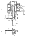
以下、実施例1に係る電動弁10の一実施形態を図面に基づき詳細に説明する。図1は、本発明の実施例1に係る電動弁の最小流量時の状態を示す縦断面図(A)と、同図(A)のb−b断面図(B)であり、図2は、同実施例1に係る電動弁の最大流量時の状態を示す縦断面図(A)と、同図(A)のb−b断面図(B)である。電動弁10は、弁室12a内の弁体13により冷媒の通過流量を調整する弁本体12と、弁本体12と一体で弁体13を回転させるロータ17を内蔵するキャン16と、キャン16に外嵌されロータ17を回転駆動するステータ18とを備えている。ロータ17とステータ18によりステッピングモータを構成している。   Hereinafter, an embodiment of a motor-operated valve 10 according to Example 1 will be described in detail with reference to the drawings. FIG. 1 is a longitudinal sectional view (A) showing a state at the minimum flow rate of the motor-operated valve according to Embodiment 1 of the present invention, and a bb sectional view (B) of FIG. They are a longitudinal cross-sectional view (A) which shows the state at the time of the maximum flow volume of the motor operated valve which concerns on the Example 1, and bb sectional drawing (B) of the same figure (A). The motor-operated valve 10 includes a valve body 12 that adjusts the flow rate of refrigerant through the valve body 13 in the valve chamber 12a, a can 16 that incorporates a rotor 17 that rotates the valve body 13 integrally with the valve body 12, and a can 16 And a stator 18 that is externally fitted and rotationally drives the rotor 17. The rotor 17 and the stator 18 constitute a stepping motor.

弁本体12は本発明の基幹をなすものであり、黄銅等の金属から構成され、図1に示すように、上下に一定長の長さを有し、筒状形状でその筒状内部は弁室12cを形成しており、その側部には弁室12cに連通する第1連通孔12aを有し、該第1連通孔12aには第1流路2aが連結されている。また、弁室の下部には弁室に連通する第2連通孔12bを有し、該第2連通孔12bには第2流路2bが連結されている。弁本体10の上部外周肩部の段差部には、リング状の鍔状板12dが固定される。そして、この鍔状板12dに後述のキャン16の下端部を突き合わせ溶接することにより固定される。   The valve body 12 forms the backbone of the present invention, and is made of a metal such as brass. As shown in FIG. 1, the valve body 12 has a certain length in the vertical direction, and has a cylindrical shape. A chamber 12c is formed, and a side portion thereof has a first communication hole 12a communicating with the valve chamber 12c, and the first flow path 2a is connected to the first communication hole 12a. The lower part of the valve chamber has a second communication hole 12b communicating with the valve chamber, and the second flow path 2b is connected to the second communication hole 12b. A ring-shaped bowl-shaped plate 12 d is fixed to the stepped portion of the upper outer peripheral shoulder of the valve body 10. And it fixes by butt-welding the lower end part of the below-mentioned can 16 to this saddle-like board 12d.

また、図1に示すように、鍔状板12dの上面における中心点から一定角度、例えば180度離れた位置の2箇所にはストッパ12e,12eが立設される。このストッパ12e,12eは、弁体13の回転を一定角度、例えば180度で規制し、弁本体12の第1流路2a及び第2流路2bと位置決め可能に組付けられる。また、ストッパ12e,12eは鍔状板12dと同時にろう付け固定される。弁室12cはその水平断面が円形で略円筒状に形成され、上面が開放され、下面が第2連通部12bに連通し、内部に弁体13が配置される。   Further, as shown in FIG. 1, stoppers 12e and 12e are erected at two positions at a certain angle, for example, 180 degrees apart from the center point on the upper surface of the bowl-shaped plate 12d. The stoppers 12e and 12e are assembled so that the rotation of the valve body 13 is regulated at a constant angle, for example, 180 degrees, and can be positioned with respect to the first flow path 2a and the second flow path 2b of the valve body 12. The stoppers 12e and 12e are brazed and fixed simultaneously with the saddle plate 12d. The valve chamber 12c is formed in a substantially cylindrical shape with a circular horizontal cross section, an upper surface is opened, a lower surface communicates with the second communication portion 12b, and a valve body 13 is disposed therein.

弁体13は黄銅を素材として構成され、一定の厚みを有する筒体からなり、その下部には、弁室12cに内接する外面円筒形状で、この円筒の中心線を軸として回転可能であり、冷媒を第1流路2aと第2流路2bとの間で連通させる弁体流路13が形成されている。実施例1の場合、弁体流路13は、切欠き部13bとオリフィス13aとからなる。切欠き部13bは、図1,2に示すように、弁体13下部の一定高さにわたって、略半円形分が欠けた状態で形成され、更に、弁体13下部の残存部分の上記一定高さの中間位置にオリフィス13aが穿設される。そして、弁体13は回転し、図1に示すように、上記残存部分が第1流路2aを閉止し、オリフィス13aが対向している状態、及び、図2に示すように、上記切欠き部13bが第1流路2aと第2流路2bとを連通させる状態のいずれかに切り換え可能となっている。   The valve body 13 is made of brass and is made of a cylindrical body having a constant thickness. The lower part of the valve body 13 has an outer cylindrical shape inscribed in the valve chamber 12c, and is rotatable around the center line of the cylinder. A valve body flow path 13 is formed to allow the refrigerant to communicate between the first flow path 2a and the second flow path 2b. In the case of Example 1, the valve body flow path 13 consists of the notch part 13b and the orifice 13a. As shown in FIGS. 1 and 2, the notch 13 b is formed in a state in which a substantially semicircular portion is missing over a certain height of the lower part of the valve body 13, and further, the above-mentioned constant height of the remaining part of the lower part of the valve body 13 An orifice 13a is formed at an intermediate position. Then, the valve body 13 is rotated, and as shown in FIG. 1, the remaining portion closes the first flow path 2a and the orifice 13a is opposed, and as shown in FIG. The part 13b can be switched to any state in which the first flow path 2a and the second flow path 2b are communicated.

そのために、弁体13は180度の範囲で回転駆動される。弁体13上部は筒状の弁体キー部13cが形成され、この弁体キー部13cは、後述の弁体ホルダ15に回転のみ連動可能に連結される。そのために、弁体キー部13cの下部外周部は凹凸状に形成され弁体ホルダ15の下部と係合されるようになっている。また、弁体13の上下方向中間位置には段部13dが形成され、弁本体13の上面に当接するように形成され、更に、段部13dの一部には上記ストッパ12e,12eに当接可能な突起部13eが形成されている。   Therefore, the valve body 13 is rotationally driven within a range of 180 degrees. A cylindrical valve body key portion 13c is formed on the upper portion of the valve body 13, and this valve body key portion 13c is connected to a later-described valve body holder 15 so that only rotation is possible. Therefore, the lower outer peripheral portion of the valve body key portion 13c is formed in an uneven shape and is engaged with the lower portion of the valve body holder 15. Further, a step portion 13d is formed at an intermediate position in the vertical direction of the valve body 13, and is formed so as to contact the upper surface of the valve body 13. Further, a part of the step portion 13d contacts the stoppers 12e, 12e. Possible projections 13e are formed.

上記弁体キー部13cは、その上部の筒状の弁体ホルダ15に嵌合される。この弁体ホルダ15はロータ17によって駆動される。弁体ホルダ15はその上面にばね受け部が形成される。また、弁体ホルダ15とロータ17とは支持リング17aを介して結合されており、支持リング17はロータ17の成形時にインサートされた黄銅製の金属リングで構成されている。また、支持リング17の内周孔部に弁体ホルダ15の上部突部が嵌合し、上部突部の外周をかしめ固定して、ロータ17、支持リング17aおよび弁体ホルダ15を結合している。弁本体12、弁体ホルダ15、及び、支持リング17aは、全て黄銅より構成している。   The said valve body key part 13c is fitted by the cylindrical valve body holder 15 of the upper part. This valve element holder 15 is driven by a rotor 17. The valve body holder 15 has a spring receiving portion formed on the upper surface thereof. Further, the valve body holder 15 and the rotor 17 are coupled via a support ring 17 a, and the support ring 17 is composed of a brass metal ring inserted when the rotor 17 is molded. Further, the upper protrusion of the valve element holder 15 is fitted into the inner peripheral hole portion of the support ring 17, and the outer periphery of the upper protrusion is caulked and fixed to couple the rotor 17, the support ring 17 a and the valve element holder 15. The valve body 12, the valve body holder 15, and the support ring 17a are all made of brass.

ロータ17は、後述のキャン16に内装されるように外周面が円筒状であり、弁体ホルダ15に軸支される。また、キャン16の内面上底部と、弁体ホルダ15の上面のばね受けとの間にばね15aが圧装される。この構成により、弁体ホルダ15とロータ17とは下方向において弁体13側に押圧されているが、弁体13に過大な荷重がかかった場合は、弁体ホルダ15と弁体13とが非係合となるようにすることも可能で、安全装置の役割を果たさせることができる。   The rotor 17 has a cylindrical outer peripheral surface so as to be housed in a can 16 described later, and is supported by the valve body holder 15. Further, a spring 15 a is press-fitted between the upper bottom of the inner surface of the can 16 and the spring receiver on the upper surface of the valve element holder 15. With this configuration, the valve element holder 15 and the rotor 17 are pressed toward the valve element 13 in the downward direction, but when an excessive load is applied to the valve element 13, the valve element holder 15 and the valve element 13 are It is also possible to be disengaged, and the role of a safety device can be fulfilled.

キャン16は、ステンレス等の非磁性の金属から形成される有底円筒状をしており、弁本体12の上部に固着されたステンレス製の鍔状板12dに溶接等により固着され、内部は気密状態に保たれている。   The can 16 has a bottomed cylindrical shape made of a non-magnetic metal such as stainless steel, and is fixed to a stainless steel saddle plate 12d fixed to the upper portion of the valve body 12 by welding or the like, and the inside is airtight. It is kept in a state.

ステータ18は、磁性材より構成されるヨーク19と、このヨーク19にボビン19aを介して巻回される上下のステータコイル19b,19bとから構成され、キャン16に外嵌する嵌合穴18aが形成されている。ステータ18には、リード端子19cが配設され、該リード端子19cに接続されるコネクタ19dを覆うカバー19eが形成されている。ステータ18から、ステータコイル19b,19bに接続されたリード端子19cが突出しており、このリード端子19cに複数のリード線19fが接続されたコネクタ19dが連結されている。そして、コネクタ19dを覆うカバー19eがステータ18に溶着され、カバー19e内はエポキシ樹脂等の充填材19gで充填されている。ステータ18は中心に下面開口の嵌合穴18aを有し、この嵌合穴18aにキャン16が嵌合し、ステータ18の下面に溶着された回り止め部材18bにより弁本体12およびキャン16に固定される。   The stator 18 includes a yoke 19 made of a magnetic material, and upper and lower stator coils 19b and 19b wound around the yoke 19 via a bobbin 19a. Is formed. The stator 18 is provided with a lead terminal 19c, and a cover 19e is formed to cover the connector 19d connected to the lead terminal 19c. A lead terminal 19c connected to the stator coils 19b and 19b protrudes from the stator 18, and a connector 19d to which a plurality of lead wires 19f are connected is connected to the lead terminal 19c. A cover 19e covering the connector 19d is welded to the stator 18, and the inside of the cover 19e is filled with a filler 19g such as an epoxy resin. The stator 18 has a fitting hole 18a having a lower surface opening at the center. The can 16 is fitted into the fitting hole 18a, and is fixed to the valve body 12 and the can 16 by a rotation preventing member 18b welded to the lower surface of the stator 18. Is done.

実施例1は、上記構成により、第1,2の両流路2a,2b間で冷媒を流す場合に、弁体13を、図1に示す位置にすれば、小容量の冷媒を流すことができ、弁体13を、図2に示す位置にすれば、大容量の冷媒を流すことができる。この場合、実施例1では,第1流路2aから第2流路2bへ冷媒が流れると、冷媒圧力によって弁体13が右方に押されるため,隙間からの漏れ量が大きく、逆に第2流路2bから第1流路2aへ冷媒が流れると、圧力によって左方向に押されるために隙間からの漏れ量が小さくなる。したがって、オリフィス13aを流れる流量にこの漏れ量がプラスされるために、完全に、第1→第2の流量=第2→第1の流量とになるわけではないが、従来技術のように、触媒の流れの方向により、弁体に対して開閉方向における順方向又は逆方向に冷媒圧が作用しないため、比較的両方向の流れが同一に近いものとなる。また、この実施例1では、電動弁10を構成する部品点数が少ないことから、故障が少なく、また、冷媒の弁体13に対する圧力を、弁本体12が直接的に受けることになるから構造的・応力的に無理がなく、材料的にも節約することができる。   In the first embodiment, when the refrigerant is caused to flow between the first and second flow paths 2a and 2b, the valve body 13 is set to the position shown in FIG. If the valve body 13 is in the position shown in FIG. 2, a large volume of refrigerant can be flowed. In this case, in the first embodiment, when the refrigerant flows from the first flow path 2a to the second flow path 2b, the valve body 13 is pushed rightward by the refrigerant pressure, so that the amount of leakage from the gap is large. When the refrigerant flows from the second flow path 2b to the first flow path 2a, the amount of leakage from the gap is reduced because the refrigerant is pushed leftward by the pressure. Therefore, since this leakage amount is added to the flow rate flowing through the orifice 13a, it is not completely the first → second flow rate = second → first flow rate. Depending on the flow direction of the catalyst, the refrigerant pressure does not act in the forward or reverse direction in the opening / closing direction on the valve body, so the flows in both directions are relatively close to each other. Further, in the first embodiment, since the number of parts constituting the motor-operated valve 10 is small, there are few failures, and the valve body 12 directly receives the pressure of the refrigerant on the valve body 13.・ There is no unreasonable stress, and material can be saved.

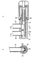
この実施例2の電動弁20では、第1流路2aと第2流路2bを上下に平行に並べて、両流路2a,2bから受ける冷媒からの圧力によって、常に右方向(図3)に押圧される構造として、第1→第2≒第2→第1を実現するものである。実施例2は、図3,4に示し、図3は小容量の状態を、図4は大容量の状態を、それぞれ示している。
実施例2が実施例1と基本的に相違する点は、第1流路2aの下部に平行させて第2流路2bを設けた点、及び、弁体23の第1流路2a及び第2流路2bに対応する弁体23に切欠き部23bを形成すると共に、その残存部分の上下に且つ第1流路2a及び第2流路2bに対応する位置に、それぞれオリフィス23a,23aを穿設した点である。また、弁本体23の下面は閉止されている。
In the motor-operated valve 20 of the second embodiment, the first flow path 2a and the second flow path 2b are arranged in parallel in the vertical direction, and always in the right direction (FIG. 3) due to the pressure from the refrigerant received from both flow paths 2a and 2b. As a structure to be pressed, the first → second≈second → first is realized. The second embodiment is shown in FIGS. 3 and 4, FIG. 3 shows a small capacity state, and FIG. 4 shows a large capacity state.
The second embodiment is basically different from the first embodiment in that the second flow path 2b is provided in parallel with the lower portion of the first flow path 2a, and the first flow path 2a and the first flow path of the valve body 23 are the same. The notch 23b is formed in the valve body 23 corresponding to the two flow paths 2b, and the orifices 23a and 23a are respectively provided above and below the remaining portion and at positions corresponding to the first flow path 2a and the second flow path 2b. This is the point where it was drilled. Further, the lower surface of the valve body 23 is closed.

即ち、実施例2の場合も、弁体流路は、切欠き部23bとオリフィス23a,23aとからなる。切欠き部23bは、図3,4に示すように弁体23下部の一定高さにわたって、略半円形分が欠けた状態で形成され、更に、弁体23下部の残存部分の上記一定高さの位置の2箇所にオリフィス23a,23aが穿設される。なお、弁体23の最下端部は、弁体23の円滑な回転及び支持のために、切り欠かず、平面視正円部分を残すことで、弁本体22に案内させるように形成している。また、この平面視正円部分の中心部分は、中心部に孔を形成したリング状となっている。これは冷媒圧がこの弁体23の下方にかからず、弁本体22の弁室底部に作用させて弁体23の回転の障害とならないようにするためである。   That is, also in the second embodiment, the valve body flow path includes the notch portion 23b and the orifices 23a and 23a. As shown in FIGS. 3 and 4, the notch 23 b is formed in a state in which a substantially semicircular portion is missing over a certain height of the lower part of the valve body 23, and further, the above-mentioned constant height of the remaining part of the lower part of the valve body 23. Orifices 23a, 23a are drilled at two locations. The lowermost end of the valve body 23 is formed so as to be guided to the valve main body 22 by leaving a circular portion in a plan view without leaving a notch for smooth rotation and support of the valve body 23. . Moreover, the center part of this planar view regular-circle part becomes a ring shape which formed the hole in the center part. This is to prevent the refrigerant pressure from being applied below the valve body 23 and acting on the bottom of the valve chamber of the valve body 22 to obstruct the rotation of the valve body 23.

そして、弁体23は回転し、図3に示すように、上記残存部分が第1流路2a及び第1流路2bを閉止し、それぞれのオリフィス23a,23aが第1,2流路2a,2bに対向している状態、及び、図4に示すように、上記切欠き部23bが第1流路2aと第2流路2bとを連通させる状態のいずれかに切り換え可能となっている。
上記構成において、弁体23は180度の範囲で回転駆動される。弁体23上部は筒状の弁体キー部23cが形成され、この弁体キー部23cは、後述のロータ27に回転のみ連動可能に連結されている点、そのために弁体キー部23cの下部外周部は凹凸状に形成され弁体ホルダ25の下部と係合されるようになっている点、及び、弁体23の上下方向中間位置には段部23dが形成され、弁本体22の上面に当接するように形成され、更に、段部23dの一部には上記ストッパ22e,22eに当接可能な突起部23eが形成されている点等は、実施例1と同じである。
Then, the valve body 23 rotates, and as shown in FIG. 3, the remaining portion closes the first flow path 2a and the first flow path 2b, and the respective orifices 23a and 23a are connected to the first and second flow paths 2a, 2a, As shown in FIG. 4, the cutout portion 23 b can be switched to either a state facing the 2 b or a state where the first flow path 2 a and the second flow path 2 b communicate with each other.
In the above configuration, the valve body 23 is driven to rotate within a range of 180 degrees. A cylindrical valve body key portion 23c is formed on the upper portion of the valve body 23, and this valve body key portion 23c is connected to a rotor 27, which will be described later, so that only rotation is possible, and for this reason, a lower portion of the valve body key portion 23c. A step portion 23d is formed at the middle of the valve body 23 in the vertical direction of the valve body 23 in that the outer peripheral portion is formed in an uneven shape and engaged with the lower portion of the valve body holder 25, and the upper surface of the valve body 22 Further, the second embodiment is the same as the first embodiment in that a protrusion 23e that can contact the stoppers 22e and 22e is formed on a part of the step 23d.

実施例2は、実施例1の効果に加えて、冷媒の流れがどのような方向であっても、弁体23は第1流路2aと第2流路2bから受ける圧力によって、常に右方向に押圧される構造となっていることから、冷媒の正・逆の流れ方向に拘わらず実施例1に比べて、一層、第1→第2の流量≒第2→第1の流量、を実現することができる。   In the second embodiment, in addition to the effects of the first embodiment, the valve body 23 is always in the right direction depending on the pressure received from the first flow path 2a and the second flow path 2b regardless of the direction of the flow of the refrigerant. Compared to the first embodiment, the first → second flow rate≈second → first flow rate is realized, regardless of the forward / reverse flow direction of the refrigerant. can do.

本実施例3の電動弁30は、その基本的な課題は実施例1,2と同様とするも、その流路の位置及び弁体構造は基本的に相違する。実施例3では、弁本体32に付設する第1流路2a及び第2流路2bは同一管径で一直線状に配置され、弁体33の回転軸芯を挟んで弁本体32の反対面に連結される。一方、弁体33は全体として筒状に形成される点、及び、弁体33がその回転軸芯部に弁体通路33a,33bが形成されている点などは実施例1,2と変わるところはない。   Although the basic problem of the electric valve 30 of the third embodiment is the same as that of the first and second embodiments, the position of the flow path and the valve body structure are basically different. In the third embodiment, the first flow path 2a and the second flow path 2b attached to the valve main body 32 are arranged in a straight line with the same pipe diameter, and on the opposite surface of the valve main body 32 with the rotation axis of the valve body 33 interposed therebetween. Connected. On the other hand, the point that the valve body 33 is formed in a cylindrical shape as a whole, and the point that the valve body 33 is formed with valve body passages 33a and 33b in the rotating shaft core portion are different from the first and second embodiments. There is no.

この実施例3では、第1流路2aと第2流路2bから受ける冷媒の圧力によって、下流側に押圧されるものの、その形状は全く対称形状となっているために、第1→第2の流量≒第2→第1の流量を実現するものである。実施例3を、更に図5,6を用いて具体的に説明する。図5は小容量の状態を、図6は大容量の状態をそれぞれ示している。実施例3の弁体33の特徴は、弁体流路として流路断面が小さい小オリフィス33aと、流路断面が大きい大オリフィス33bとをクロス状に穿設した点である。また、弁本体32の下面は閉止されている。   In the third embodiment, although it is pressed downstream by the pressure of the refrigerant received from the first flow path 2a and the second flow path 2b, the shape is completely symmetrical, so the first → second The flow rate of ≒ 2nd → 1st flow rate is realized. The third embodiment will be described in detail with reference to FIGS. FIG. 5 shows a small capacity state, and FIG. 6 shows a large capacity state. A feature of the valve element 33 of the third embodiment is that a small orifice 33a having a small flow path section and a large orifice 33b having a large flow path section are formed in a cross shape as valve body flow paths. Further, the lower surface of the valve body 32 is closed.

即ち、実施例3の場合は、弁体流路は、90度に交差する2本の小・大のオリフィス33a,33bとからなる。なお、弁体33の最下端部は、弁体33の円滑な回転及び支持のために、切り欠かず、平面視正円部分を残すことで、弁本体に案内させるように形成している点は、実施例2と同じである。そして、弁体33が、図5に示すように、小オリフィス33aが両流路2a,2bを結ぶ位置にあるときは、第1流路2a、第2流路2b間において冷媒を流す場合に、その方向に拘わらず流量に差は発生しない。また、弁体33をその90度回転させて、図6に示すように、大断面のオリフィス33bが両流路2a,2bを結ぶ位置にあり、第1流路2aから第2流路2bに冷媒を流す場合も、その逆でも流量に差は発生しない。   That is, in the case of Example 3, the valve body flow path is composed of two small and large orifices 33a and 33b that intersect at 90 degrees. The lowermost end of the valve body 33 is formed so as to be guided to the valve main body by leaving a circular part in a plan view without leaving a notch for smooth rotation and support of the valve body 33. Is the same as in Example 2. When the valve body 33 is at a position where the small orifice 33a connects the two flow paths 2a and 2b as shown in FIG. 5, the refrigerant flows between the first flow path 2a and the second flow path 2b. Regardless of the direction, there is no difference in flow rate. Further, by rotating the valve body 33 by 90 degrees, as shown in FIG. 6, the orifice 33b having a large cross section is located at a position connecting both the flow paths 2a and 2b, and the first flow path 2a to the second flow path 2b. There is no difference in the flow rate when the refrigerant is flown or vice versa.

上記構成において、弁体33は90度の範囲で回転駆動される。そして、弁体33上部は筒状の弁体キー部33cが形成され、この弁体キー部33cは、後述のロータ37に回転のみ連動可能に連結されている点、そのために、弁体キー部33cの下部外周部は凹凸状に形成され、ロータ37の下部と係合されるようになっている点、及び、弁体33の上下方向中間位置には段部33dが形成され、弁本体32の上面に当接するように形成され、更に、段部33dの一部には上記ストッパ32eに当接可能な突起部が形成されている点等は、実施例1,2と同じである。   In the above configuration, the valve body 33 is driven to rotate within a range of 90 degrees. A cylindrical valve body key portion 33c is formed on the upper portion of the valve body 33, and this valve body key portion 33c is connected to a rotor 37, which will be described later, so that only rotation is possible. A lower outer peripheral portion of 33c is formed in an uneven shape and is engaged with the lower portion of the rotor 37, and a step portion 33d is formed at an intermediate position in the vertical direction of the valve body 33. The second embodiment is the same as the first and second embodiments in that it is formed so as to be in contact with the upper surface of the first and second protrusions and a protrusion that can contact the stopper 32e is formed on a part of the step 33d.

実施例3は、実施例1の効果に加えて、冷媒の流れがどちらの方向であっても、弁体33が冷媒から受ける圧力は同じであることから、大・小いずれの流量の場合でも、第1→第2の流量=第2→第1の流量となる。   In the third embodiment, in addition to the effects of the first embodiment, the pressure that the valve body 33 receives from the refrigerant is the same regardless of the direction of the flow of the refrigerant. First → second flow rate = second → first flow rate.

この実施例4では、冷媒の入出管2a,2bを構成する2本の流路を弁体43の回転軸芯と平行に縦に並べて、第1流路2aと第2流路2bから受ける冷媒の圧力によって発生する冷媒の漏れ出しを同一にし、第1→第2の流量=第2→第1の流量を実現するものである。   In the fourth embodiment, the two flow paths constituting the refrigerant inlet / outlet pipes 2a and 2b are arranged vertically in parallel with the rotational axis of the valve body 43, and are received from the first flow path 2a and the second flow path 2b. The leakage of the refrigerant generated by the pressure is the same, and the first → second flow rate = second → first flow rate is realized.

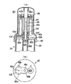
実施例4は図7〜9に示され、図7,9は、流量が小容量の場合を、図8は流量が大容量の場合をそれぞれ示している。具体的には、図7は、冷房(又は暖房)サイクルの除湿時の弁体位置、図8は、冷房・暖房時の弁体位置、図9は、暖冷(又は冷房)サイクルの除湿時の弁体位置を示している。実施例4が実施例1〜3と基本的に相違する点は、図7に示すように、第1流路2aと第2流路2bとを左右に平行に配置し、両流路の上端部に円盤状の弁本体42を配置し、該弁本体42に2つの孔、即ち、第1連通孔42a及び第2連通孔42bを形成して上記流路を装着した点、及び、この弁本体42の上面に180度だけ回転する合成樹脂等から成る弁体を設けた点にある。上記弁体43は蓋状となっており、該蓋部分にはオリフィス43a、即ち、比較的小断面の流通孔が穿設される。   Example 4 is shown in FIGS. 7 to 9, and FIGS. 7 and 9 show the case where the flow rate is a small capacity, and FIG. 8 shows the case where the flow rate is a large capacity. Specifically, FIG. 7 shows the position of the valve body during dehumidification of the cooling (or heating) cycle, FIG. 8 shows the position of the valve body during cooling and heating, and FIG. 9 shows the time of dehumidification during the heating and cooling (or cooling) cycle. The valve body position is shown. The fourth embodiment basically differs from the first to third embodiments in that, as shown in FIG. 7, the first flow path 2a and the second flow path 2b are arranged in parallel on the left and right, and the upper ends of both flow paths. A disc-shaped valve main body 42 is disposed in the portion, and two holes, that is, a first communication hole 42a and a second communication hole 42b are formed in the valve main body 42, and the flow path is mounted. The valve body made of a synthetic resin or the like that rotates by 180 degrees is provided on the upper surface of the main body 42. The valve body 43 has a lid shape, and an orifice 43a, that is, a relatively small cross-sectional flow hole is formed in the lid portion.

更に具体的に述べれば、弁本体42は平面視円形に形成されると共にその中心部には凹部42fが形成され、弁体43の支持軸43cが回転自在に挿通される。この弁体43の外周部及び支持軸43cは、弁体ホルダ3245の内周部に回転力が伝わるように連結されている。上記弁体ホルダ45は、他の実施例と同様にロータ47と一体であり、ロータ47の回転が弁体ホルダ45を介して弁体43を回転させることになる。弁体43は、左・右の第1連通孔42a及び第2連通孔42bを塞ぐことが可能な閉止部43fと軸芯部43gとからなり、該軸芯部43gに支持軸43cが挿通され、該支持軸43cの回転により、閉止部43fは、図7に示す第1連通孔42aを閉止する位置、図8に示す第1連通孔42a及び第2連通孔42b共に閉止しない位置、及び、図9に示す第2連通孔42bを閉止する位置となる。また、弁体43が上記3つの位置以外に移動しないようにするために、2本のストッパ42e,42eが弁本体42上部で連通孔42a,42bの近傍に立設される。   More specifically, the valve main body 42 is formed in a circular shape in plan view, and a concave portion 42f is formed in the center thereof, and the support shaft 43c of the valve body 43 is rotatably inserted. The outer peripheral portion of the valve body 43 and the support shaft 43c are connected to the inner peripheral portion of the valve body holder 3245 so that the rotational force is transmitted. The valve body holder 45 is integrated with the rotor 47 as in the other embodiments, and the rotation of the rotor 47 rotates the valve body 43 via the valve body holder 45. The valve body 43 includes a closing portion 43f and a shaft core portion 43g capable of closing the left and right first communication holes 42a and the second communication hole 42b, and a support shaft 43c is inserted through the shaft core portion 43g. The rotation of the support shaft 43c causes the closing portion 43f to close the first communication hole 42a shown in FIG. 7, the position where both the first communication hole 42a and the second communication hole 42b shown in FIG. 8 do not close, and This is the position for closing the second communication hole 42b shown in FIG. Further, in order to prevent the valve body 43 from moving to other than the above three positions, two stoppers 42e and 42e are erected in the vicinity of the communication holes 42a and 42b on the valve main body 42.

実施例4は、実施例2,3の効果と同様に、冷媒の流れがどちらの方向であっても、弁体43は冷媒圧により連通孔42a,42bに押圧される構造となっていることから、第1→第2の流量=第2→第1の流量を実現することに加えて、弁本体42と弁体43との隙間が小さくなり、冷媒の漏れを僅少にすることができる。具体例においては、図7の冷房サイクル時の除湿時(冷媒は、第2流路から第1流路に流れる。)と、図9の暖房サイクル時の除湿時(冷媒は、第1流路から第2流路に流れる。)とを、略同一の冷媒流状態とすることができる。   In the fourth embodiment, similarly to the effects of the second and third embodiments, the valve body 43 is pressed against the communication holes 42a and 42b by the refrigerant pressure regardless of the direction of the refrigerant flow. Therefore, in addition to realizing the first → second flow rate = second → first flow rate, the gap between the valve main body 42 and the valve body 43 is reduced, and refrigerant leakage can be minimized. In the specific example, at the time of dehumidification during the cooling cycle of FIG. 7 (the refrigerant flows from the second flow path to the first flow path) and at the time of dehumidification during the heating cycle of FIG. 9 (the refrigerant is the first flow path). To the second flow path) can be set to substantially the same refrigerant flow state.

更に、本発明においては、実施例4に示す電動弁において、冷媒通過時に騒音が発生する場合には、その騒音を低減させることができる。即ち、図7〜9に示す電動弁の弁体43に多孔質部材を具備せしめるのである。かかる多孔質部材を具備せしめた実施例5を図10及び図11に示す。   Further, in the present invention, in the motor operated valve shown in the fourth embodiment, when noise is generated when the refrigerant passes, the noise can be reduced. That is, a porous member is provided on the valve body 43 of the motor-operated valve shown in FIGS. A fifth embodiment provided with such a porous member is shown in FIGS.

以下、実施例5に係る電動弁100の一実施形態を図面に基づき詳細に説明する。図10は、実施例5に係る電動弁100の最小流量時の状態を示す縦断面図であり、図11は、図10の矢印α方向からみた弁体位置の説明図である。電動弁100は、弁本体900と、弁本体900と一体で弁体200を回転させるロータ300を内蔵するキャン400と、キャン400に外嵌されロータ300を回転駆動するステータ500とを備えている。ロータ300とステータ500によりステッピングモータを構成している。   Hereinafter, one Embodiment of the motor operated valve 100 which concerns on Example 5 is described in detail based on drawing. FIG. 10 is a longitudinal sectional view showing the state of the motor-operated valve 100 according to the fifth embodiment at the minimum flow rate, and FIG. 11 is an explanatory diagram of the valve body position as seen from the direction of the arrow α in FIG. The motor-operated valve 100 includes a valve body 900, a can 400 that incorporates a rotor 300 that rotates the valve body 200 integrally with the valve body 900, and a stator 500 that is fitted on the can 400 and rotationally drives the rotor 300. . The rotor 300 and the stator 500 constitute a stepping motor.

弁本体900はステンレス等の金属から構成される。回転軸800は、その上部の筒状の弁体ホルダ600に嵌合される。この弁体ホルダ600はロータ300によって駆動される。弁本体900は、その周縁にキャン400の固着部を備えるとともに、弁本体900を構成する円盤部側部で且つ軸線を中心に所定の角度を有する位置に2つの連通孔910,920が配置されている。また、この2つの連通孔910,920には、それぞれ流体入出管2a及び流体入出管2bが連結される。更に、弁本体900の弁室110部分の中心部には、回転軸800の下端を支持する凹部900aが形成される。弁体ホルダ600には、その上面にばね受け部が形成される。また、弁体ホルダ600とロータ300とは支持リング700を介して結合されており、支持リング700はロータ300の成形時にインサートされた金属リングで構成されている。また、支持リング700の内周孔部に弁体ホルダ600の上部突部が嵌合し、上部突部の外周をかしめ固定して、ロータ300、支持リング700および弁体ホルダ600を結合している。   The valve body 900 is made of a metal such as stainless steel. The rotating shaft 800 is fitted into a cylindrical valve body holder 600 on the upper side thereof. The valve body holder 600 is driven by the rotor 300. The valve body 900 includes a fixing portion of the can 400 at the periphery thereof, and two communication holes 910 and 920 are arranged at positions on the side of the disk portion constituting the valve body 900 and having a predetermined angle about the axis. ing. The two communication holes 910 and 920 are connected to the fluid inlet / outlet pipe 2a and the fluid inlet / outlet pipe 2b, respectively. Furthermore, a concave portion 900 a that supports the lower end of the rotating shaft 800 is formed in the central portion of the valve chamber 110 portion of the valve body 900. The valve body holder 600 is formed with a spring receiving portion on the upper surface thereof. Further, the valve body holder 600 and the rotor 300 are coupled via a support ring 700, and the support ring 700 is configured by a metal ring inserted when the rotor 300 is molded. Further, the upper protrusion of the valve element holder 600 is fitted into the inner peripheral hole of the support ring 700, and the outer periphery of the upper protrusion is caulked and fixed to couple the rotor 300, the support ring 700, and the valve element holder 600.

ロータ300は、後述のキャン400に内装されるように外周面が円筒状であり、弁体ホルダ600に軸支される。また、キャン400の内面上底部と、弁体ホルダ600の上面のばね受けとの間にばね820が縮装される。この構成により、弁体ホルダ600とロータ300とは弁本体900側に押圧されている。   The rotor 300 has a cylindrical outer peripheral surface so as to be housed in a can 400 described later, and is supported by the valve body holder 600. Further, the spring 820 is mounted between the upper bottom of the inner surface of the can 400 and the spring receiver on the upper surface of the valve element holder 600. With this configuration, the valve body holder 600 and the rotor 300 are pressed toward the valve body 900.

キャン400は、ステンレス等の非磁性の金属から形成される有底円筒状をしており、弁本体900の上部に形成されたステンレス製の鍔状部分に溶接等により固着され、内部は気密状態に保たれている。   The can 400 has a bottomed cylindrical shape formed of a non-magnetic metal such as stainless steel, and is fixed to a stainless steel bowl-shaped portion formed on the upper portion of the valve body 900 by welding or the like, and the inside is airtight. It is kept in.

ステータ500は、磁性材より構成されるヨーク510と、このヨーク510にボビン520を介して巻回される上下のステータコイル530,530とから構成され、キャン400に外嵌する嵌合孔が形成されている。ステータ500には、リード端子540が配設され、リード端子540に接続されるコネクタ550を覆うカバー560が形成されている。ステータ500からは、ステータコイル530,530に接続されたリード端子540が突出しており、このリード端子540に複数のリード線570が接続されたコネクタ550が連結されている。そして、コネクタ550を覆うカバー560がステータ500に溶着され、カバー560内はエポキシ樹脂等の充填材580で充填されている。ステータ500は中心に下面開口の嵌合孔を有し、この嵌合孔にキャン400が嵌合し、ステータ500の下面に溶着された回り止め部材500aにより弁本体900およびキャン400に固定される。   The stator 500 includes a yoke 510 made of a magnetic material, and upper and lower stator coils 530 and 530 wound around the yoke 510 via a bobbin 520, and a fitting hole that fits outside the can 400 is formed. Has been. The stator 500 is provided with a lead terminal 540 and a cover 560 that covers the connector 550 connected to the lead terminal 540. A lead terminal 540 connected to the stator coils 530 and 530 protrudes from the stator 500, and a connector 550 to which a plurality of lead wires 570 are connected is connected to the lead terminal 540. A cover 560 covering the connector 550 is welded to the stator 500, and the inside of the cover 560 is filled with a filler 580 such as an epoxy resin. The stator 500 has a fitting hole having a lower surface opening at the center. The can 400 is fitted into the fitting hole, and is fixed to the valve main body 900 and the can 400 by a detent member 500a welded to the lower surface of the stator 500. .

弁体200には、図7に示す弁体43の弁体流路43aに多孔質部材を配置し、上記弁体流路43aと同じ流路であるオリフィス224が穿設されたオリフィス形成板225と、多孔質部材として上記オリフィス224の上流側に第1の多孔質部材226を設けている。さらに必要なら、オリフィス224の下流側に第2の多孔質部材を設けてもよい。
図10では、第1及び第2の多孔質部材を配置するために、弁体210に孔221を形成し、この孔221に第1の多孔質部材226、オリフィス224を形成したオリフィス形成板225及び第2の多孔質部材223をこの順に配置し、これらで弁体200の閉止部220を構成する。したがって、弁体200は回転軸800が挿入される軸芯部210と、閉止部220とで構成されることになる。即ち、弁体200は、一定厚みを有し、所定角度離れた第1連通孔910及び第2連通孔920を塞ぐことが可能な閉止部220と、軸芯部210とが例えば合成樹脂等で一体成形されてなり、該軸芯部210に回転軸800が挿通され、該弁体ホルダ600の回転により、閉止部220は、第1連通孔910、及び第2連通孔920共に閉止しない位置、第2連通孔920を閉止する位置、及び第1連通孔910を閉止する位置となる。また、弁体200が上記3つの位置以外に移動しないようにするために、ストッパ930が弁本体900上部に立設される。
In the valve body 200, a porous member is disposed in the valve body flow path 43a of the valve body 43 shown in FIG. 7, and an orifice forming plate 225 in which an orifice 224 that is the same flow path as the valve body flow path 43a is formed. The first porous member 226 is provided on the upstream side of the orifice 224 as a porous member. If necessary, a second porous member may be provided on the downstream side of the orifice 224.
In FIG. 10, in order to arrange the first and second porous members, a hole 221 is formed in the valve body 210, and an orifice forming plate 225 in which a first porous member 226 and an orifice 224 are formed in the hole 221. And the 2nd porous member 223 is arrange | positioned in this order, and the closing part 220 of the valve body 200 is comprised by these. Therefore, the valve body 200 includes the shaft core portion 210 into which the rotating shaft 800 is inserted and the closing portion 220. That is, the valve body 200 has a constant thickness, and the closing portion 220 that can close the first communication hole 910 and the second communication hole 920 separated by a predetermined angle and the shaft core portion 210 are made of, for example, synthetic resin. The rotary shaft 800 is inserted into the shaft core portion 210, and the closing portion 220 does not close both the first communication hole 910 and the second communication hole 920 due to the rotation of the valve body holder 600. It becomes a position for closing the second communication hole 920 and a position for closing the first communication hole 910. Further, in order to prevent the valve body 200 from moving to other than the above three positions, a stopper 930 is erected on the upper part of the valve main body 900.

軸芯部210には棒状の連動杆211が立設され、該連動杆211は回転軸800側に形成された略U形の駆動板810により前後から挟まれるように配置されている。なお、連動杆211を略U形に形成し、駆動板810を平板状に形成して、連動杆211が駆動板810を前後から挟むように配置しても同様の機能が得られる。   A rod-shaped interlocking rod 211 is erected on the shaft core portion 210, and the interlocking rod 211 is disposed so as to be sandwiched from the front and rear by a substantially U-shaped drive plate 810 formed on the rotating shaft 800 side. The same function can be obtained even if the interlocking rod 211 is formed in a substantially U shape, the drive plate 810 is formed in a flat plate shape, and the interlocking rod 211 is disposed so as to sandwich the drive plate 810 from the front and rear.

閉止部220は、その位置により、第1連通孔910又は第2連通孔920のいずれか、若しくは、両方を開とする作用を有する。(図10,11は、第1連通孔910を「閉」とし、流体が流体入出管2bから流体入出管2aに流れる場合を示している。)弁体200の閉止部220には孔221が形成され、該孔221には支持段部222が形成される。そして、この支持段部222上には、第2多孔質部材223、オリフィス224が穿設されたオリフィス形成板225、及び、第1多孔質部材226がこの順で嵌合され、前記各部材223,225,226が固定部材227によって孔221内に固定される。   The closing part 220 has an action of opening either the first communication hole 910 or the second communication hole 920 or both, depending on the position. (FIGS. 10 and 11 show the case where the first communication hole 910 is “closed” and the fluid flows from the fluid inlet / outlet pipe 2b to the fluid inlet / outlet pipe 2a.) A hole 221 is formed in the closing portion 220 of the valve body 200. The support step 222 is formed in the hole 221. On the support step 222, a second porous member 223, an orifice forming plate 225 in which an orifice 224 is formed, and a first porous member 226 are fitted in this order, and each member 223 is fitted. , 225, 226 are fixed in the hole 221 by a fixing member 227.

上流側の第1多孔質部材226は、ニッケル、銅などを主成分とする発泡金属或いは多孔質プラスチックを円盤状に形成し、これをオリフィス形成板225の上流側の孔221に嵌合させる。もちろん、オリフィス224部分のみを覆うようにしてもよい。発泡金属は気孔率が90%以上のものが望ましい。また、第1多孔質部材226が層形状である場合は、2層以上の構造としても良い。   The first porous member 226 on the upstream side is formed of a foam metal or porous plastic mainly composed of nickel, copper or the like in a disc shape, and is fitted into the hole 221 on the upstream side of the orifice forming plate 225. Of course, only the orifice 224 portion may be covered. The foam metal preferably has a porosity of 90% or more. Moreover, when the 1st porous member 226 is a layer shape, it is good also as a structure of two or more layers.

下流側の第2多孔質部材223は、上流側の第1多孔質部材226と同様に、ニッケル、銅などを主成分とする発泡金属或いは多孔質プラスチックを円盤状に形成し、これをオリフィス形成板225の下流側の孔121に嵌合させる。また、第2多孔質部材223が層形状である場合は、2層以上の構造としても良い。更に、以上の説明においては、多孔質部材について述べたが、上記第1及び第2の多孔質部材226,223の一方又は両方をメッシュ状の金網部材に変更してもよいのは勿論である。
上記実施例5によれば、多孔質部材、例えば発泡金属の形成体又は多孔質プラスチックの成形体からなる部材が介装されているので、流体中の大きな気泡は、多孔質部材を通過する際に細分化され、その細分化された状態で、大きな気泡に成長することなく速やかに弁体と流出口との間に形成されるオリフィスに流入する。そして、流出口(オリフィス)を通過する際、その流入側と流出側に急激な圧力変動は発生せず、したがって、従来の電動弁に比して、流動音の低減効果が向上し、騒音を効果的に防止できる。なお、実施例5は、第1連通孔910と第2連通孔920とが、軸線を中心に所定角度を有する位置に配置する場合の実施例を示したが、この配置角度は、本発明の作用効果が実現する限りにおいて適宜選択される。
The second porous member 223 on the downstream side, like the first porous member 226 on the upstream side, is formed by forming a foamed metal or porous plastic mainly composed of nickel, copper, etc. into a disk shape, and forming this into an orifice. It fits in the hole 121 on the downstream side of the plate 225. Moreover, when the 2nd porous member 223 is a layer shape, it is good also as a structure of two or more layers. Furthermore, in the above description, the porous member has been described. However, it is needless to say that one or both of the first and second porous members 226 and 223 may be changed to a mesh-like wire mesh member. .
According to the fifth embodiment, since a porous member, for example, a member made of a foamed metal formed body or a porous plastic molded body is interposed, large bubbles in the fluid pass through the porous member. In the subdivided state, it quickly flows into an orifice formed between the valve body and the outlet without growing into a large bubble. And, when passing through the outlet (orifice), there is no sudden pressure fluctuation on the inflow side and outflow side, so that the effect of reducing the flow noise is improved compared to the conventional motorized valve, and the noise is reduced. It can be effectively prevented. In addition, although Example 5 showed the Example when the 1st communicating hole 910 and the 2nd communicating hole 920 arrange | position in the position which has a predetermined angle centering on an axis line, this arrangement | positioning angle shows the present invention. It is appropriately selected as long as the effect is realized.

実施例6に係る電動弁50は、第1流路2aと第2流路2bとが、弁本体52を構成する円盤部の軸線延長部側部で且つ軸線を中心に一定の角度を有する位置に配置されることを特徴とする(図12〜14)。換言すれば、実施例4では、弁本体52の中心に対して、2つの連通孔52a,52bを点対称の位置に、即ち、弁本体52の中心に対して180度離して配置させたが、実施例6では、135度離して配置し、この2つの連通孔52a,52bに第1流路2aと第2流路2bを設けるものである。   In the motor-operated valve 50 according to the sixth embodiment, the first flow path 2a and the second flow path 2b are located on the side of the axial extension portion of the disk portion constituting the valve body 52 and have a certain angle around the axis. (FIGS. 12 to 14). In other words, in the fourth embodiment, the two communication holes 52 a and 52 b are arranged at point-symmetric positions with respect to the center of the valve body 52, that is, 180 degrees apart from the center of the valve body 52. In the sixth embodiment, the first flow path 2a and the second flow path 2b are provided in the two communication holes 52a and 52b by being spaced apart by 135 degrees.

具体的に述べれば、図12〜14に示すように、弁本体52は平面視円形に形成されると共に、その中心部には凹部52fが形成され、弁体53の支持軸53cが回転自在に挿通される。この弁体53は、弁体ホルダ55に嵌合され、回転力が伝わるように連結されている。上記弁体ホルダ55は、他の実施例と同様にロータ57と一体であり、ロータ57の回転が弁体ホルダ55を介して弁体53を回転させることになる。なお、キャン56はキャン支持枠52dを介して弁体52に支持・固定されている。弁体53は、135度離れた第1連通孔52a、及び第2連通孔52bを塞ぐことが可能な閉止部53fと軸芯部53gとからなり、該軸芯部53gに支持軸53cが挿通され、該弁体ホルダ55の回転により、閉止部53fは、図12に示す第1連通孔52a、及び第2連通孔52b共に閉止しない位置、図13に示す第2連通孔52bを閉止する位置、及び図14に示す第1連通孔52aを閉止する位置となる。また、弁体53が上記3つの位置以外に移動しないようにするために、1本のストッパ52eが弁本体52上部に立設される。   Specifically, as shown in FIGS. 12 to 14, the valve body 52 is formed in a circular shape in plan view, and a recess 52 f is formed at the center thereof, so that the support shaft 53 c of the valve body 53 is rotatable. It is inserted. The valve body 53 is fitted to the valve body holder 55 and connected so that rotational force is transmitted. The valve body holder 55 is integral with the rotor 57 as in the other embodiments, and the rotation of the rotor 57 rotates the valve body 53 via the valve body holder 55. The can 56 is supported and fixed to the valve body 52 via a can support frame 52d. The valve body 53 includes a closing portion 53f and a shaft core portion 53g capable of closing the first communication hole 52a and the second communication hole 52b separated by 135 degrees, and the support shaft 53c is inserted into the shaft core portion 53g. Then, by the rotation of the valve body holder 55, the closing portion 53f does not close both the first communication hole 52a and the second communication hole 52b shown in FIG. 12, and closes the second communication hole 52b shown in FIG. And it becomes a position which closes the 1st communicating hole 52a shown in FIG. Further, in order to prevent the valve body 53 from moving to other than the above three positions, one stopper 52e is erected on the valve main body 52.

実施例6は、実施例4,5の効果と同様に、冷媒の流れがどちらの方向であっても、弁体53は冷媒圧により、第1連通孔52a又は第2連通孔52bに押圧される構造となっていることから、第1→第2の流量=第2→第1の流量を実現することに加えて、弁本体と弁体との隙間が小さくなり、冷媒の漏れを僅少にすることができる。特に、本実施例6は、図12の状態では、双方向で全開、図13の状態では、第1流路→第2流路の方向で全閉、図14の状態では、第2流路→第1流路の方向で全閉となる。   In the sixth embodiment, similar to the effects of the fourth and fifth embodiments, the valve body 53 is pressed against the first communication hole 52a or the second communication hole 52b by the refrigerant pressure regardless of which direction the refrigerant flows. Therefore, in addition to realizing the first → second flow rate = second → first flow rate, the gap between the valve body and the valve body is reduced, and refrigerant leakage is reduced. can do. In particular, the sixth embodiment is fully open in both directions in the state of FIG. 12, fully closed in the direction of the first flow path → second flow path in the state of FIG. 13, and the second flow path in the state of FIG. → Fully closed in the direction of the first flow path.

具体例には、図13の冷房サイクル時の除湿時(冷媒は、第1流路2aから第2流路2bに流れる。)と、図14の暖房サイクル時の除湿時(冷媒は、第2流路2bから第1流路2aに流れる。)とを、略同一の冷媒流状態とすることができる。更に、実施例6では、第1流路2aと第2流路2bとを近接して設けることができ、外形がコンパクトになるとともに、弁室52c内における冷媒の移動が少なく、抵抗も少ないから、弁室52c内における冷媒の移動エネルギの損失も少なくて済むという効果もある。   Specific examples include dehumidification during the cooling cycle of FIG. 13 (the refrigerant flows from the first flow path 2a to the second flow path 2b) and dehumidification during the heating cycle of FIG. The flow from the flow path 2b to the first flow path 2a) can be substantially the same refrigerant flow state. Further, in the sixth embodiment, the first flow path 2a and the second flow path 2b can be provided close to each other, the outer shape becomes compact, the movement of the refrigerant in the valve chamber 52c is small, and the resistance is also small. There is also an effect that the loss of the moving energy of the refrigerant in the valve chamber 52c can be reduced.

なお、上記各実施例においては、小容量の流量を流すために、弁体流路として、オリフィスを形成したが、実施例5のように、弁体にオリフィスを形成しなければ流量を限りなくゼロに近い値となる。   In each of the above-described embodiments, an orifice is formed as a valve body flow path in order to flow a small volume flow rate. However, as in the fifth embodiment, the flow rate is not limited unless an orifice is formed in the valve body. The value is close to zero.

本発明の実施例1に係る電動弁の最小流量時の状態を示す縦断面図(A)と、同図(A)のb−b断面図(B)。The longitudinal cross-sectional view (A) which shows the state at the time of the minimum flow volume of the motor operated valve which concerns on Example 1 of this invention, and bb sectional drawing (B) of the same figure (A). 同実施例1に係る電動弁の最大流量時の状態を示す縦断面図(A)と、同図(A)のb−b断面図(B)。The longitudinal cross-sectional view (A) which shows the state at the time of the maximum flow volume of the motor operated valve which concerns on the Example 1, and bb sectional drawing (B) of the same figure (A). 本発明の実施例2に係る電動弁の最小流量時の状態を示す要部縦断面図(A)と、同図(A)のb−b断面図(B)。The principal part longitudinal cross-sectional view (A) which shows the state at the time of the minimum flow volume of the motor operated valve which concerns on Example 2 of this invention, and bb sectional drawing (B) of the same figure (A). 同実施例2に係る電動弁の最大流量時の状態を示す要部縦断面図(A)と、同図(A)のb−b断面図(B)。The principal part longitudinal cross-sectional view (A) which shows the state at the time of the maximum flow volume of the motor operated valve which concerns on the Example 2, and bb sectional drawing (B) of the same figure (A). 本発明の実施例3に係る電動弁の最小流量時の状態を示す要部縦断面図(A)と、同図(A)のb−b断面図(B)。The principal part longitudinal cross-sectional view (A) which shows the state at the time of the minimum flow volume of the motor operated valve which concerns on Example 3 of this invention, and bb sectional drawing (B) of the same figure (A). 同実施例3に係る電動弁の最大流量時の状態を示す要部縦断面図(A)と、同図(A)のb−b断面図(B)。The principal part longitudinal cross-sectional view (A) which shows the state at the time of the maximum flow volume of the motor operated valve which concerns on the Example 3, and bb sectional drawing (B) of the same figure (A). 本発明の実施例4に係る電動弁の正方向の最小流量時の要部縦断面図(A)と弁体位置説明図(B)。The principal part longitudinal cross-sectional view at the time of the minimum flow rate of the positive direction of the motor operated valve which concerns on Example 4 of this invention (A), and valve body position explanatory drawing (B). 同実施例4に係る電動弁の最大流量時の要部縦断面図(A)と弁体位置説明図(B)。The principal part longitudinal cross-sectional view (A) at the time of the maximum flow volume of the motor operated valve which concerns on the same Example 4, and valve body position explanatory drawing (B). 同実施例4に係る電動弁の逆方向の最小流量時の要部縦断面図(A)と弁体位置説明図(B)。The principal part longitudinal cross-sectional view (A) at the time of the minimum flow rate of the reverse direction of the electrically operated valve which concerns on the Example 4 and valve body position explanatory drawing (B). 本発明の実施例5に係る電動弁の最小流量時の状態を示す縦断面図。The longitudinal cross-sectional view which shows the state at the time of the minimum flow volume of the motor operated valve which concerns on Example 5 of this invention. 図10の矢印α方向からみた弁体位置の説明図。Explanatory drawing of the valve body position seen from the arrow (alpha) direction of FIG. 本発明の実施例6に係る電動弁の最大流量時の要部縦断面図(A)と弁体位置説明図(B)。なお、図(A)は、図(B)のD−D断面。The principal part longitudinal cross-sectional view (A) at the time of the maximum flow volume of the motor operated valve which concerns on Example 6 of this invention, and valve body position explanatory drawing (B). In addition, FIG. (A) is a DD cross section of FIG. (B). 同実施例6に係る電動弁の逆方向の最小流量時の要部縦断面図(A)と弁体位置説明図(B)。なお、図(A)は、図(B)のD−D断面。The principal part longitudinal cross-sectional view (A) at the time of the minimum flow rate of the reverse direction of the motor operated valve which concerns on the Example 6 and valve body position explanatory drawing (B). In addition, FIG. (A) is a DD cross section of FIG. (B). 同実施例6に係る電動弁の正方向の最小流量時の要部縦断面図(A)と弁体位置説明図(B)。なお、図(A)は、図(B)のD−D断面。The principal part longitudinal cross-sectional view (A) at the time of the minimum flow rate of the positive direction of the motor operated valve which concerns on the Example 6 and valve body position explanatory drawing (B). In addition, FIG. (A) is a DD cross section of FIG. (B). 従来技術に係る電動弁の縦断面図。The longitudinal cross-sectional view of the motor operated valve which concerns on a prior art.

符号の説明Explanation of symbols

1・・・電動弁(従来技術),2・・・弁本体
2a・・・流体入出管[第1流路],2b・・・流体入出管[第2流路]
2c・・・弁室,2d・・・ガイドブッシュ固定部
2e・・・キャン固着部,2f・・・弁座
3・・・弁軸,3a・・・弁体
3b・・・圧縮コイルばね,3c・・・プッシュナット
4・・・ガイドブッシュ
4a・・・雌ねじ部,4b・・・下ストッパ
5・・・弁体ホルダ
5a・・・雄ねじ部,5b・・・上ストッパ
6・・・キャン,7・・・ロータ
8・・・ステータ,8a・・・ステータコイル
8b・・・ヨーク,8c・・・リード線
8d・・・コネクタ,8e・・・カバー
10・・電動弁(実施例1)
12・・弁本体,12a・・第1連通孔
12b・・第2連通孔,12c・・弁室
12d・・鍔状板,12e・・ストッパ
13・・・・弁体,13a・・弁体流路[オリフィス]
13b・・弁体流路[切欠き部],13c・・弁体キー部
13d・・段部,13e・・突起部
15・・弁体ホルダ,15a・・ばね
16・・キャン
17・・ロータ,17a・・支持リンク
18・・ステータ,18a・・嵌合穴
18b・・回り止め部材
19・・ヨーク,19a・・ボビン
19b・・ステータコイル,19c・・リード端子
19d・・コネクタ,19e・・カバー
19f・・リード線,19g・・充填材
20・・電動弁(実施例2)
22・・弁本体,22a・・第1連通孔
22b・・第2連通孔,22c・・弁室
22d・・鍔状板,22e・・ストッパ
23・・・・弁体,23a・・弁体流路[オリフィス]
23b・・弁体流路[切欠き部],23c・・弁体キー部
23d・・段部,23e・・突起部
25・・弁体ホルダ,25a・・ばね
26・・キャン
27・・ロータ,27a・・支持リンク,30・・電動弁(実施例3)
32・・弁本体,32a・・第1連通孔
32b・・第2連通孔,32c・・弁室
32d・・鍔状板,32e・・ストッパ
33・・・・弁体,33a・・弁体流路[小オリフィス]
33b・・弁体流路[大オリフィス],33c・・弁体キー部
33d・・段部,33e・・突起部
35・・弁体ホルダ,35a・・ばね
36・・キャン
37・・ロータ,37a・・支持リンク
40・・電動弁(実施例4)
42・・弁本体,42a・・第1連通孔
42b・・第2連通孔,42c・・弁室
42e・・ストッパ,42f・・凹部
43・・・・弁体,43a・・弁体流路[オリフィス]
43c・・支持軸,43d・・段部
43f・・閉止部,43g・・軸芯部
45・・弁体ホルダ,45a・・ばね
46・・キャン
47・・ロータ,47a・・支持リンク
50・・電動弁(実施例6)
52・・弁本体,52a・・第1連通孔
52b・・第2連通孔,52c・・弁室
52d・・キャン支持枠,52e・・ストッパ
52f・・凹部,53・・・・弁体,53c・・支持軸
53e・・突起部,53f・・閉止部,53g・・軸芯部
55・・弁体ホルダ,55a・・ばね,56・・キャン
57・・ロータ,57a・・支持リンク
100・・電動弁(実施例5),110・・弁室
200・・弁体,210・・軸芯部
211・・連動杆,220・・閉止部
221・・孔,222・・支持段部
223・・第2多孔質部材,224・・オリフィス
225・・オリフィス形成板,226・・第1多孔質部材
227・・固定部材,300・・ロータ
400・・キャン,500・・ステータ,500a・・回り止め部材
510・・ヨーク,520・・ボビン
530・・ステータコイル,540・・リード端子
550・・コネクタ,560・・カバー
570・・リード線,580・・充填材
600・・弁体ホルダ,700・・支持リング
800・・回転軸,810・・・駆動板
820・・ばね,900・・・弁本体
910・・・第1連通孔,920・・・第2連通孔
930・・・ストッパ
DESCRIPTION OF SYMBOLS 1 ... Electric valve (prior art), 2 ... Valve main body 2a ... Fluid inlet / outlet pipe [1st flow path], 2b ... Fluid inlet / outlet pipe [2nd flow path]
2c: Valve chamber, 2d: Guide bush fixing portion 2e: Can fixing portion, 2f: Valve seat 3: Valve shaft, 3a: Valve body 3b: Compression coil spring, 3c ... Push nut 4 ... Guide bush 4a ... Female thread part, 4b ... Lower stopper 5 ... Valve element holder 5a ... Male thread part, 5b ... Upper stopper 6 ... Can 7 ... rotor 8 ... stator, 8a ... stator coil 8b ... yoke, 8c ... lead wire 8d ... connector, 8e ... cover 10,. )
12 .. Valve body, 12a ... First communication hole 12b ... Second communication hole, 12c ... Valve chamber 12d, saddle plate, 12e ... Stopper 13 ... Valve body, 13a ... Valve body Flow path [orifice]
13b ... Valve flow path [notch], 13c ... Valve key part 13d ... Step part 13e ... Projection part 15 ... Valve holder 15a ... Spring 16 ... Can 17 ... Rotor , 17a ··· Support link 18 ··· Stator 18a · · Fitting hole 18b · · Anti-rotation member 19 · · yoke 19a · bobbin 19b · stator coil 19c · · lead terminal 19d · connector · 19e · · Cover 19f · · Lead wire 19g · · Filler 20 · · Electric valve (Example 2)
··· Valve body, 22a ··· First communication hole 22b · ··· Second communication hole, 22c · · Valve chamber 22d · · · Plate, 22e · · · Stopper 23 · · · Valve body, 23a · · · valve body Flow path [orifice]
23b ... Valve flow path [notch part] 23c ... Valve key part 23d ... Step part 23e ... Protrusion 25 ... Valve holder 25a ... Spring 26 ... Can 27 ... Rotor 27a ... Support link, 30 ... Electric valve (Example 3)
32 ... Valve body, 32a ... First communication hole 32b ... Second communication hole, 32c ... Valve chamber 32d ... Saddle plate, 32e ... Stopper 33 ... Valve, 33a ... Valve Flow path [small orifice]
33b ... Valve flow path [Large orifice] 33c ... Valve key part 33d ... Step part 33e ... Protrusion 35 ... Valve holder 35a ... Spring 36 ... Can 37 ... Rotor 37a .. Support link 40 .. Motorized valve (Example 4)
42 ... Valve body 42a ... First communication hole 42b ... Second communication hole 42c ... Valve chamber 42e ... Stopper 42f ... Recess 43 ... Valve, 43a ... Valve flow path [Orifice]
43c ··· Support shaft, 43d · · Step portion 43f · · Closing portion, 43g · · Shaft core portion 45 · · Valve body holder, 45a · · · Spring 46 · · · Can 47 · · · Rotor, 47a · · · Support link 50 · ·・ Electric valve (Example 6)
52 ... Valve body 52a ... First communication hole 52b ... Second communication hole 52c ... Valve chamber 52d ... Can support frame 52e ... Stopper 52f ... Recess part 53 ... Valve 53c ... Support shaft 53e ... Projection part 53f ... Closure part 53g ... Shaft core 55 ... Valve body holder 55a ... Spring 56 ... Can 57 ... Rotor 57a ... Support link 100 ..Motorized valve (Embodiment 5), 110 ..Valve chamber 200 ..Valve body 210 ..Axis core part 211 ..Interlocking rod 220 ..Closed part 221 ..Hole 222 ..Supporting step part 223 .. second porous member 224 .. orifice 225 .. orifice forming plate 226 .. first porous member 227 .. fixing member 300 .. rotor 400 .. can 500 .. stator 500a. Non-rotating member 510 ・ ・ Yoke, 520 ・Bobbin 530 ··· Stator coil 540 · · Lead terminal 550 · · Connector 560 · · Cover 570 · · Lead wire 580 · · Filler 600 · · Valve body holder 700 · · Support ring 800 · · Rotating shaft 810 ... Drive plate 820 ... Spring, 900 ... Valve body 910 ... First communication hole, 920 ... Second communication hole 930 ... Stopper

Claims (13)

弁室内の弁体により流体の通過流量を調整する弁本体と、該弁本体に固着され前記弁体を作動させるロータを内蔵するキャンと、該キャンに外嵌され前記ロータを回転駆動するステータとを備えた電動弁において、前記弁体は、回転可能とし、流体の流れ方向が正逆いずれに拘わらず、流量が略同一となるように構成することを特徴とする電動弁。   A valve body that adjusts the flow rate of fluid by a valve body in the valve chamber; a can that is fixed to the valve body and that houses a rotor that operates the valve body; and a stator that is externally fitted to the can and rotationally drives the rotor. The motor-operated valve is characterized in that the valve body is configured to be rotatable so that the flow rate is substantially the same regardless of whether the fluid flow direction is normal or reverse. 弁本体と、該弁本体に固着されるキャンと、該キャンに嵌合されるロータとを備えた電動弁において、前記弁本体の弁室内にはロータに連動して回転する弁体を設け、流体の流れ方向が正逆いずれに拘わらず、流体の圧力に伴って形成される弁本体と弁体との隙間の大きさが略同一となるように構成することを特徴とする電動弁。   In a motor-operated valve comprising a valve body, a can fixed to the valve body, and a rotor fitted to the can, a valve body that rotates in conjunction with the rotor is provided in the valve chamber of the valve body, What is claimed is: 1. A motor-operated valve configured to have substantially the same size of a gap between a valve body and a valve body formed in accordance with fluid pressure, regardless of whether the fluid flow direction is normal or reverse. 弁体は、外面円筒形状でこの円筒の中心線を軸として回転するようにし、弁体には流体を両流路間で連通させる弁体流路を形成することを特徴とする請求項1又は2記載の電動弁。   2. The valve body according to claim 1, wherein the valve body has an outer cylindrical shape and is rotated about the center line of the cylinder, and the valve body is formed with a valve body flow path that allows fluid to communicate between both flow paths. 2. The electric valve according to 2. 弁体に弁体流路を複数設け、それぞれの弁体流路の断面積が相違するように形成することを特徴とする請求項3記載の電動弁。   4. The motor-operated valve according to claim 3, wherein a plurality of valve body flow paths are provided in the valve body, and the cross-sectional areas of the valve body flow paths are different from each other. 弁本体は、弁本体に連結される第1流路と第2流路とが直角に配置されるように形成することを特徴とする請求項1乃至4に記載のいずれかの電動弁。   5. The motor-operated valve according to claim 1, wherein the valve main body is formed such that the first flow path and the second flow path connected to the valve main body are arranged at right angles. 弁本体は、弁本体に連結される第1流路と第2流路とが円筒部側部で並行して配置されるように形成することを特徴とする請求項3又は4に記載のいずれかの電動弁。   The valve body is formed so that the first flow path and the second flow path connected to the valve main body are arranged in parallel on the side of the cylindrical portion. A motorized valve. 弁本体は、弁本体に連結される第1流路と第2流路とが略直線状に配置され、且つ、弁体流路は弁体を貫通するように形成することを特徴とする請求項3又は4に記載のいずれかの電動弁。   The valve body is characterized in that the first flow path and the second flow path connected to the valve main body are arranged substantially linearly, and the valve body flow path is formed so as to penetrate the valve body. Item 5. The motor-operated valve according to any one of items 3 and 4. 弁本体は、弁本体に連結される第1流路と第2流路とが円筒部の軸線延長部の側部に略並行して配置されるように形成することを特徴とする請求項3又は4記載の電動弁。   The valve main body is formed so that the first flow path and the second flow path connected to the valve main body are arranged substantially in parallel with the side portion of the axial extension portion of the cylindrical portion. Or the motor operated valve of 4. 弁本体は円盤状部材からなり、該円盤状部材の中心部周辺に第1連通孔と第2連通孔とが穿設されると共に、円盤状部材のキャン側に、回転して第1連通孔と第2連通孔とを選択的に閉止する位置、及び、第1連通孔と第2連通孔の両方とも閉止しない位置とに移動可能に弁体が配置され、更に、円盤状部材の弁体を配置した側とは反対側の各連通孔に、第1流路と第2流路とを装着させることを特徴とする請求項8に記載の電動弁。   The valve body is made of a disk-shaped member, and a first communication hole and a second communication hole are formed around the center of the disk-shaped member, and the first communication hole is rotated to the can side of the disk-shaped member. And the second communication hole are selectively closed, and the valve body is arranged to be movable to a position where both the first communication hole and the second communication hole are not closed. The motor-operated valve according to claim 8, wherein the first flow path and the second flow path are attached to each of the communication holes on the side opposite to the side where the valve is disposed. 第1連通孔と第2連通孔とは、円筒部の軸線延長部側部で且つ軸線を中心に所定の角度を有する位置に配置することを特徴とする請求項9記載の電動弁。   The motor-operated valve according to claim 9, wherein the first communication hole and the second communication hole are arranged on the side of the axial extension portion of the cylindrical portion and at a position having a predetermined angle about the axis. 上記弁体の弁体流路の上流側に多孔質部材を配置せしめたことを特徴とする請求項9記載の電動弁。   10. The motor-operated valve according to claim 9, wherein a porous member is disposed upstream of the valve body flow path of the valve body. 上記弁体は、孔及びこの孔内にオリフィスを形成したオリフィス形成板を具備すると共に、上記多孔質部材は、上記オリフィス形成板における流体流入側に配置されていることを特徴とする請求項11記載の電動弁。   12. The valve body includes a hole and an orifice forming plate in which an orifice is formed in the hole, and the porous member is disposed on a fluid inflow side of the orifice forming plate. The motorized valve described. 上記孔に支持段部を形成し、この支持段部に多孔質部材、オリフィス形成板をこの順に固定する固定部材を設けたことを特徴とする請求項12記載の電動弁。   The motor-operated valve according to claim 12, wherein a support step portion is formed in the hole, and a fixing member for fixing the porous member and the orifice forming plate in this order is provided in the support step portion.
JP2008200482A 2008-08-04 2008-08-04 Motor-operated selector valve Abandoned JP2008292003A (en)

Priority Applications (1)

Application Number Priority Date Filing Date Title
JP2008200482A JP2008292003A (en) 2008-08-04 2008-08-04 Motor-operated selector valve

Applications Claiming Priority (1)

Application Number Priority Date Filing Date Title
JP2008200482A JP2008292003A (en) 2008-08-04 2008-08-04 Motor-operated selector valve

Related Parent Applications (1)

Application Number Title Priority Date Filing Date
JP2001314860A Division JP4190751B2 (en) 2001-10-12 2001-10-12 Electric switching valve

Publications (1)

Publication Number Publication Date
JP2008292003A true JP2008292003A (en) 2008-12-04

Family

ID=40166918

Family Applications (1)

Application Number Title Priority Date Filing Date
JP2008200482A Abandoned JP2008292003A (en) 2008-08-04 2008-08-04 Motor-operated selector valve

Country Status (1)

Country Link
JP (1) JP2008292003A (en)

Cited By (3)

* Cited by examiner, † Cited by third party
Publication number Priority date Publication date Assignee Title
CN104079105A (en) * 2013-03-28 2014-10-01 日本电产三协株式会社 Outer cover structure of motor
CN110296264A (en) * 2018-03-23 2019-10-01 浙江三花智能控制股份有限公司 Electric expansion valve
JP2022168601A (en) * 2021-04-26 2022-11-08 株式会社鷺宮製作所 valve device

Citations (8)

* Cited by examiner, † Cited by third party
Publication number Priority date Publication date Assignee Title
JPH01152176U (en) * 1988-04-12 1989-10-20
JPH02159485A (en) * 1988-12-13 1990-06-19 Matsushita Electric Ind Co Ltd Electromagnetic valve
JPH02141778U (en) * 1989-05-02 1990-11-29
JPH0328583A (en) * 1989-06-23 1991-02-06 Ranco Japan Ltd Branching valve
JP2000314575A (en) * 1999-04-28 2000-11-14 Mitsubishi Electric Corp Flow control valve, air conditioner and multi-room air conditioner
JP2001050615A (en) * 1999-08-06 2001-02-23 Mitsubishi Electric Corp Aperture device
JP2001235049A (en) * 2000-02-22 2001-08-31 Fuji Koki Corp Motor-driven selector valve
JP2003090650A (en) * 2001-09-18 2003-03-28 Mitsubishi Electric Corp Flow control device, refrigeration cycle device and air conditioner

Patent Citations (8)

* Cited by examiner, † Cited by third party
Publication number Priority date Publication date Assignee Title
JPH01152176U (en) * 1988-04-12 1989-10-20
JPH02159485A (en) * 1988-12-13 1990-06-19 Matsushita Electric Ind Co Ltd Electromagnetic valve
JPH02141778U (en) * 1989-05-02 1990-11-29
JPH0328583A (en) * 1989-06-23 1991-02-06 Ranco Japan Ltd Branching valve
JP2000314575A (en) * 1999-04-28 2000-11-14 Mitsubishi Electric Corp Flow control valve, air conditioner and multi-room air conditioner
JP2001050615A (en) * 1999-08-06 2001-02-23 Mitsubishi Electric Corp Aperture device
JP2001235049A (en) * 2000-02-22 2001-08-31 Fuji Koki Corp Motor-driven selector valve
JP2003090650A (en) * 2001-09-18 2003-03-28 Mitsubishi Electric Corp Flow control device, refrigeration cycle device and air conditioner

Cited By (4)

* Cited by examiner, † Cited by third party
Publication number Priority date Publication date Assignee Title
CN104079105A (en) * 2013-03-28 2014-10-01 日本电产三协株式会社 Outer cover structure of motor
CN110296264A (en) * 2018-03-23 2019-10-01 浙江三花智能控制股份有限公司 Electric expansion valve
JP2022168601A (en) * 2021-04-26 2022-11-08 株式会社鷺宮製作所 valve device
JP7404305B2 (en) 2021-04-26 2023-12-25 株式会社鷺宮製作所 valve device

Similar Documents

Publication Publication Date Title
CN107435754B (en) Flow control valve
JP2004028205A (en) Motor operated valve
JP5563862B2 (en) Motorized valve
JP4562885B2 (en) Bidirectional pilot type electromagnetic flow path on-off valve and bidirectional piping
JPH0821554A (en) Motor-driven flow control valve
JP2013113441A (en) Electric switching valve
JP2011190920A (en) Three-way electrically operated valve, and heat pump device equipped with the same
JP2019219007A (en) Motor valve and refrigeration cycle system
JP2004177105A (en) Electric valve
JP7466485B2 (en) Motor-operated valve
JP2004316718A (en) Electric operated valve
JPH1030744A (en) Electric flow control valve
JP4190751B2 (en) Electric switching valve
JP2005221115A (en) Expansion valve
JP2002206657A (en) Electric valve
JP2003120840A (en) Electric valve
JP7571077B2 (en) Valve mechanism
JP2002081566A (en) Motor-operated selector valve
JP2004270903A (en) Electric switching valve
JP2003194251A (en) Motor-operated valve
JP2002081559A (en) Motor-operated change-over valve
JP2001141095A (en) Electric selector valve
CN211738103U (en) Memory constant temperature and constant pressure valve
JP2001235049A (en) Motor-driven selector valve
JP2002039405A (en) Motor-operated switching valve

Legal Events

Date Code Title Description
A521 Written amendment

Free format text: JAPANESE INTERMEDIATE CODE: A523

Effective date: 20080902

A621 Written request for application examination

Free format text: JAPANESE INTERMEDIATE CODE: A621

Effective date: 20080902

A977 Report on retrieval

Free format text: JAPANESE INTERMEDIATE CODE: A971007

Effective date: 20110210

A131 Notification of reasons for refusal

Free format text: JAPANESE INTERMEDIATE CODE: A131

Effective date: 20110315

A762 Written abandonment of application

Free format text: JAPANESE INTERMEDIATE CODE: A762

Effective date: 20110426