JP2008292902A - Image shake correction apparatus and imaging apparatus - Google Patents

Image shake correction apparatus and imaging apparatus Download PDF

Info

Publication number
JP2008292902A
JP2008292902A JP2007140188A JP2007140188A JP2008292902A JP 2008292902 A JP2008292902 A JP 2008292902A JP 2007140188 A JP2007140188 A JP 2007140188A JP 2007140188 A JP2007140188 A JP 2007140188A JP 2008292902 A JP2008292902 A JP 2008292902A
Authority
JP
Japan
Prior art keywords
shake
image blur
unit
shake correction
image
Prior art date
Legal status (The legal status is an assumption and is not a legal conclusion. Google has not performed a legal analysis and makes no representation as to the accuracy of the status listed.)
Pending
Application number
JP2007140188A
Other languages
Japanese (ja)
Other versions
JP2008292902A5 (en
Inventor
Masashi Kimura
正史 木村
Current Assignee (The listed assignees may be inaccurate. Google has not performed a legal analysis and makes no representation or warranty as to the accuracy of the list.)
Canon Inc
Original Assignee
Canon Inc
Priority date (The priority date is an assumption and is not a legal conclusion. Google has not performed a legal analysis and makes no representation as to the accuracy of the date listed.)
Filing date
Publication date
Application filed by Canon Inc filed Critical Canon Inc
Priority to JP2007140188A priority Critical patent/JP2008292902A/en
Publication of JP2008292902A publication Critical patent/JP2008292902A/en
Publication of JP2008292902A5 publication Critical patent/JP2008292902A5/ja
Pending legal-status Critical Current

Links

Images

Landscapes

  • Adjustment Of Camera Lenses (AREA)
  • Studio Devices (AREA)

Abstract

【課題】簡易な構成で、広い帯域で高い像振れ補正性能を得ることができる象振れ補正装置を提供する。
【解決手段】像振れ補正用の補正手段を保持する保持部材と、可動部材を固定部材に対して弾性的に支持する弾性手段と、保持部材の固定部材に対する相対的な位置を変化させる駆動手段と、保持部材と固定部材の間に配置される減衰手段66と、振れを検出する振れ検出手段51と、振れ検出手段からの信号を処理して駆動手段に出力する演算手段54とを有し、演算手段に、弾性手段と可動部材で決まる共振周波数よりも高い周波数に位相補償の最大値をもつような位相補償手段62を具備する。
【選択図】図7
An object of the present invention is to provide an image blur correction apparatus capable of obtaining a high image blur correction performance in a wide band with a simple configuration.
A holding member that holds correction means for correcting image blur, elastic means that elastically supports a movable member with respect to a fixed member, and drive means that changes a relative position of the holding member with respect to the fixed member. And a damping means 66 disposed between the holding member and the fixing member, a shake detecting means 51 for detecting the shake, and a computing means 54 for processing a signal from the shake detecting means and outputting it to the driving means. The arithmetic means is provided with phase compensation means 62 having a maximum value of phase compensation at a frequency higher than the resonance frequency determined by the elastic means and the movable member.
[Selection] Figure 7

Description

本発明は、像振れ補正を行う像振れ補正装置および撮像装置に関するものである。   The present invention relates to an image blur correction apparatus and an imaging apparatus that perform image blur correction.

近年カメラの高機能化が進んでおり、高機能化の一環としていわゆる手振れ等の振れによる像振れを補正する像振れ補正装置を搭載した撮像装置が多く見られる。像振れ補正装置としては、特許文献1にあるように、ジャイロ信号を基に手振れ等の振れを検出し、光学系の一部を光軸と直交する平面内で移動させることによって像振れ補正を行う構成のものが多く用いられている。   In recent years, cameras have become more sophisticated, and as a part of the enhancement, there are many imaging devices equipped with an image blur correction device that corrects image blur due to a shake such as so-called camera shake. As described in Japanese Patent Application Laid-Open No. 2004-133620, an image shake correction apparatus detects image shake such as camera shake based on a gyro signal, and performs image shake correction by moving a part of the optical system in a plane orthogonal to the optical axis. Many configurations are used.

像振れ補正装置を構成する機構の望ましい特性としては、
1)摩擦が小さく、目標への追従が良いこと
2)周波数特性を設計者が操作しやすいこと
などが挙げられる。これらを実現する機構が既に種々提案されている。
As a desirable characteristic of the mechanism constituting the image shake correction apparatus,
1) Friction is small and tracking of the target is good. 2) The frequency characteristic is easy for the designer to operate. Various mechanisms for realizing these have already been proposed.

例えば特許文献2に開示された機構の特徴は、レンズ駆動装置と、可動部の変位を規制する弾性手段および粘性手段を設けた点にある。前記のような構成とすることで、いわゆるオープン制御が可能で周波数特性を改善した機構を得ることができる。   For example, the mechanism disclosed in Patent Document 2 is characterized by the provision of a lens driving device, and elastic means and viscosity means for restricting displacement of the movable part. By adopting the above-described configuration, a mechanism capable of so-called open control and improved frequency characteristics can be obtained.

また、特許文献3に開示された機構の特徴は、粘弾性体を可動鏡筒を支持する構造と同軸に取り付けることにより、構造を簡略化すると共に不要共振を抑えることを可能にしている点である。
特開昭60−143330号公報 特開平8−184870号公報 特開2002−139759号公報
The feature of the mechanism disclosed in Patent Document 3 is that it is possible to simplify the structure and suppress unnecessary resonance by attaching the viscoelastic body coaxially with the structure supporting the movable barrel. is there.
JP 60-143330 A JP-A-8-184870 JP 2002-139759 A

上記特許文献2によると、機械的または電気的な方法で粘性抵抗を得ることができる。しかしながら、機械的方法によると構造が複雑になりやすい、摩擦が増加するなどの問題があり、電気的方法によると、制御対象のばらつきの影響を受けやすい、像振れ補正の能力を上げようとすると制御系が不安定になりやすいという問題がある。   According to Patent Document 2, viscous resistance can be obtained by a mechanical or electrical method. However, there is a problem that the structure tends to be complicated by the mechanical method and the friction increases, and according to the electric method, it is easy to be affected by the variation of the controlled object, and when trying to improve the image blur correction capability. There is a problem that the control system tends to become unstable.

上記特許文献3によると、適切な粘性抵抗を得ることができる。しかしながら、制御系を適切に設定しないと粘弾性体があるために優れた特性を十分に生かすことができないという問題がある。   According to Patent Document 3, an appropriate viscous resistance can be obtained. However, if the control system is not set appropriately, there is a problem that excellent characteristics cannot be fully utilized due to the presence of a viscoelastic body.

(発明の目的)
本発明の目的は、簡単な構成で、広い帯域で高い像振れ補正性能を得ることのできる像振れ補正装置および撮像装置を提供しようとするものである。
(Object of invention)
An object of the present invention is to provide an image blur correction apparatus and an imaging apparatus that can obtain high image blur correction performance in a wide band with a simple configuration.

上記目的を達成するために、本発明は、像振れ補正用の補正手段を保持する保持部材と、前記可動部材を前記固定部材に対して弾性的に支持する弾性手段と、前記保持部材の前記固定部材に対する相対的な位置を変化させる駆動手段と、前記保持部材と前記固定部材の間に配置される減衰手段と、振れを検出する振れ検出手段と、前記振れ検出手段からの信号を処理して前記駆動手段に出力する演算手段とを有する像振れ補正装置において、前記演算手段に、前記弾性手段と前記可動部材で決まる共振周波数よりも高い周波数に位相補償の最大値をもつような位相補償手段を具備する像振れ補正装置とするものである。   In order to achieve the above object, the present invention provides a holding member that holds correction means for image blur correction, elastic means that elastically supports the movable member with respect to the fixed member, and the holding member. A driving means for changing a relative position with respect to the fixed member, an attenuating means arranged between the holding member and the fixed member, a shake detecting means for detecting shake, and a signal from the shake detecting means are processed. In the image blur correction apparatus having the calculating means for outputting to the driving means, the phase compensation means has a maximum value of phase compensation at a frequency higher than a resonance frequency determined by the elastic means and the movable member. An image blur correction apparatus including the above means is provided.

同じく上記目的を達成するために、本発明は、本発明の上記振れ補正装置を具備する撮像装置とするものである。   Similarly, in order to achieve the above object, the present invention is an imaging apparatus including the shake correction apparatus of the present invention.

本発明によれば、簡単な構成で、広い帯域で高い像振れ補正性能を得ることのできる像振れ補正装置または撮像装置を提供できるものである。   According to the present invention, it is possible to provide an image blur correction apparatus or an imaging apparatus that can obtain high image blur correction performance in a wide band with a simple configuration.

本発明を実施するための最良の形態は、以下の実施例1および実施例2に示す通りである。   The best mode for carrying out the present invention is as shown in Example 1 and Example 2 below.

図1ないし図11を用いて、本発明の実施例1に撮像装置について説明する。図1は撮像装置を示す構成図である。図1において、1は撮像装置、2は撮像レンズ、3は後述の補正レンズ12を駆動する振れ補正ユニットである。4は撮像レンズ2の光軸、5はレンズ鏡筒、6は撮像素子、7はメモリ、8は手振れ等の振れを検出する振れセンサ、9は撮像レンズ2に含まれる不図示のフォーカスレンズを駆動するフォーカスレンズ駆動回路である。10は電源、11はレリーズ釦、12は補正レンズ、13はいわゆるクイックリターンミラー、14はファインダ光学系である。なお、振れ補正ユニット3や振れセンサ8などにより像振れ補正装置が構成される。   An image pickup apparatus according to a first embodiment of the present invention will be described with reference to FIGS. FIG. 1 is a configuration diagram illustrating an imaging apparatus. In FIG. 1, reference numeral 1 denotes an imaging apparatus, 2 denotes an imaging lens, and 3 denotes a shake correction unit that drives a correction lens 12 described later. 4 denotes an optical axis of the imaging lens 2, 5 denotes a lens barrel, 6 denotes an imaging device, 7 denotes a memory, 8 denotes a shake sensor for detecting shake such as camera shake, and 9 denotes a focus lens (not shown) included in the imaging lens 2. It is a focus lens driving circuit for driving. Reference numeral 10 denotes a power source, 11 a release button, 12 a correction lens, 13 a so-called quick return mirror, and 14 a finder optical system. Note that an image shake correction apparatus is configured by the shake correction unit 3, the shake sensor 8, and the like.

撮像装置1は、撮像レンズ2と不図示のピント調節部を用いて、被写体像を撮像素子6近傍に結像させる。さらに、ユーザーによるレリーズ釦11の操作に同期させて撮像素子6より被写体の情報を得てメモリ7へ記録を行う。   The imaging device 1 forms a subject image in the vicinity of the imaging device 6 using the imaging lens 2 and a focus adjustment unit (not shown). Further, information on the subject is obtained from the image sensor 6 in synchronization with the operation of the release button 11 by the user and recorded in the memory 7.

次に、振れ補正ユニット3により駆動される補正レンズ12を用いた像振れ補正について説明する。振れ補正ユニット3は補正レンズ12を適切に駆動できる。露光中などに手振れが生じたときは、振れセンサ8からの信号に基づいて生成される像振れ補正のための駆動信号により振れ補正ユニット3が補正レンズ12を動作させる。この結果、撮像素子6上での像の振れが軽減されて、手振れによる画像の劣化を補正できる。   Next, image shake correction using the correction lens 12 driven by the shake correction unit 3 will be described. The shake correction unit 3 can appropriately drive the correction lens 12. When camera shake occurs during exposure or the like, the shake correction unit 3 operates the correction lens 12 with a drive signal for image shake correction generated based on a signal from the shake sensor 8. As a result, image blur on the image sensor 6 is reduced, and image degradation due to camera shake can be corrected.

図2は、撮像装置1の電気的構成を示す図である。撮像装置1は、撮像系、画像処理系、記録再生系、制御系を有する。撮像系は、撮像レンズ2、撮像素子6を含み、画像処理系は、A/D変換器20、画像処理部21を含む。また、記録再生系は、記録処理部23、メモリ24を含み、制御系は、カメラシステム制御部25、AFセンサ26、AEセンサ27、操作検出部29、振れセンサ8、および振れ信号処理部を内蔵するレンズシステム制御部30を含む。   FIG. 2 is a diagram illustrating an electrical configuration of the imaging apparatus 1. The imaging device 1 has an imaging system, an image processing system, a recording / reproducing system, and a control system. The imaging system includes an imaging lens 2 and an imaging element 6, and the image processing system includes an A / D converter 20 and an image processing unit 21. The recording / playback system includes a recording processing unit 23 and a memory 24, and the control system includes a camera system control unit 25, an AF sensor 26, an AE sensor 27, an operation detection unit 29, a shake sensor 8, and a shake signal processing unit. A built-in lens system control unit 30 is included.

撮像系は、被写体からの光を撮像レンズ2を介して撮像素子6の撮像面に結像する光学処理系であり、AEセンサ27の信号をもとに図示しない絞りなどを用いて適切な光量の被写体光を撮像素子6に露光する。画像処理系に含まれる画像処理部21は、A/D変換器20を介して撮像素子6からの画像信号を処理するものであり、ホワイトバランス回路、ガンマ補正回路、補間演算による高解像度化を行う補間演算回路等を有する。記録再生系に含まれる記録処理部23は、メモリ24への画像信号の出力を行うとともに、表示部22に出力する像を生成、保存する。また、記録処理部23は、予め定められた方法を用いて画像や動画の圧縮を行う。   The imaging system is an optical processing system that forms an image of light from a subject on the imaging surface of the imaging device 6 via the imaging lens 2, and an appropriate amount of light using a diaphragm (not shown) based on a signal from the AE sensor 27. The subject light is exposed to the image sensor 6. The image processing unit 21 included in the image processing system processes the image signal from the image sensor 6 via the A / D converter 20, and increases the resolution by a white balance circuit, a gamma correction circuit, and an interpolation operation. It has an interpolation calculation circuit and the like. A recording processing unit 23 included in the recording / reproducing system outputs an image signal to the memory 24 and generates and stores an image to be output to the display unit 22. Further, the recording processing unit 23 compresses images and moving images using a predetermined method.

制御系は、レリーズ釦11等の操作を検出する操作検出部29からの検出信号に応動して、撮像系、画像処理系、記録再生系をそれぞれ制御する。この制御系に含まれるカメラシステム制御部25は撮影の際のタイミング信号などを生成して出力する。AFセンサ26は撮像装置1のピント状態を検出する。AEセンサ27は被写体の輝度を検出する。振れセンサ8は手振れ等の振れを検出する。レンズシステム制御部30は上記カメラシステム制御部25からの信号に応じてフォーカスレンズ駆動回路9や振れ補正ユニット3などを制御する。   The control system controls the imaging system, the image processing system, and the recording / reproducing system in response to a detection signal from the operation detection unit 29 that detects the operation of the release button 11 and the like. The camera system control unit 25 included in this control system generates and outputs a timing signal at the time of shooting. The AF sensor 26 detects the focus state of the imaging apparatus 1. The AE sensor 27 detects the luminance of the subject. The shake sensor 8 detects shake such as hand shake. The lens system control unit 30 controls the focus lens drive circuit 9 and the shake correction unit 3 in accordance with the signal from the camera system control unit 25.

制御系は、外部操作に応動して撮像系、画像処理系、記録再生系をそれぞれ制御する。例えば、レリーズ釦11の押下を検出して、撮像素子6の駆動、画像処理部21の動作、記録処理部23の圧縮処理などを制御する。さらに、表示部22によって光学ファインダ、液晶モニター等に情報表示を行う情報表示装置の各セグメントの状態を制御する。   The control system controls the imaging system, the image processing system, and the recording / reproducing system in response to external operations. For example, the pressing of the release button 11 is detected to control the driving of the image sensor 6, the operation of the image processing unit 21, the compression processing of the recording processing unit 23, and the like. Further, the display unit 22 controls the state of each segment of the information display device that displays information on an optical finder, a liquid crystal monitor, or the like.

カメラシステム制御部25はAFセンサ26とAEセンサ27に接続されており、これらからの信号を基にレンズシステム制御回路30を介してレンズ、絞り等を適切に制御する。また、レンズシステム制御回路30は振れセンサ8に接続されており、画像の振れ補正を行うモードにおいては、振れセンサ8の信号を基に振れ補正ユニット3を駆動する。   The camera system control unit 25 is connected to the AF sensor 26 and the AE sensor 27, and appropriately controls the lens, the diaphragm and the like via the lens system control circuit 30 based on signals from these. The lens system control circuit 30 is connected to the shake sensor 8 and drives the shake correction unit 3 based on a signal from the shake sensor 8 in a mode in which image shake correction is performed.

ここで、像振れ補正について説明する。撮像レンズ2に含まれる補正レンズ12を光軸4に直交する平面内で移動させることにより、撮像素子6上の像の位置を変更できる構成となっている。あるいは、補正レンズ12を光軸4に対して傾けることにより、プリズム効果を得て、撮像素子6上の像の位置を変更できる構成であってもよい。この際、振れセンサ8の出力に応じて適切に補正レンズ12の駆動制御が行われる。   Here, image blur correction will be described. By moving the correction lens 12 included in the imaging lens 2 within a plane orthogonal to the optical axis 4, the position of the image on the imaging element 6 can be changed. Alternatively, the correction lens 12 may be tilted with respect to the optical axis 4 to obtain a prism effect and change the position of the image on the image sensor 6. At this time, drive control of the correction lens 12 is appropriately performed according to the output of the shake sensor 8.

次に、図3ないし図6を用いて、振れ補正ユニット3について説明する。   Next, the shake correction unit 3 will be described with reference to FIGS.

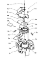
図3は、振れ補正ユニット3の分解斜視図である。図3において、31は固定部材であるところのベース板、36は補正レンズ12を保持する可動部材であるところの可動鏡筒、32a,32b,32cはベース板31と可動鏡筒36に狭持された球である。33a,33bはコイル、34a,34bは磁石、35a,35b,35cは弾性体、37は磁石吸着板、38a,38bは吸着板固定螺旋、39は可動鏡筒保持板、40はFPC(フレキシブルプリント基板)、41a,41bはFPC固定螺旋である。   FIG. 3 is an exploded perspective view of the shake correction unit 3. In FIG. 3, 31 is a base plate that is a fixed member, 36 is a movable barrel that is a movable member that holds the correction lens 12, and 32 a, 32 b, and 32 c are sandwiched between the base plate 31 and the movable barrel 36. Sphere. 33a and 33b are coils, 34a and 34b are magnets, 35a, 35b and 35c are elastic bodies, 37 is a magnet suction plate, 38a and 38b are suction plate fixing spirals, 39 is a movable lens barrel holding plate, and 40 is an FPC (flexible print). Substrate), 41a, 41b are FPC fixing spirals.

図3から明らかなように、本実施例1の振れ補正ユニット3は、ベース板31に対して片側に展開可能であり、組み付けが容易である。したがって、生産性が向上し、コストの低減が見込める。   As can be seen from FIG. 3, the shake correction unit 3 according to the first embodiment can be deployed on one side with respect to the base plate 31 and can be easily assembled. Therefore, productivity can be improved and cost reduction can be expected.

図4は、振れ補正ユニット3の詳細を示す図である。詳しくは、図4(a)は光軸方向からみた正面図、図4(b)は図4(a)のB−B断面での断面図、図4(c)は図4(a)のC−C断面での断面図である。   FIG. 4 is a diagram showing details of the shake correction unit 3. Specifically, FIG. 4A is a front view seen from the optical axis direction, FIG. 4B is a cross-sectional view taken along the line BB of FIG. 4A, and FIG. It is sectional drawing in CC cross section.

図4(a)に示したように、可動鏡筒36はベース板31に対して複数の弾性体35a,35b,35cで弾性支持されている。本実施例1では、弾性体35a,35b,35cが光軸中心から放射状に120度の間隔で3本配置されている。このような対称な配置とすることで、モーメントの発生による不要共振の励起を抑制することが可能となる。また、図4(b),(c)に示すように、弾性体35a,35b,35cは光軸方向に適宜傾けて取り付けられており、ベース板31と可動鏡筒36の間に設けられた球32a〜32cを把持している。   As shown in FIG. 4A, the movable lens barrel 36 is elastically supported by the plurality of elastic bodies 35 a, 35 b, and 35 c with respect to the base plate 31. In the first embodiment, three elastic bodies 35a, 35b, and 35c are arranged radially from the center of the optical axis at intervals of 120 degrees. By adopting such a symmetrical arrangement, it is possible to suppress excitation of unnecessary resonance due to generation of moment. Further, as shown in FIGS. 4B and 4C, the elastic bodies 35a, 35b, and 35c are attached so as to be appropriately inclined in the optical axis direction, and are provided between the base plate 31 and the movable lens barrel 36. The spheres 32a to 32c are held.

図3と図4(b)を用いてベース板31と可動鏡筒36の相対運動について説明する。ベース板31と可動鏡筒36は球32a〜32cを狭持しており、球32a〜32cを介して相対運動を行う。このため、転がり摩擦という非常に小さな摩擦の影響しか受けずに相対運動を行うことができる。摩擦が小さいために非常に小さな入力に対しても適切に応答することができる。また、球32a〜32cによる案内面を適切な精度で製作することにより、ベース板31と可動鏡筒36が相対運動を行った場合でも可動鏡筒36の傾きや光軸方向への不要な移動が発生することが無い。   The relative movement of the base plate 31 and the movable lens barrel 36 will be described with reference to FIGS. 3 and 4B. The base plate 31 and the movable lens barrel 36 hold the balls 32a to 32c, and perform relative motion via the balls 32a to 32c. For this reason, relative motion can be performed only under the influence of very small friction called rolling friction. Since the friction is small, it can respond appropriately even to a very small input. In addition, by manufacturing the guide surfaces by the balls 32a to 32c with appropriate accuracy, even when the base plate 31 and the movable lens barrel 36 move relative to each other, the movable lens barrel 36 is not required to tilt or move in the optical axis direction. Will not occur.

図4(c)および図5を用いて振れ補正ユニット3に具備されるアクチュエータについて説明する。図4(c)に示したように、ベース板31にはコイル33a,33bが固定され、可動鏡筒36には磁石34a,34bが固定されており、いわゆるムービングマグネット型のアクチュエータ、つまり駆動手段を構成している。   The actuator provided in the shake correction unit 3 will be described with reference to FIGS. As shown in FIG. 4C, coils 33a and 33b are fixed to the base plate 31, and magnets 34a and 34b are fixed to the movable lens barrel 36, so-called moving magnet type actuators, that is, driving means. Is configured.

図5はアクチュエータの模式図であり、図5(a)は磁石34aとコイル33aのみを光軸方向から見た図、図5(b)は磁石34aを中心付近で切断した時の断面図を示している。なお、磁石34bとコイル34bの相対的位置関係も同じである。   5A and 5B are schematic views of the actuator. FIG. 5A is a view of only the magnet 34a and the coil 33a viewed from the optical axis direction, and FIG. 5B is a cross-sectional view when the magnet 34a is cut near the center. Show. The relative positional relationship between the magnet 34b and the coil 34b is the same.

図5において、43は着磁境界である。また、図5(b)に示す42a,42b,42cは、磁石34a,34b、コイル33a,33b近傍の代表的な磁力線を模式的に表している。図5(a)に示したように、着磁境界43を挟んで磁石34aは2つの領域34a1,34a2に分けて着磁されている。着磁境界43はアクチュエータで発生する力の方向と直交する方向であり、図5(a)の上下方向に着磁境界が存在し、磁石34aおよび可動鏡筒36が左右方向に駆動される。コイル33aは光軸方向から見たときに小判型をしており、二つの長手部分33a1,33a2が磁石の二つの領域34a1,34a2と対向するように配置されている。   In FIG. 5, 43 is a magnetization boundary. Further, 42a, 42b, and 42c shown in FIG. 5B schematically represent typical magnetic lines of force near the magnets 34a and 34b and the coils 33a and 33b. As shown in FIG. 5A, the magnet 34a is magnetized in two regions 34a1 and 34a2 across the magnetization boundary 43. The magnetization boundary 43 is a direction orthogonal to the direction of the force generated by the actuator. There is a magnetization boundary in the vertical direction of FIG. 5A, and the magnet 34a and the movable lens barrel 36 are driven in the left-right direction. The coil 33a has an oval shape when viewed from the optical axis direction, and the two longitudinal portions 33a1 and 33a2 are arranged so as to face the two regions 34a1 and 34a2 of the magnet.

磁石34aのコイル33aと反対側の面には、図5(b)に示したように、ヨークを兼用する磁石吸着板37が配置される。磁石吸着板37は望ましくは軟磁性体であり、多くの磁束を透過させ、磁気回路のパーミアンス(漏れ易さ)を下げている。その結果、磁石34aからコイル33aに向かって比較的直線的に磁力線が生じている。磁石吸着板37は本実施例1では可動鏡筒36に固定されるので、厚みを増すと可動部の重量も増加してしまう。そこで、磁石吸着板37の外形、飽和磁束密度および磁石の形状、表面磁束密度などを考慮して、磁石吸着板37が飽和磁束近傍となるように決めるのが好ましい。この状態でコイル33aに通電すると、図5(b)の紙面垂直方向で33a1と33a2に反対方向に電流が流れる。フレミング左手の法則によって駆動力が発生する。図4(a)で説明したように、可動鏡筒36は弾性支持されているので、弾性体35a,35b,35cの合力と前記駆動力がつりあう位置までベース板31と可動鏡筒36の間に相対運動が生じる。   On the surface of the magnet 34a opposite to the coil 33a, a magnet attracting plate 37 that also serves as a yoke is disposed as shown in FIG. The magnet attracting plate 37 is preferably a soft magnetic material, and allows a large amount of magnetic flux to pass therethrough, thereby reducing the permeance (easy to leak) of the magnetic circuit. As a result, lines of magnetic force are generated relatively linearly from the magnet 34a toward the coil 33a. In the first embodiment, the magnet attracting plate 37 is fixed to the movable lens barrel 36. Therefore, when the thickness is increased, the weight of the movable portion is also increased. Therefore, it is preferable to determine the magnet attracting plate 37 to be in the vicinity of the saturated magnetic flux in consideration of the outer shape of the magnet attracting plate 37, the saturation magnetic flux density, the shape of the magnet, the surface magnetic flux density, and the like. When the coil 33a is energized in this state, a current flows in the opposite direction to 33a1 and 33a2 in the direction perpendicular to the paper surface of FIG. Driving force is generated by the Fleming's left hand rule. As described with reference to FIG. 4A, since the movable lens barrel 36 is elastically supported, the base plate 31 and the movable lens barrel 36 are moved to a position where the resultant force of the elastic bodies 35a, 35b, 35c and the driving force are balanced. Relative motion occurs.

次に、図6を用いて、適切な粘性抵抗を得るための減衰手段の取り付けについて説明する。図6(a)は振れ補正ユニット3を光軸方向からみた正面図、図6(b)は図6(a)のD−D断面での断面図、図6(c)は図6(b)の丸で囲った減衰手段取付部の詳細図である。   Next, the attachment of the damping means for obtaining an appropriate viscous resistance will be described with reference to FIG. 6A is a front view of the shake correction unit 3 viewed from the optical axis direction, FIG. 6B is a cross-sectional view taken along the line DD in FIG. 6A, and FIG. 6C is FIG. It is a detailed view of the damping means mounting portion surrounded by a circle.

図6において、44a,44bは減衰手段取付部、45は減衰手段、46は紫外線照射方向である。図6(b)に示すように、吸着板固定螺旋38a,38bは可動鏡筒36と螺旋締結された後、ベース板31に設けられた穴に向けて、少なくともベース板31と光軸方向にオーバーラップするように延在している。減衰手段取付部44a,44bは光軸対称に複数設けられることが望ましい。本実施例1では、図6(b)に示すように、光軸4に対して対称な位置に二つ設けられている。光軸4に対称に設けることで、ベース板31と可動鏡筒36が相対運動を行ったときに、減衰手段45から受ける力によって可動鏡筒36にモーメントが発生することが無い。   In FIG. 6, 44a and 44b are attenuation means attaching parts, 45 is attenuation means, and 46 is an ultraviolet irradiation direction. As shown in FIG. 6B, the suction plate fixing spirals 38 a and 38 b are spirally fastened to the movable lens barrel 36, and then toward the hole provided in the base plate 31 at least in the direction of the optical axis with the base plate 31. It extends to overlap. It is desirable that a plurality of attenuation means mounting portions 44a and 44b are provided symmetrically with respect to the optical axis. In the first embodiment, as shown in FIG. 6B, two are provided at positions symmetrical with respect to the optical axis 4. By providing symmetrically with respect to the optical axis 4, no moment is generated in the movable lens barrel 36 by the force received from the attenuation means 45 when the base plate 31 and the movable lens barrel 36 perform relative motion.

図6(c)は、減衰手段取付部44aの詳細図である。ベース板31に設けられた円筒形の穴31bに対して、可動鏡筒36に固定された吸着板固定螺旋38aがほぼ同心円状になるように配置され、その隙間にドーナツ状に減衰手段45が設けられている。減衰手段45は様々な粘弾性体を用いることが可能であるが、本実施例1では、組付け性や耐環境性に優れた紫外線硬化シリコーンゲルを用いている。ベース板31に設けられた穴31bは下方に開口しているので、矢印46方向から硬化前のゲルを塗布した後、紫外線を照射することで硬化させる。   FIG. 6C is a detailed view of the attenuation means attachment portion 44a. With respect to the cylindrical hole 31b provided in the base plate 31, the suction plate fixing spiral 38a fixed to the movable barrel 36 is arranged so as to be substantially concentric, and the damping means 45 is formed in a donut shape in the gap. Is provided. Although various viscoelastic bodies can be used for the attenuating means 45, in the first embodiment, an ultraviolet curable silicone gel excellent in assembling property and environmental resistance is used. Since the hole 31b provided in the base plate 31 opens downward, the gel before curing is applied from the direction of the arrow 46, and then cured by irradiating with ultraviolet rays.

図6に示すように、ベース板31上に設けられた突起31aと可動鏡筒36上に設けられた突起36aによって構成される機械的オーバーランの許容間隔をaとする。また、減衰手段45の、図6(c)に示す減衰手段45が設けられた個所の吸着板固定螺旋38aと穴31bの内壁の間隔をbとする。減衰手段45は大変形を起こさず、永久変形が起きない範囲(=弾性係数がリニアに変化する範囲)で使用されるのが好ましい。そのため、「a<b」を満たすように設けることが望ましい。永久変形を残さないためにはさらに「a<0.5b」の範囲であればより好適である。   As shown in FIG. 6, let a be the allowable interval of mechanical overrun constituted by the protrusion 31 a provided on the base plate 31 and the protrusion 36 a provided on the movable lens barrel 36. Further, the distance between the suction plate fixing spiral 38a and the inner wall of the hole 31b where the damping means 45 shown in FIG. It is preferable that the damping means 45 is used in a range in which no major deformation occurs and permanent deformation does not occur (= a range in which the elastic coefficient changes linearly). Therefore, it is desirable to provide so as to satisfy “a <b”. In order not to leave permanent deformation, it is more preferable that the range is “a <0.5b”.

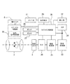
図7に、振れ補正ユニット3の制御系のブロック図を示す。51は振れセンサ8に相当するジャイロセンサ、52は低域通過フィルタ(以下、LPF)、53はアナログ/デジタルコンバータ(以下、A/D変換器)、54は図1のレンズシステム制御部30に相当するマイコンである。55は積分器、56は高域通過フィルタ(以下、HPF)、57は振れ信号処理部である。58は判定条件出力部であり、ユーザーの意図的なパンニング操作があった場合や三脚に固定された際に、振れ補正ユニット3がユーザーの意図に反した動きをしないように適切な判定条件を出力する。59は目標位置処理部、60は変換係数出力部、61はズーム情報、距離情報、レリーズ操作情報を出力する情報出力部である。62はフィルタ、63は追従制御部、64はオフセット・駆動感度などの情報出力部、65はデジタル/アナログコンバータ(以下、D/A変換器)である。66は振れ補正ユニット3に具備される上記したムービングマグネット型のアクチュエータ(駆動手段)に相当するドライバ部である。補正レンズ12の制御系は図7に示されるオープン制御系である。   FIG. 7 shows a block diagram of a control system of the shake correction unit 3. 51 is a gyro sensor corresponding to the shake sensor 8, 52 is a low-pass filter (hereinafter LPF), 53 is an analog / digital converter (hereinafter A / D converter), and 54 is in the lens system control unit 30 of FIG. It is an equivalent microcomputer. 55 denotes an integrator, 56 denotes a high-pass filter (hereinafter, HPF), and 57 denotes a shake signal processing unit. 58 is a determination condition output unit, which sets an appropriate determination condition so that the shake correction unit 3 does not move against the user's intention when the user performs an intentional panning operation or is fixed to a tripod. Output. 59 is a target position processing unit, 60 is a conversion coefficient output unit, 61 is an information output unit that outputs zoom information, distance information, and release operation information. Reference numeral 62 denotes a filter, 63 denotes a follow-up control unit, 64 denotes an information output unit such as an offset / driving sensitivity, and 65 denotes a digital / analog converter (hereinafter referred to as D / A converter). Reference numeral 66 denotes a driver unit corresponding to the moving magnet type actuator (driving means) provided in the shake correction unit 3. The control system of the correction lens 12 is an open control system shown in FIG.

像振れ補正を行う像振れ補正装置を備えた撮像装置1では、装置の大きさや精度などの制約から多くの場合、振れセンサ8としてジャイロセンサ51を用いている。図7に示した例では、ジャイロセンサ51の信号を適切なLPF52を介して高周波ノイズを除去した後、A/D変換器53を介してマイコン54に取り込む。   In many cases, the image pickup apparatus 1 including an image shake correction apparatus that performs image shake correction uses a gyro sensor 51 as the shake sensor 8 due to restrictions on the size and accuracy of the apparatus. In the example shown in FIG. 7, the signal from the gyro sensor 51 is taken into the microcomputer 54 via the A / D converter 53 after high frequency noise is removed via the appropriate LPF 52.

マイコン54内では、積分器55により積分を行うことで角速度信号を角度信号に変換する。そして、ジャイロセンサ51のドリフトなどの影響を低減するために適切な時定数のHPF56を用いる。振れ信号処理部57では、得られた角度信号から、判定条件出力部58からの振れ補正ユニット3がユーザーの意図に反した動きをしないように適切な判定条件のもと、制御すべき信号を抽出する。   In the microcomputer 54, the angular velocity signal is converted into an angle signal by integration by the integrator 55. An HPF 56 having an appropriate time constant is used to reduce the influence of drift of the gyro sensor 51 and the like. In the shake signal processing unit 57, a signal to be controlled is determined from an obtained angle signal under an appropriate determination condition so that the shake correction unit 3 from the determination condition output unit 58 does not move against the user's intention. Extract.

目標位置処理部59では、情報出力部61および変換係数出力部60の出力を基に、つまりズーム情報、フォーカス情報61などを基に、さらには予め定められた変換係数を基に、角度信号を補正レンズ12の変位信号などに変換する。フィルタ62としては、振れ補正ユニット3、ジャイロセンサ51などの周波数特性を勘案してシステム全体として手振れを適切に抑制できるような周波数特性をもつものが用いられる。このフィルタ62の詳細は後述する。追従制御部63では、振れ補正ユニット3の駆動感度やオフセットなどの情報出力部64からの情報を基に、フィルタ62の出力を振れ補正ユニット3の制御信号に変換する。   The target position processing unit 59 outputs the angle signal based on the outputs of the information output unit 61 and the conversion coefficient output unit 60, that is, based on the zoom information, the focus information 61, etc., and further based on the predetermined conversion coefficient. This is converted into a displacement signal of the correction lens 12 or the like. As the filter 62, a filter having frequency characteristics that can appropriately suppress camera shake as the entire system in consideration of the frequency characteristics of the shake correction unit 3, the gyro sensor 51, and the like is used. Details of the filter 62 will be described later. The follow-up control unit 63 converts the output of the filter 62 into a control signal for the shake correction unit 3 based on information from the information output unit 64 such as drive sensitivity and offset of the shake correction unit 3.

これらマイコン54内で処理を終えた信号はD/A変換器65を介してドライバ部66へ出力され、振れ補正ユニット3が駆動される。つまり、補正レンズ12を保持する可動鏡筒36が固定部材であるベース板31に対して相対的に位置変化(光軸と直交する平面内で移動)し、手振れ等による像振れの補正が行われる。   The signals that have been processed in the microcomputer 54 are output to the driver unit 66 via the D / A converter 65, and the shake correction unit 3 is driven. That is, the movable lens barrel 36 that holds the correction lens 12 changes its position relative to the base plate 31 that is a fixed member (moves in a plane orthogonal to the optical axis), and image blur due to camera shake or the like is corrected. Is called.

上述した各部の係数を適切に設定することで、手振れが生じた場合でも撮像素子6上における被写体像の振れが軽減される。   By appropriately setting the coefficients of the above-described units, the shake of the subject image on the image sensor 6 can be reduced even when hand shake occurs.

図8に、図7を簡略化して主要部のみモデル化したブロック図を示す。図8の入力は、図7の目標位置処理部59を通って出力された目標レンズ位置であり、出力はフィルタ62、追従制御部63を介して出力された実際の補正レンズ12の位置である。   FIG. 8 shows a block diagram in which only the main part is modeled by simplifying FIG. The input in FIG. 8 is the target lens position output through the target position processing unit 59 in FIG. 7, and the output is the actual position of the correction lens 12 output through the filter 62 and the tracking control unit 63. .

以下の説明を簡単にするために、フィルタ62の周波数特性(伝達関数)をF(s)、振れ補正ユニット3の周波数特性(伝達関数)をG(s),ドライバゲインおよび駆動感度調整のゲインをKとする。なお、F(s)およびG(s)のsはラプラス演算子である。   In order to simplify the following description, the frequency characteristic (transfer function) of the filter 62 is F (s), the frequency characteristic (transfer function) of the shake correction unit 3 is G (s), the driver gain, and the gain for adjusting the drive sensitivity. Is K. Note that s in F (s) and G (s) is a Laplace operator.

ここで、手振れの性能を示す指標として抑振率を定義する。抑振率は、入力と出力の差を入力で正規化した値のノルムとして定義する。入力をX(s)とするとき、図8から明らかに、以下の数1のようになる。   Here, a vibration suppression rate is defined as an index indicating the performance of camera shake. The suppression rate is defined as the norm of the value obtained by normalizing the difference between input and output. Assuming that the input is X (s), it is apparent from FIG.

Figure 2008292902
定義から明らかなように、上記の抑振率は小さいほど、高い像振れ抑制性能を示す。
Figure 2008292902
As is clear from the definition, the smaller the above-described suppression rate, the higher the image blur suppression performance.

次に、図9〜図11を用いて、本実施例1の要部であるフィルタ62の周波数特性F(s)および振れ補正ユニット3の周波数特性G(s)について説明する。   Next, the frequency characteristic F (s) of the filter 62 and the frequency characteristic G (s) of the shake correction unit 3 which are the main parts of the first embodiment will be described with reference to FIGS.

図9(a),(b)は、図3ないし図6で説明した振れ補正ユニット3の周波数特性G(s)である。振れ補正ユニット3、詳しくは補正レンズ12を2軸方向に駆動可能だが、図9に示した特性は、そのうちの1軸方向について、減衰手段45が有る場合と無い場合をボード線図で表現している。振れ補正ユニット3の要部は線対称の構造をしているので、図9に示さないもう1軸の特性も類似した特性になる。以下では説明を簡単にするために1軸方向に限って説明を行う。また、図9において、ボード線図のゲインは十分低い周波数でのゲインが1になるように正規化して表現している。   FIGS. 9A and 9B are frequency characteristics G (s) of the shake correction unit 3 described with reference to FIGS. Although the shake correction unit 3, specifically, the correction lens 12 can be driven in two axial directions, the characteristics shown in FIG. 9 are expressed in a Bode diagram with and without the attenuation means 45 in one axial direction. ing. Since the main part of the shake correction unit 3 has a line-symmetric structure, the characteristics of the other axis not shown in FIG. 9 have similar characteristics. In the following, in order to simplify the description, the description is limited to only one axis direction. In FIG. 9, the Bode diagram gain is normalized and expressed so that the gain at a sufficiently low frequency is 1.

図9の例では、30Hz強の位置に主共振があり、45Hz付近に副共振がある。副共振は、図3ないし図6に示した可動鏡筒36が光軸周りに回転するいわゆるローリングが起こることによって発生する。本実施例1では、減衰手段45を適切に介在させることで、主共振および副共振の影響を低減している。これにより、撮像装置1のシャッタの動作などにより不要な共振が励起されることが無い。   In the example of FIG. 9, there is a main resonance at a position of slightly above 30 Hz, and a sub-resonance near 45 Hz. The sub-resonance is generated by so-called rolling that the movable lens barrel 36 shown in FIGS. 3 to 6 rotates around the optical axis. In the first embodiment, the influence of the main resonance and the sub-resonance is reduced by appropriately interposing the attenuation means 45. Thereby, unnecessary resonance is not excited by the operation of the shutter of the imaging apparatus 1 or the like.

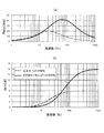
図10(a),(b)に、本実施例1に係わるフィルタ62および従来のフィルタの周波数特性を示す。図9に示したように、振れ補正ユニット3の周波数特性はいわゆる2次遅れ系になるので、共振周波数に近づくにつれて位相が遅れ、最終的に180度位相が反転する。この影響を低減して、上記数1に示した抑振率を低減するために従来から位相進みフィルタが用いられてきた。   FIGS. 10A and 10B show frequency characteristics of the filter 62 according to the first embodiment and the conventional filter. As shown in FIG. 9, since the frequency characteristic of the shake correction unit 3 is a so-called second-order lag system, the phase is delayed as the resonance frequency is approached, and the phase is finally inverted by 180 degrees. Conventionally, a phase advance filter has been used in order to reduce this influence and reduce the suppression rate shown in Equation 1 above.

図10に示した従来のフィルタはその一例である。位相進みフィルタでは、低域に比べて高域のゲインが持ち上がる。しかし、従来のフィルタでは、高域にある副共振などの不要な機械的共振の影響を無くすために大きくゲインが持ち上がるフィルタは適当ではなかった。このような制約のもとでフィルタによる抑振率の改善効果を得るためには、位相補償のピークが共振周波数付近または共振周波数よりも若干低い周波数になるような位相進みフィルタが用いられてきた。   The conventional filter shown in FIG. 10 is an example. In the phase advance filter, the gain in the high band is raised compared to the low band. However, in the conventional filter, a filter that greatly increases the gain in order to eliminate the influence of unnecessary mechanical resonance such as sub-resonance in the high band is not appropriate. In order to obtain the improvement effect of the suppression rate by the filter under such constraints, a phase advance filter has been used in which the peak of phase compensation is near the resonance frequency or slightly lower than the resonance frequency. .

これに対し、本実施例1では、減衰手段45が設けられているために副共振などの不要な機械的共振の影響を無視できる。そのため、従来よりも積極的なフィルタを用いることができる。具体的には、図10に示すような、共振周波数よりも高い周波数に位相補償のピーク(最大値)を持つような1次の位相進みフィルタが好適な例である。1次の位相進みフィルタを用いたのは、演算が簡易で、より安価なマイコンを用いた場合にも、適切な制御が行えるためである。位相補償量(図10(a)のPhase)の“すそ野”部分を有効に活用することで、広い範囲で適切な位相補償を行うことが可能となる。   On the other hand, in the first embodiment, since the attenuation means 45 is provided, the influence of unnecessary mechanical resonance such as sub-resonance can be ignored. Therefore, a more aggressive filter can be used than before. Specifically, a first-order phase lead filter having a phase compensation peak (maximum value) at a frequency higher than the resonance frequency as shown in FIG. 10 is a suitable example. The reason why the primary phase advance filter is used is that the calculation is simple and appropriate control can be performed even when a cheaper microcomputer is used. By effectively utilizing the “side” portion of the phase compensation amount (Phase in FIG. 10A), it is possible to perform appropriate phase compensation over a wide range.

図11に、本実施例1に係わるフィルタ62を用いた場合、従来のフィルタを用いた場合、およびフィルタが無い場合、の抑振率を示す。本実施例1に係わるフィルタ62を用いることで、広い周波数領域で抑振率を改善できていることが分かる。   FIG. 11 shows the suppression rate when the filter 62 according to the first embodiment is used, when the conventional filter is used, and when there is no filter. It can be seen that by using the filter 62 according to the first embodiment, the suppression rate can be improved in a wide frequency range.

上記の実施例1によれば、弾性体35a〜35cと可動鏡筒36で決まる共振周波数よりも高い周波数に位相補償の最大値をもつような、位相補償手段であるフィルタ62を、演算手段であるマイコン54に具備する構成にしている。詳しくは、1次の位相進み補償を行うフィルタ62を具備するようにしている。   According to the first embodiment, the filter 62 that is the phase compensation means having the maximum value of phase compensation at a frequency higher than the resonance frequency determined by the elastic bodies 35a to 35c and the movable lens barrel 36 is obtained by the computing means. A configuration is provided in a certain microcomputer 54. Specifically, a filter 62 that performs first-order phase lead compensation is provided.

以上のようなフィルタ62をマイコン54に具備することで、簡単なフィルタ構成で、広い帯域で高い像振れ補正性能を得ることが可能となる。   By providing the filter 62 as described above in the microcomputer 54, it is possible to obtain high image blur correction performance in a wide band with a simple filter configuration.

図12ないし図22を用いて、本発明の実施例2に係わる像振れ補正装置を具備する撮像装置について説明する。なお、撮像装置の構成は、上記実施例1に示した図1及び図2の構成と同様であるので、説明は省略する。   With reference to FIGS. 12 to 22, an image pickup apparatus including an image shake correction apparatus according to the second embodiment of the present invention will be described. The configuration of the imaging apparatus is the same as that shown in FIGS. 1 and 2 described in the first embodiment, and a description thereof will be omitted.

図12ないし図22を用いて、本実施例2の要部である、像振れ補正のための振れ補正ユニット300について説明する。図12は本実施例2に係わる振れ補正ユニット300の分解斜視図であり、実施例1の振れ補正ユニット3と同じ機能を持つものに関しては同じ符号を付している。   A shake correction unit 300 for image shake correction, which is a main part of the second embodiment, will be described with reference to FIGS. FIG. 12 is an exploded perspective view of the shake correction unit 300 according to the second embodiment. Components having the same functions as those of the shake correction unit 3 according to the first embodiment are denoted by the same reference numerals.

図12において、101はヨークを兼ねる磁石吸着板で、実施例1の磁石吸着板と異なり、適切な穴が設けられている。図12から明らかなように、本実施例2の機構はベース板31に対して片側に展開可能であり、組み付けが容易である。したがって、生産性が向上し、コストの低減が見込める。   In FIG. 12, reference numeral 101 denotes a magnet suction plate that also serves as a yoke. Unlike the magnet suction plate of the first embodiment, an appropriate hole is provided. As is clear from FIG. 12, the mechanism of the second embodiment can be deployed on one side with respect to the base plate 31 and can be easily assembled. Therefore, productivity can be improved and cost reduction can be expected.

図13は振れ補正ユニット300の平面図である。詳しくは、図13(a)は光軸方向からみた正面図、図13(b)は図13(a)のB−B断面図、図13(c)は図13(a)のC−C断面図、図13(d)は図13(c)の丸で囲った部分の詳細図である。   FIG. 13 is a plan view of the shake correction unit 300. Specifically, FIG. 13A is a front view seen from the optical axis direction, FIG. 13B is a cross-sectional view taken along line BB in FIG. 13A, and FIG. 13C is a cross-sectional view taken along line CC in FIG. A sectional view, FIG. 13 (d) is a detailed view of a circled portion of FIG. 13 (c).

図13に示したように、可動部の支持方法は実施例1と同じ方法を取っている。つまり、可動鏡筒36はベース板31に対して複数の弾性体35a〜35cで弾性支持されている。本実施例2では、弾性体35a〜35cが光軸4から放射状に120度の間隔で3本配置されている。このような対称な配置とすることで、モーメントの発生による不要共振の励起を抑制することが可能となる。また、弾性体35a〜35cは光軸方向に適宜傾けて取り付けられており、ベース板31と可動鏡筒36の間に設けられた球32a,32b,32c(図12も参照)を把持している。   As shown in FIG. 13, the movable part is supported by the same method as in the first embodiment. That is, the movable lens barrel 36 is elastically supported by the plurality of elastic bodies 35 a to 35 c with respect to the base plate 31. In the second embodiment, three elastic bodies 35a to 35c are arranged radially from the optical axis 4 at intervals of 120 degrees. By adopting such a symmetrical arrangement, it is possible to suppress excitation of unnecessary resonance due to generation of moment. In addition, the elastic bodies 35a to 35c are attached so as to be appropriately inclined in the optical axis direction, and hold the balls 32a, 32b, 32c (see also FIG. 12) provided between the base plate 31 and the movable lens barrel 36. Yes.

振れ補正ユニット300の可動部の案内面の構成は、実施例1の図4(b)に示したものと同じ構造である。   The configuration of the guide surface of the movable part of the shake correction unit 300 is the same as that shown in FIG.

図13(b)、図14及び図15を用いて、振れ補正ユニット300のアクチュエータ、つまり駆動手段について説明する。アクチュエータは、実施例1の図4(c)に示した構造とほぼ同一構造であり、アクチュエータの一部を構成しているコイル33a,33bに通電することによってベース板31と可動鏡筒36の間に相対運動が生じる。違いは、磁石34a,34bに対してコイル33a,33bの反対側にセンサ102が設けられている。本実施例2は、いわゆるムービングマグネット型のアクチュエータのため、センサ102としてホール素子を用いている。センサ102はベース板31にFPC40を介して固定されており、可動鏡筒36の位置を磁束密度の変化によって検出する。また、センサ102であるホール素子を前述の配置とすることで、駆動用の磁石34a,34bを位置検出用の磁石として兼用している。   The actuator, that is, the driving unit of the shake correction unit 300 will be described with reference to FIGS. 13B, 14, and 15. The actuator has substantially the same structure as that shown in FIG. 4C of the first embodiment, and the base plate 31 and the movable lens barrel 36 are energized by energizing the coils 33a and 33b constituting a part of the actuator. Relative motion occurs between them. The difference is that the sensor 102 is provided on the opposite side of the coils 33a and 33b with respect to the magnets 34a and 34b. Since the second embodiment is a so-called moving magnet type actuator, a Hall element is used as the sensor 102. The sensor 102 is fixed to the base plate 31 via the FPC 40, and detects the position of the movable lens barrel 36 by a change in magnetic flux density. Further, by arranging the Hall element as the sensor 102 as described above, the driving magnets 34a and 34b are also used as position detecting magnets.

図14はアクチュエータの模式図であり、図14(a)は磁石、コイルおよびセンサを光軸方向から見た図、図14(b)は磁石を中心付近で切断した時の断面図を示している。   14A and 14B are schematic views of an actuator. FIG. 14A is a view of a magnet, a coil, and a sensor viewed from the optical axis direction, and FIG. 14B is a cross-sectional view when the magnet is cut near the center. Yes.

図14において、110はセンサ102の感磁部である。図14に示した磁気回路では、磁束42a,42b,42cは図示した矢印のような流れをしている。図14(b)の状態では、感磁部110は着磁境界43の真上に位置しているので、この点の磁界はほぼ0に等しくなる。ベース板31と可動鏡筒36の間に相対運動が生じた場合、ベース板31に固定されたセンサ102から見みて、着磁境界43は可動鏡筒36と一緒に動くので、感磁部110の磁界は0ではない値を示す。   In FIG. 14, reference numeral 110 denotes a magnetic sensitive part of the sensor 102. In the magnetic circuit shown in FIG. 14, the magnetic fluxes 42a, 42b, and 42c flow as shown by the arrows. In the state of FIG. 14B, since the magnetic sensing part 110 is located immediately above the magnetization boundary 43, the magnetic field at this point is substantially equal to zero. When relative movement occurs between the base plate 31 and the movable lens barrel 36, the magnetizing boundary 43 moves together with the movable lens barrel 36 as viewed from the sensor 102 fixed to the base plate 31. Indicates a non-zero value.

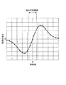
この様子を実験的に取得したものを、図15に示している。図15において、移動量0とは、図14(b)に示した、感磁部110が着磁境界43の真上に位置した状態をいう。図15から分かるように、一定の範囲では、移動量と磁界の強さは線形関係が保たれており、この範囲では線形関係により位置を検出可能である。   FIG. 15 shows a result obtained experimentally. In FIG. 15, the amount of movement 0 means a state in which the magnetic sensing part 110 is located immediately above the magnetization boundary 43 shown in FIG. As can be seen from FIG. 15, in a certain range, the movement amount and the magnetic field strength have a linear relationship, and in this range, the position can be detected by the linear relationship.

次に、図13(c),(d)を用いて、減衰手段104の取り付けについて説明する。図13(c),(d)において、103a,103bは減衰手段取付部を、104は減衰手段を、105aは紫外線透過板を、106は紫外線照射方向を、それぞれ示している。図13(c)に示すように、減衰手段取付部103a,103bは、実施例1と同じく光軸4に対称に二つ設けられている。吸着板固定螺旋38a,38bは可動鏡筒36と螺旋締結された後、ベース板31に設けられた穴31bに向けて、少なくともベース板31と光軸方向にオーバーラップし、且つ貫通しないように延在している。紫外線透過板105aをベース板31に取り付けた後に、減衰手段104を注入した後可動鏡筒36を組み込む。最後に、106方向から紫外線を照射することで、減衰手段104を硬化させることができる。減衰手段104として用いる粘弾性体は、実施例1に示したものとする。   Next, attachment of the damping means 104 will be described with reference to FIGS. 13 (c) and 13 (d). 13C and 13D, reference numerals 103a and 103b denote attenuating means mounting portions, 104 denotes an attenuating means, 105a denotes an ultraviolet transmitting plate, and 106 denotes an ultraviolet irradiation direction. As shown in FIG. 13C, two attenuation means attaching portions 103a and 103b are provided symmetrically with respect to the optical axis 4 as in the first embodiment. After the suction plate fixing spirals 38a and 38b are spirally fastened to the movable lens barrel 36, the suction plate fixing spirals 38a and 38b overlap at least the base plate 31 in the optical axis direction and do not penetrate through the holes 31b provided in the base plate 31. It is extended. After the ultraviolet transmissive plate 105a is attached to the base plate 31, the attenuating means 104 is injected, and then the movable lens barrel 36 is incorporated. Finally, the attenuation means 104 can be cured by irradiating ultraviolet rays from the direction 106. The viscoelastic body used as the attenuating means 104 is assumed to be that shown in the first embodiment.

図16に、振れ補正ユニット300の制御系のブロック図を示す。実施例1における図7と同じ機能を有する部分は同一符号を付し、その詳細は省略する。図16において、300は振れ補正ユニット、67は補正レンズ12の位置を検出する位置検出センサ(図14のセンサ102に相当)、68はA/D変換器である。補正レンズ12の制御系は、図16に示されるようにフィードバック制御系である。   FIG. 16 shows a block diagram of a control system of the shake correction unit 300. The parts having the same functions as those in FIG. 16, 300 is a shake correction unit, 67 is a position detection sensor (corresponding to the sensor 102 in FIG. 14) for detecting the position of the correction lens 12, and 68 is an A / D converter. The control system of the correction lens 12 is a feedback control system as shown in FIG.

図16に示した実施例2においても、目標位置処理部59の出力までの信号処理は、上記の実施例1の場合と同様になされる。しかし、本実施例2では、いわゆるフィードバック系を構成しており、振れ補正ユニット300の変位をホール素子などの適切な位置検出センサ67でモニターする。そして、この位置検出信号をA/D変換器68を介してマイコン54に取り込み、フィルタ62により適切な処理をして追従制御部63にフィードバックするようにしている。フィードバック系のサンプリング周波数は制御帯域を考えて適切に設定される。一般的に手振れ補正のための制御系では、制御すべき周波数が100Hz程度までのため、数kHz程度のサンプリング周波数があればよい。   Also in the second embodiment shown in FIG. 16, the signal processing up to the output of the target position processing unit 59 is performed in the same manner as in the first embodiment. However, in the second embodiment, a so-called feedback system is configured, and the displacement of the shake correction unit 300 is monitored by an appropriate position detection sensor 67 such as a Hall element. Then, this position detection signal is taken into the microcomputer 54 via the A / D converter 68, subjected to appropriate processing by the filter 62, and fed back to the follow-up control unit 63. The sampling frequency of the feedback system is appropriately set in consideration of the control band. In general, a control system for correcting camera shake requires a sampling frequency of about several kHz because the frequency to be controlled is up to about 100 Hz.

図17に、図16を簡略化して主要部のみモデル化したブロック図を示す。図17の入力は、図16の目標位置処理部59を通って出力された目標レンズ位置であり、出力はフィルタ62、追従制御部63、振れ補正ユニット300を介して出力された実際の補正レンズ12の位置である。以下の説明を簡単にするために、フィルタの周波数特性(伝達関数)をF(s),振れ補正ユニット300の周波数特性(伝達関数)をG(s),ドライバゲインおよび駆動感度調整のゲインをK、位置検出センサ67のゲインをK’とする。   FIG. 17 shows a block diagram in which only the main part is modeled by simplifying FIG. The input in FIG. 17 is the target lens position output through the target position processing unit 59 in FIG. 16, and the output is the actual correction lens output through the filter 62, the tracking control unit 63, and the shake correction unit 300. 12 positions. In order to simplify the following explanation, the frequency characteristic (transfer function) of the filter is F (s), the frequency characteristic (transfer function) of the shake correction unit 300 is G (s), and the driver gain and the gain for adjusting the drive sensitivity are set. K, and the gain of the position detection sensor 67 is K ′.

ここで、図17の閉ループ系の伝達関数を考えると、明らかに以下の数2である。   Here, when considering the transfer function of the closed loop system of FIG.

Figure 2008292902
実施例1で定義した抑振率は、以下の数3となる。
Figure 2008292902
The vibration suppression rate defined in the first embodiment is expressed by the following formula 3.

Figure 2008292902
数3の抑振率を小さくするためには、G’(S)を広い帯域で1に近づければよく、これはフィードバック制御では交叉周波数を高く設定できれば実現可能となる。
Figure 2008292902
In order to reduce the suppression rate of Equation 3, G ′ (S) may be brought close to 1 in a wide band, and this can be realized in feedback control if the crossover frequency can be set high.

図18〜図22を用いて、本実施例2の要部であるフィルタ62の周波数特性F(s)および振れ補正ユニット300の周波数特性G(s)について説明する。   The frequency characteristic F (s) of the filter 62 and the frequency characteristic G (s) of the shake correction unit 300, which are the main parts of the second embodiment, will be described with reference to FIGS.

図18(a),(b)は、図12〜図15で説明した本実施例2に係わる振れ補正ユニット300の周波数特性G(s)である。振れ補正ユニット300は2軸方向に駆動可能だが、図18に示した特性はそのうちの1軸方向について、減衰手段45が無い場合をボード線図で表現している。本実施例2に示した機構は、振れ補正ユニット300の要部は線対称の構造をしているので、図18に示さないもう1軸の特性も類似した特性になる。以下では説明を簡単にするために1軸方向に限って説明を行う。また、図18において、ボード線図のゲインは十分低い周波数でのゲインが1になるように正規化して表現している。   18A and 18B are frequency characteristics G (s) of the shake correction unit 300 according to the second embodiment described with reference to FIGS. Although the shake correction unit 300 can be driven in two axial directions, the characteristics shown in FIG. 18 represent the case where the attenuation means 45 is not provided in one axial direction in a Bode diagram. In the mechanism shown in the second embodiment, since the main part of the shake correction unit 300 has a line-symmetric structure, the characteristics of the other axis not shown in FIG. 18 have similar characteristics. In the following, in order to simplify the description, the description is limited to only one axis direction. In FIG. 18, the Bode diagram gain is normalized and expressed so that the gain at a sufficiently low frequency is 1.

図18の例では、30Hz強の位置に主共振があり、300Hz付近に副共振がある。副共振は、図12〜図15に示した機構の可動鏡筒38が光軸周りに回転するいわゆるローリング光軸に垂直な平面に対して傾くピッチング等が起こることによって発生する。   In the example of FIG. 18, there is a main resonance at a position of slightly above 30 Hz, and a sub-resonance near 300 Hz. The sub-resonance is generated by the occurrence of pitching that is inclined with respect to a plane perpendicular to the rolling optical axis in which the movable lens barrel 38 of the mechanism shown in FIGS. 12 to 15 rotates around the optical axis.

図19(a),(b)に、本実施例2に係わるフィルタ62および従来のフィルタの周波数特性を示す。図18に示したように、振れ補正ユニット300の周波数特性はいわゆる2次遅れ系になるので、共振周波数に近づくにつれて位相が遅れ、最終的に180度位相が反転する。この影響を低減して、数3に示した抑振率を低減するために従来から位相進みフィルタが用いられてきた。図19に示した従来のフィルタはその一例である。位相進みフィルタでは、低域に比べて高域のゲインが持ち上がる。   FIGS. 19A and 19B show frequency characteristics of the filter 62 according to the second embodiment and the conventional filter. As shown in FIG. 18, since the frequency characteristic of the shake correction unit 300 is a so-called second-order lag system, the phase is delayed as the resonance frequency is approached, and the phase is finally inverted by 180 degrees. Conventionally, a phase advance filter has been used in order to reduce this influence and reduce the suppression rate shown in Equation (3). The conventional filter shown in FIG. 19 is an example. In the phase advance filter, the gain in the high band is raised compared to the low band.

図18(a),(b)を用いて、フィードバック系のサーボ設計について説明する。従来の様に減衰手段を備えていない振れ補正ユニットでは、位相余裕およびゲイン余裕を考えてサーボ設計をする必要がある。例えば、図18に示す従来のフィルタでは、図18の状態に対して5dB程度のゲインアップを行った場合、交叉周波数は65Hz付近で、位相余裕が30deg程度、300Hz付近のゲイン余裕が8dB程度保たれ、サーボ系は安定に保たれる。   The feedback servo design will be described with reference to FIGS. 18 (a) and 18 (b). In a shake correction unit that does not include attenuation means as in the prior art, it is necessary to design the servo in consideration of the phase margin and gain margin. For example, in the conventional filter shown in FIG. 18, when a gain increase of about 5 dB is performed with respect to the state of FIG. 18, the crossover frequency is around 65 Hz, the phase margin is about 30 deg, and the gain margin around 300 Hz is kept about 8 dB. As a result, the servo system is kept stable.

一方、本実施例2に係わるフィルタ62でも、5dB程度のゲインアップを行った場合、交叉周波数は80Hz付近で、位相余裕は45deg程度と十分であるが、300Hz付近のゲイン余裕が2dB程度となり、サーボ系が安定しない。そのため、十分に閉ループゲインを上げることができず、結果として抑振率を高めることができない。サーボ系が不安定とならない範囲でサーボ設計したときの抑振率の一例を、図20に示す。本実施例2に係わるフィルタのみでは、従来のフィルタに対しても有意に制御帯域を改善することができない。上述したように、適切な減衰手段45が介在しない振れ補正ユニットでは、本実施例2に係わるフィルタ62のみでは必ずしも適切なものではなかった。   On the other hand, in the filter 62 according to the second embodiment, when a gain increase of about 5 dB is performed, the crossover frequency is about 80 Hz and the phase margin is about 45 degrees, but the gain margin near 300 Hz is about 2 dB. Servo system is not stable. Therefore, the closed loop gain cannot be sufficiently increased, and as a result, the vibration suppression rate cannot be increased. FIG. 20 shows an example of the damping rate when the servo is designed within a range where the servo system does not become unstable. With only the filter according to the second embodiment, the control band cannot be improved significantly over the conventional filter. As described above, in the shake correction unit in which the appropriate attenuation means 45 is not interposed, the filter 62 according to the second embodiment alone is not necessarily appropriate.

これに対し、本実施例2では、減衰手段45が設けられているために副共振などの不要な機械的共振の影響を低減できるので、従来よりも積極的なフィルタを用いることができる。具体的には、図19に示すような、共振周波数よりも高い周波数に位相補償のピークを持つような1次の位相進みフィルタが好適な例である。1次の位相進みフィルタを用いたのは、演算が簡易でより安価なマイコンを用いた場合にも適切な制御が行えるためである。位相補償量(図19(a)のPhase)の“すそ野”部分を有効に活用することで広い範囲で適切な位相補償を行うことが可能となる。   On the other hand, in the second embodiment, since the attenuation means 45 is provided, the influence of unnecessary mechanical resonance such as sub-resonance can be reduced, so that a more aggressive filter than before can be used. Specifically, a first-order phase lead filter having a phase compensation peak at a frequency higher than the resonance frequency as shown in FIG. 19 is a suitable example. The reason why the first-order phase advance filter is used is that appropriate control can be performed even when a simpler and cheaper microcomputer is used. By effectively utilizing the “side” portion of the phase compensation amount (Phase in FIG. 19A), it is possible to perform appropriate phase compensation over a wide range.

図21に、減衰手段45が有る場合の振れ補正ユニットの周波数特性G(s)を示す。   FIG. 21 shows the frequency characteristic G (s) of the shake correction unit when the attenuation means 45 is provided.

図18に示した特性と減衰手段45を介在させたことを除いては同一の機構であるが、300Hz付近の不要共振峰が十分に抑えられている。図21の周波数特性であれば、従来のフィルタよりも交叉周波数を上げることが可能となる。具体的には、従来のフィルタでは位相余裕から交叉周波数を70Hz程度にするのが安定の限界であるが、本実施例2に係わるフィルタ62は、交叉周波数を120Hz程度にしても位相余裕、ゲイン余裕共に問題ない。その結果、本実施例2に係わるフィルタ62では、より広い帯域で、高い抑振率が得られる。サーボ系が不安定とならない範囲でサーボ設計したときの抑振率の一例を、図22に示す。   Although the mechanism is the same as that shown in FIG. 18 except that the attenuation means 45 is interposed, unnecessary resonance peaks in the vicinity of 300 Hz are sufficiently suppressed. With the frequency characteristics shown in FIG. 21, the crossover frequency can be increased as compared with the conventional filter. Specifically, in the conventional filter, the limit of stability is that the crossover frequency is about 70 Hz from the phase margin, but the filter 62 according to the second embodiment has a phase margin and gain even if the crossover frequency is about 120 Hz. There is no problem with both margins. As a result, the filter 62 according to the second embodiment can obtain a high suppression rate in a wider band. FIG. 22 shows an example of the vibration suppression rate when the servo is designed within a range where the servo system does not become unstable.

上記の実施例2によれば、弾性体35a〜35cと可動鏡筒36で決まる共振周波数よりも高い周波数に位相補償の最大値をもつような、位相補償手段であるフィルタ62を、演算手段であるマイコン54に具備する構成にしている。詳しくは、1次の位相進み補償を行うフィルタ62をフィードバック制御系内に具備するようにしている。   According to the second embodiment, the filter 62, which is a phase compensation means having a maximum value of phase compensation at a frequency higher than the resonance frequency determined by the elastic bodies 35a to 35c and the movable lens barrel 36, is calculated by the computing means. A configuration is provided in a certain microcomputer 54. Specifically, a filter 62 that performs first-order phase lead compensation is provided in the feedback control system.

以上に示したようなフィルタ62を用いることで、簡単なフィルタ構成で、広い帯域で高い手振れ補正性能を得ることが可能となる。   By using the filter 62 as described above, it is possible to obtain high camera shake correction performance in a wide band with a simple filter configuration.

(本発明と実施例の対応)
補正レンズ12が本発明の像振れ補正用の補正手段に、可動鏡筒36が本発明の保持部材に、ベース板31が、保持部材を光軸に直交する平面内で移動可能に支持する固定部材に、それぞれ相当する。また、弾性体35a〜35cが、可動部材を固定部材に対して弾性的に支持する弾性手段に、コイル33a,33bおよび磁石34a,34bが、保持部材の固定部材に対する相対的な位置を変化させる駆動手段に相当する。また、減衰手段45,104が、保持部材と固定部材の間に配置される減衰手段に、振れセンサ8、ジャイロセンサ51が本発明の振れ検出手段に、CPU54が、振れ検出手段からの信号を処理して駆動手段に出力する演算手段に、それぞれ相当する。また、フィルタ62が、弾性部材と可動部材で決まる共振周波数よりも高い周波数に位相補償の最大値をもつような位相補償手段に相当する。
(Correspondence between the present invention and the embodiment)
The correction lens 12 is a correction means for correcting image blur of the present invention, the movable lens barrel 36 is fixed to the holding member of the present invention, and the base plate 31 is fixed to support the holding member so as to be movable in a plane perpendicular to the optical axis. It corresponds to each member. Further, the elastic bodies 35a to 35c are elastic means for elastically supporting the movable member with respect to the fixed member, and the coils 33a and 33b and the magnets 34a and 34b change the relative position of the holding member with respect to the fixed member. It corresponds to the driving means. Further, the damping means 45 and 104 are the damping means disposed between the holding member and the fixing member, the shake sensor 8 and the gyro sensor 51 are the shake detection means of the present invention, and the CPU 54 receives the signal from the shake detection means. It corresponds to the calculation means which processes and outputs to a drive means, respectively. Further, the filter 62 corresponds to a phase compensation means having a maximum value of phase compensation at a frequency higher than the resonance frequency determined by the elastic member and the movable member.

本発明は、補正レンズ12による像振れ補正装置に限らず、撮像素子を光軸に垂直な平面内で移動させることにより像振れ補正を行う装置にも適用することができる。   The present invention is not limited to an image shake correction apparatus using the correction lens 12 but can be applied to an apparatus that performs image shake correction by moving an imaging element in a plane perpendicular to the optical axis.

本発明の実施例1に係わる撮像装置を示す構成図である。1 is a configuration diagram illustrating an imaging apparatus according to Embodiment 1 of the present invention. 本発明の実施例1に係わる撮像装置の電気的構成を示すブロック図である。1 is a block diagram illustrating an electrical configuration of an imaging apparatus according to Embodiment 1 of the present invention. 本発明の実施例1に係わる振れ補正ユニットの分解斜視図である。It is a disassembled perspective view of the shake correction unit concerning Example 1 of the present invention. 本発明の実施例1に係わる振れ補正ユニットの平面図と断面図である。2A and 2B are a plan view and a cross-sectional view of a shake correction unit according to Embodiment 1 of the present invention. 本発明の実施例1に係わる振れ補正ユニットの駆動手段の説明図である。It is explanatory drawing of the drive means of the shake correction unit concerning Example 1 of this invention. 本発明の実施例1に係わる振れ補正ユニットの減衰手段の取付け説明図である。It is attachment explanatory drawing of the attenuation | damping means of the shake correction unit concerning Example 1 of this invention. 本発明の実施例1に係わる像振れ補正の制御系を示すブロック図である。FIG. 3 is a block diagram illustrating a control system for image blur correction according to the first exemplary embodiment of the present invention. 図7の要部を簡略化して示すブロック図である。It is a block diagram which simplifies and shows the principal part of FIG. 本発明の実施例1に係わる振れ補正ユニットの周波数特性を示す図である。It is a figure which shows the frequency characteristic of the shake correction unit concerning Example 1 of this invention. 本発明の実施例1に係わるフィルタの周波数特性を示す図である。It is a figure which shows the frequency characteristic of the filter concerning Example 1 of this invention. 本発明の実施例1に係わる振れ補正ユニットの抑振率を説明する図である。It is a figure explaining the vibration suppression rate of the shake correction unit concerning Example 1 of the present invention. 本発明の実施例2に係わる振れ補正ユニットの分解斜視図である。It is a disassembled perspective view of the shake correction unit concerning Example 2 of the present invention. 本発明の実施例2に係わる振れ補正ユニットの平面図と断面図である。It is the top view and sectional drawing of a shake correction unit concerning Example 2 of the present invention. 本発明の実施例2に係わる振れ補正ユニットの駆動手段の説明図である。It is explanatory drawing of the drive means of the shake correction unit concerning Example 2 of this invention. 本発明の実施例2に係わるセンサ感磁部周辺の磁界の分布図である。It is a distribution map of the magnetic field around the sensor magnetic sensitive part concerning Example 2 of this invention. 本発明の実施例2に係わる像振れ補正の制御系を示すブロック図である。It is a block diagram which shows the control system of the image blur correction concerning Example 2 of this invention. 図16の要部を簡略化して示すブロック図である。FIG. 17 is a block diagram schematically showing a main part of FIG. 16. 本発明の実施例2に係わる減衰手段が無い場合の振れ補正ユニットの周波数特性を示す図である。It is a figure which shows the frequency characteristic of the shake correction unit when there is no attenuation means concerning Example 2 of this invention. 本発明の実施例2に係わるフィルタの周波数特性を示す図である。It is a figure which shows the frequency characteristic of the filter concerning Example 2 of this invention. 本発明の実施例2に係わる減衰手段が無い場合の振れ補正ユニットの抑振率を示す図である。It is a figure which shows the suppression rate of a shake correction unit when there is no attenuation means concerning Example 2 of this invention. 本発明の実施例2に係わる減衰手段が有る場合の振れ補正ユニットの周波数特性を示す図である。It is a figure which shows the frequency characteristic of the shake correction unit in case there exists an attenuation means concerning Example 2 of this invention. 本発明の実施例2に係わる減衰手段が有る場合の振れ補正ユニットの抑振率を示す図である。It is a figure which shows the suppression rate of a shake correction unit in case there exists an attenuation means concerning Example 2 of this invention.

符号の説明Explanation of symbols

1 撮像装置
2 撮像レンズ
3 振れ補正ユニット
6 撮像素子
8 振れセンサ
12 補正レンズ
25 カメラシステム制御部
30 レンズシステム制御部
31 ベース板
32a,32b,32c 球
33a,33b コイル
34a,34b 磁石
35a,35b,35c 弾性体
36 可動鏡筒
45 減衰手段
51 ジャイロセンサ
54 マイコン
57 振れ信号処理部
59 目標位置処理部
67 位置検出センサ
102 センサ
104 減衰手段
110 感磁部
300 振れ補正ユニット
DESCRIPTION OF SYMBOLS 1 Imaging device 2 Imaging lens 3 Shake correction unit 6 Imaging element 8 Shake sensor 12 Correction lens 25 Camera system control part 30 Lens system control part 31 Base board 32a, 32b, 32c Sphere 33a, 33b Coil 34a, 34b Magnet 35a, 35b, 35c Elastic body 36 Movable lens barrel 45 Attenuating means 51 Gyro sensor 54 Microcomputer 57 Vibration signal processing section 59 Target position processing section 67 Position detection sensor 102 Sensor 104 Attenuating section 110 Magnetic sensing section 300 Shaking correction unit

Claims (6)

像振れ補正用の補正手段を保持する保持部材と、
前記保持部材を光軸に直交する平面内で移動可能に支持する固定部材と、
前記可動部材を前記固定部材に対して弾性的に支持する弾性手段と、
前記保持部材の前記固定部材に対する相対的な位置を変化させる駆動手段と、
前記保持部材と前記固定部材の間に配置される減衰手段と、
振れを検出する振れ検出手段と、
前記振れ検出手段からの信号を処理して前記駆動手段に出力する演算手段とを有する像振れ補正装置において、
前記演算手段に、前記弾性手段と前記可動部材で決まる共振周波数よりも高い周波数に位相補償の最大値をもつような位相補償手段を具備することを特徴とする像振れ補正装置。
A holding member that holds correction means for image blur correction;
A fixing member that movably supports the holding member in a plane perpendicular to the optical axis;
Elastic means for elastically supporting the movable member with respect to the fixed member;
Driving means for changing a relative position of the holding member with respect to the fixing member;
Damping means disposed between the holding member and the fixing member;
Shake detection means for detecting shake;
In an image blur correction apparatus having a calculation unit that processes a signal from the shake detection unit and outputs the processed signal to the drive unit,
An image blur correction apparatus characterized in that the arithmetic means comprises phase compensation means having a maximum value of phase compensation at a frequency higher than a resonance frequency determined by the elastic means and the movable member.
前記位相補償手段は、1次の位相進み補償手段であることを特徴とする請求項1に記載の像振れ補正装置。   2. The image blur correction apparatus according to claim 1, wherein the phase compensation unit is a first-order phase advance compensation unit. 前記補正手段の制御系はオープン制御系であることを特徴とする請求項1または2に記載の像振れ補正装置。   3. The image blur correction apparatus according to claim 1, wherein the control system of the correction unit is an open control system. 前記補正手段の制御系はフィードバック制御系であることを特徴とする請求項1または2に記載の像振れ補正装置。   3. The image blur correction apparatus according to claim 1, wherein the control system of the correction unit is a feedback control system. 前記補正手段の位置を検出する位置検出手段を有し、
前記位相補償手段は、前記位置検出手段からの信号を位相補償することを特徴とする請求項4に記載の像振れ補正装置。
A position detecting means for detecting the position of the correcting means;
5. The image blur correction apparatus according to claim 4, wherein the phase compensation unit compensates the phase of the signal from the position detection unit.
請求項1ないし5のいずれかに記載の像振れ補正装置を具備することを特徴とする撮像装置。   An image pickup apparatus comprising the image shake correction apparatus according to claim 1.
JP2007140188A 2007-05-28 2007-05-28 Image shake correction apparatus and imaging apparatus Pending JP2008292902A (en)

Priority Applications (1)

Application Number Priority Date Filing Date Title
JP2007140188A JP2008292902A (en) 2007-05-28 2007-05-28 Image shake correction apparatus and imaging apparatus

Applications Claiming Priority (1)

Application Number Priority Date Filing Date Title
JP2007140188A JP2008292902A (en) 2007-05-28 2007-05-28 Image shake correction apparatus and imaging apparatus

Publications (2)

Publication Number Publication Date
JP2008292902A true JP2008292902A (en) 2008-12-04
JP2008292902A5 JP2008292902A5 (en) 2010-06-24

Family

ID=40167649

Family Applications (1)

Application Number Title Priority Date Filing Date
JP2007140188A Pending JP2008292902A (en) 2007-05-28 2007-05-28 Image shake correction apparatus and imaging apparatus

Country Status (1)

Country Link
JP (1) JP2008292902A (en)

Cited By (2)

* Cited by examiner, † Cited by third party
Publication number Priority date Publication date Assignee Title
US8612372B2 (en) 2008-08-29 2013-12-17 International Business Machines Corporation Detection rule-generating facility
JP2021033105A (en) * 2019-08-27 2021-03-01 キヤノン株式会社 Image shake correction device, and optical apparatus including the same

Citations (1)

* Cited by examiner, † Cited by third party
Publication number Priority date Publication date Assignee Title
JPH08184870A (en) * 1994-12-28 1996-07-16 Canon Inc Shake correction device

Patent Citations (1)

* Cited by examiner, † Cited by third party
Publication number Priority date Publication date Assignee Title
JPH08184870A (en) * 1994-12-28 1996-07-16 Canon Inc Shake correction device

Cited By (3)

* Cited by examiner, † Cited by third party
Publication number Priority date Publication date Assignee Title
US8612372B2 (en) 2008-08-29 2013-12-17 International Business Machines Corporation Detection rule-generating facility
JP2021033105A (en) * 2019-08-27 2021-03-01 キヤノン株式会社 Image shake correction device, and optical apparatus including the same
JP7328075B2 (en) 2019-08-27 2023-08-16 キヤノン株式会社 Image stabilization device and optical device provided with the same

Similar Documents

Publication Publication Date Title
JP5132295B2 (en) Imaging apparatus and optical apparatus
US7742075B2 (en) Lens driving device, image stabilizing unit, and image pickup apparatus
CN103443702B (en) Position control device
CN100501503C (en) Image stabilizer, lens apparatus and imager apparatus
CN101957535B (en) Anti-vibration actuator, and lens unit and camera equipped with same
US8184167B2 (en) Optical apparatus having magnet member
JP4540354B2 (en) Image blur correction device
US20070133092A1 (en) Lens device and imager apparatus
JP2007156351A (en) Image blur correction device, lens device, and imaging device
JP2009098274A (en) Optical apparatus having image blur correction device
JP6614852B2 (en) Imaging device
JP4661915B2 (en) Image blur correction device, lens barrel device, and camera device
JP2005217993A (en) Imaging device
JP7086646B2 (en) A stage device, and an image pickup device and a lens device provided with the stage device.
JP2010266789A (en) Image shake correction apparatus and imaging apparatus
JP2010286810A (en) Blur correction device and optical apparatus
JP2014074828A (en) Image blur correction device, and optical equipment using the same
JP6985876B2 (en) Imaging device
JP5295836B2 (en) Image stabilization device, imaging lens unit, and camera unit
JP2009217051A (en) Camera device and lens barrel device
JP5820667B2 (en) Optical image stabilization mechanism
JP2008281949A (en) Vibration correction apparatus and imaging apparatus
JP2008292902A (en) Image shake correction apparatus and imaging apparatus
US7440686B2 (en) Anti-shake apparatus
JP2014035477A (en) Image blur correction device and optical apparatus

Legal Events

Date Code Title Description
A521 Request for written amendment filed

Free format text: JAPANESE INTERMEDIATE CODE: A523

Effective date: 20100510

A621 Written request for application examination

Free format text: JAPANESE INTERMEDIATE CODE: A621

Effective date: 20100510

RD01 Notification of change of attorney

Free format text: JAPANESE INTERMEDIATE CODE: A7421

Effective date: 20100520

RD01 Notification of change of attorney

Free format text: JAPANESE INTERMEDIATE CODE: A7421

Effective date: 20100630

A977 Report on retrieval

Free format text: JAPANESE INTERMEDIATE CODE: A971007

Effective date: 20120120

A131 Notification of reasons for refusal

Free format text: JAPANESE INTERMEDIATE CODE: A131

Effective date: 20120124

A521 Request for written amendment filed

Free format text: JAPANESE INTERMEDIATE CODE: A523

Effective date: 20120326

A02 Decision of refusal

Free format text: JAPANESE INTERMEDIATE CODE: A02

Effective date: 20120522