JP2008295155A - 12相整流回路 - Google Patents
12相整流回路 Download PDFInfo
- Publication number
- JP2008295155A JP2008295155A JP2007136578A JP2007136578A JP2008295155A JP 2008295155 A JP2008295155 A JP 2008295155A JP 2007136578 A JP2007136578 A JP 2007136578A JP 2007136578 A JP2007136578 A JP 2007136578A JP 2008295155 A JP2008295155 A JP 2008295155A
- Authority
- JP
- Japan
- Prior art keywords
- phase
- rectifier circuit
- winding
- bridge rectifier
- connection
- Prior art date
- Legal status (The legal status is an assumption and is not a legal conclusion. Google has not performed a legal analysis and makes no representation as to the accuracy of the status listed.)
- Granted
Links
Images


Landscapes
- Rectifiers (AREA)
Abstract
【解決手段】変圧器11の3相Y結線の巻線13の出力電圧を整流する3相ブリッジ整流回路A21と、3相Δ結線の巻線14の出力電圧を整流する3相ブリッジ整流回路B22とを有し、3相ブリッジ整流回路A21の出力側と3相ブリッジ整流回路B22の出力側とを並列に接続して構成される12相整流回路1において、変圧器11の一次入力側の各相にACリアクトル2U、2V、2Wを設備する。
【選択図】図1
Description
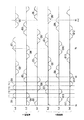
図3に示す12相整流回路1Aにおいて、変圧器11は、一次巻線として3相Y結線の巻線12を有し、二次巻線として3相Y結線の巻線13を有し、三次巻線として3相Δ結線の巻線14を有している。この3相Y結線の巻線13と3相Δ結線の巻線14の組み合わせにより位相差30度の2系統の3相交流電圧が出力される。
上記構成からなる本発明の12相整流回路では、変圧器の一次入力側の各相に交流リアクトル(ACリアクトル)を接続して構成される。
これにより、DCリアクトルを省略し、設置場所および配線の自由度が高いACリアクトルを使用することができる。このため、12相整流回路における配線を簡略化できる。
図1に示す本発明の12相整流回路1が、図3に示す従来技術の12相整流回路1Aと構成上、異なるのは、図3に示す12相整流回路1Aにおいて設備されているDCリアクトル31、32を撤去し、代わりに、図1に示す12相整流回路1において、ACリアクトル2U、2V、2Wを、変圧器11の一次入力側に設備した点である。すなわち、DCリアクトルの代わりに、ACリアクトルを使用した点である。他の構成は図3に示す12相整流回路1Aと同様であるので、同一の要素には同一の符号を付し、重複する説明は省略する。
Claims (1)
- 入力側に3相Y結線または3相Δ結線の巻線を有し、出力側に3相Y結線の巻線および3相Δ結線の巻線を有し位相差30度の3相交流電圧を出力する変圧器と、前記3相Y結線の巻線から出力される交流出力電圧を整流する第1の3相ブリッジ整流回路と、前記3相Δ結線の巻線から出力される交流出力電圧を整流する第2の3相ブリッジ整流回路とを有するとともに、前記第1の3相ブリッジ整流回路の出力側と前記第2の3相ブリッジ整流回路の出力側とを並列に接続して構成される12相整流回路において、
前記変圧器の入力側の3相の各相に交流リアクトルを接続して構成されること
を特徴とする12相整流回路。
Priority Applications (1)
| Application Number | Priority Date | Filing Date | Title |
|---|---|---|---|
| JP2007136578A JP5158408B2 (ja) | 2007-05-23 | 2007-05-23 | 12相整流回路 |
Applications Claiming Priority (1)
| Application Number | Priority Date | Filing Date | Title |
|---|---|---|---|
| JP2007136578A JP5158408B2 (ja) | 2007-05-23 | 2007-05-23 | 12相整流回路 |
Publications (2)
| Publication Number | Publication Date |
|---|---|
| JP2008295155A true JP2008295155A (ja) | 2008-12-04 |
| JP5158408B2 JP5158408B2 (ja) | 2013-03-06 |
Family
ID=40169336
Family Applications (1)
| Application Number | Title | Priority Date | Filing Date |
|---|---|---|---|
| JP2007136578A Expired - Fee Related JP5158408B2 (ja) | 2007-05-23 | 2007-05-23 | 12相整流回路 |
Country Status (1)
| Country | Link |
|---|---|
| JP (1) | JP5158408B2 (ja) |
Cited By (2)
| Publication number | Priority date | Publication date | Assignee | Title |
|---|---|---|---|---|
| WO2016143100A1 (ja) * | 2015-03-11 | 2016-09-15 | 三菱電機株式会社 | コンバータおよび電力変換装置 |
| US9742306B2 (en) | 2015-02-25 | 2017-08-22 | Mitsubishi Electric Corporation | Converter device |
Citations (3)
| Publication number | Priority date | Publication date | Assignee | Title |
|---|---|---|---|---|
| JPH0884476A (ja) * | 1994-09-09 | 1996-03-26 | Toyo Electric Mfg Co Ltd | 多重化整流装置 |
| JP2002044953A (ja) * | 2000-07-27 | 2002-02-08 | Daikin Ind Ltd | 三相半電圧出力形整流装置 |
| JP2002095260A (ja) * | 2000-09-12 | 2002-03-29 | Fuji Electric Systems Co Ltd | 高調波電流抑制型の電力変換装置 |
-
2007
- 2007-05-23 JP JP2007136578A patent/JP5158408B2/ja not_active Expired - Fee Related
Patent Citations (3)
| Publication number | Priority date | Publication date | Assignee | Title |
|---|---|---|---|---|
| JPH0884476A (ja) * | 1994-09-09 | 1996-03-26 | Toyo Electric Mfg Co Ltd | 多重化整流装置 |
| JP2002044953A (ja) * | 2000-07-27 | 2002-02-08 | Daikin Ind Ltd | 三相半電圧出力形整流装置 |
| JP2002095260A (ja) * | 2000-09-12 | 2002-03-29 | Fuji Electric Systems Co Ltd | 高調波電流抑制型の電力変換装置 |
Cited By (7)
| Publication number | Priority date | Publication date | Assignee | Title |
|---|---|---|---|---|
| US9742306B2 (en) | 2015-02-25 | 2017-08-22 | Mitsubishi Electric Corporation | Converter device |
| WO2016143100A1 (ja) * | 2015-03-11 | 2016-09-15 | 三菱電機株式会社 | コンバータおよび電力変換装置 |
| KR20160122727A (ko) | 2015-03-11 | 2016-10-24 | 미쓰비시덴키 가부시키가이샤 | 컨버터 및 전력 변환 장치 |
| JP6058213B1 (ja) * | 2015-03-11 | 2017-01-11 | 三菱電機株式会社 | コンバータおよび電力変換装置 |
| KR101698304B1 (ko) | 2015-03-11 | 2017-01-19 | 미쓰비시덴키 가부시키가이샤 | 컨버터 및 전력 변환 장치 |
| US9641094B2 (en) | 2015-03-11 | 2017-05-02 | Mitsubishi Electric Corporation | Converter and power conversion device having an imbalance detection unit |
| DE112015000404B4 (de) | 2015-03-11 | 2020-01-02 | Mitsubishi Electric Corporation | Wandler und Energiewandlungsvorrichtung |
Also Published As
| Publication number | Publication date |
|---|---|
| JP5158408B2 (ja) | 2013-03-06 |
Similar Documents
| Publication | Publication Date | Title |
|---|---|---|
| CN104253569B (zh) | 发电机励磁装置以及电力转换系统 | |
| JP5652416B2 (ja) | 直列多重電力変換装置 | |
| JP5528858B2 (ja) | 電力変換装置 | |
| JP5655064B2 (ja) | 電気バスセンタリングの方法および装置 | |
| JP5047210B2 (ja) | 電力変換装置 | |
| JP2008178180A (ja) | 整流回路 | |
| JP5158408B2 (ja) | 12相整流回路 | |
| JP6642014B2 (ja) | 電源システム | |
| CN1045143C (zh) | 三相交流和多相整流同时供电的同步发电机 | |
| JP5169590B2 (ja) | 無停電電源装置およびその製造方法 | |
| JP3801305B2 (ja) | 整流装置 | |
| JP5776496B2 (ja) | 電力変換装置 | |
| JP5431826B2 (ja) | Dc/dcコンバータおよび電力変換装置 | |
| JP4153719B2 (ja) | 可変速駆動装置 | |
| JP2008048568A (ja) | 電動機駆動制御装置 | |
| JP6516170B2 (ja) | 改良型非絶縁変圧器を用いたトンネル内のファン駆動用電源回路システム | |
| JP4513185B2 (ja) | 三相半電圧出力形整流装置 | |
| CN103368406A (zh) | 电源装置 | |
| JP5523297B2 (ja) | 電力変換装置 | |
| JP6100452B2 (ja) | 変換装置 | |
| WO2013076852A1 (ja) | 車両用補助電源装置 | |
| JP6591374B2 (ja) | 励磁装置 | |
| JP2017131022A (ja) | 直流高電圧発生装置 | |
| CN106134061B (zh) | 转换器装置 | |
| JP5507919B2 (ja) | 電力変換装置 |
Legal Events
| Date | Code | Title | Description |
|---|---|---|---|
| A621 | Written request for application examination |
Free format text: JAPANESE INTERMEDIATE CODE: A621 Effective date: 20100510 |
|
| RD04 | Notification of resignation of power of attorney |
Free format text: JAPANESE INTERMEDIATE CODE: A7424 Effective date: 20101201 |
|
| A977 | Report on retrieval |
Free format text: JAPANESE INTERMEDIATE CODE: A971007 Effective date: 20120409 |
|
| A131 | Notification of reasons for refusal |
Free format text: JAPANESE INTERMEDIATE CODE: A131 Effective date: 20120417 |
|
| RD02 | Notification of acceptance of power of attorney |
Free format text: JAPANESE INTERMEDIATE CODE: A7422 Effective date: 20120607 |
|
| TRDD | Decision of grant or rejection written | ||
| A01 | Written decision to grant a patent or to grant a registration (utility model) |
Free format text: JAPANESE INTERMEDIATE CODE: A01 Effective date: 20121115 |
|
| A61 | First payment of annual fees (during grant procedure) |
Free format text: JAPANESE INTERMEDIATE CODE: A61 Effective date: 20121128 |
|
| R150 | Certificate of patent or registration of utility model |
Ref document number: 5158408 Country of ref document: JP Free format text: JAPANESE INTERMEDIATE CODE: R150 Free format text: JAPANESE INTERMEDIATE CODE: R150 |
|
| FPAY | Renewal fee payment (event date is renewal date of database) |
Free format text: PAYMENT UNTIL: 20151221 Year of fee payment: 3 |
|
| R250 | Receipt of annual fees |
Free format text: JAPANESE INTERMEDIATE CODE: R250 |
|
| R250 | Receipt of annual fees |
Free format text: JAPANESE INTERMEDIATE CODE: R250 |
|
| R250 | Receipt of annual fees |
Free format text: JAPANESE INTERMEDIATE CODE: R250 |
|
| R250 | Receipt of annual fees |
Free format text: JAPANESE INTERMEDIATE CODE: R250 |
|
| R250 | Receipt of annual fees |
Free format text: JAPANESE INTERMEDIATE CODE: R250 |
|
| LAPS | Cancellation because of no payment of annual fees |