JP2008299545A - Mobile terminal device and access method to external memory thereof - Google Patents
Mobile terminal device and access method to external memory thereof Download PDFInfo
- Publication number
- JP2008299545A JP2008299545A JP2007144273A JP2007144273A JP2008299545A JP 2008299545 A JP2008299545 A JP 2008299545A JP 2007144273 A JP2007144273 A JP 2007144273A JP 2007144273 A JP2007144273 A JP 2007144273A JP 2008299545 A JP2008299545 A JP 2008299545A
- Authority
- JP
- Japan
- Prior art keywords
- external memory
- data
- unit
- area
- control unit
- Prior art date
- Legal status (The legal status is an assumption and is not a legal conclusion. Google has not performed a legal analysis and makes no representation as to the accuracy of the status listed.)
- Granted
Links
Images



Abstract
【課題】セキュリティ領域とデータ領域へのアクセス経路を別コントローラ経由にすることにより、ホスト機器(携帯端末装置)からメモリカード(外部メモリ)への高速アクセスを可能とする。
【解決手段】外部メモリ107とセキュリティ領域用ドライバ113との間に暗号付き外部メモリコントローラ111を介した第1経路と、外部メモリ107とデータ領域用ドライバ114との間にCPRM非対応外部メモリコントローラ112を介した第2経路とを設け、外部メモリ107内部のアクセス領域(セキュリティ領域又はデータ領域)に応じてアクセス経路を切り替え、ホスト機器(携帯電話機1)からメモリカードへのデータ(動画や音楽等)のアクセス速度を向上させる。
【選択図】図5A high-speed access from a host device (portable terminal device) to a memory card (external memory) is made possible by making access paths to a security area and a data area via different controllers.
A first path via an external memory controller with encryption 111 between an external memory 107 and a security area driver 113, and an external memory controller that does not support CPRM between an external memory 107 and a data area driver 114. 112 and a second route via 112, the access route is switched according to the access area (security area or data area) in the external memory 107, and data (video or music) from the host device (mobile phone 1) to the memory card is switched. Etc.) to improve the access speed.
[Selection] Figure 5
Description
本発明は、セキュリティ領域とデータ領域とを含む記憶領域を備えた外部メモリへのアクセスを可能とした携帯端末装置及びその外部メモリへのアクセス方法に関する。 The present invention relates to a portable terminal device capable of accessing an external memory having a storage area including a security area and a data area, and an access method for the external memory.
近年、半導体メモリカードは、小型、軽量、大記憶容量で、読み出し・書き込み速度が早く、デジタルカメラ、携帯オーディオ、電子決済システム、認証システム、及びデジタルコンテンツのネットワーク配信システム等、種々の用途に用いられている。半導体メモリカードの仕様としては、マルチメディアカード(MMC)(登録商標)、スマートメディア(SSFDC)(登録商標)、コンパクトフラッシュ(登録商標)、SD(Secure Digital)メモリカード(登録商標)、及びメモリスティック(登録商標)等がある。 In recent years, semiconductor memory cards have a small size, light weight, large storage capacity, high read / write speed, and are used in various applications such as digital cameras, portable audio, electronic payment systems, authentication systems, and digital content network distribution systems. It has been. The specifications of the semiconductor memory card include a multimedia card (MMC) (registered trademark), a smart media (SSFDC) (registered trademark), a compact flash (registered trademark), an SD (Secure Digital) memory card (registered trademark), and a memory. There is a stick (registered trademark).
これら半導体メモリカードは、著作権等の権利保護の観点からセキュリティ機能が設けられるものが多くなっている。例えば、SDメモリカード等のセキュリティ機能付きメモリカード(以降、外部メモリとも称する)は、CPRM(Content Protection for Recordable Media)対応のメディアとして、現在広く普及するに至っている。 Many of these semiconductor memory cards are provided with a security function from the viewpoint of copyright protection. For example, a memory card with a security function such as an SD memory card (hereinafter also referred to as an external memory) is now widely used as a medium compatible with CPRM (Content Protection for Recordable Media).
セキュリティ機能付きメモリカードは、その内部記憶領域として、セキュリティ領域(保護領域)とデータ領域(ユーザ領域)とに区分して構成されている。このような記憶領域がセキュリティ領域とデータ領域とに区分されたメモリカードと接続されるホスト機器には、セキュリティ領域へアクセスする際、CPRM等の機能付きメモリカードコントローラ(以降、CPRM対応メモリカード(外部メモリ)コントローラと称する)を介してアクセスする必要がある。このため、データ領域へのアクセス時にも、このCPRM対応暗号付きメモリカードコントローラを介してアクセスしている(例えば、特許文献1参照)。
このように、従来、セキュリティ領域とデータ領域とを備えるメモリカード(外部メモリ)において、ホスト機器(携帯端末装置)から、それぞれの領域をアクセスするのに、同じCPRM対応メモリカードコントローラを使用していた。しかしながら、本来、データ領域をアクセスするのにCPRM対応メモリカードコントローラを使用する必要は無く、CPRM非対応メモリカードコントローラの使用が可能である。 Thus, conventionally, in a memory card (external memory) having a security area and a data area, the same CPRM-compatible memory card controller is used to access each area from the host device (mobile terminal device). It was. However, originally, it is not necessary to use a CPRM-compatible memory card controller to access the data area, and a CPRM-incompatible memory card controller can be used.
一方、このようなメモリカードへのアクセスにおいては、基本的に、セキュリティ領域へのアクセスは少なく、データ領域へのアクセスが支配的である。このような状況において、一般に、CPRM対応メモリカードコントローラのメモリへのアクセス速度は、CPRM非対応メモリカードコントローラと比べてはるかに遅い。 On the other hand, in accessing such a memory card, access to the security area is basically small, and access to the data area is dominant. In such a situation, generally, the access speed to the memory of the CPRM compatible memory card controller is much slower than that of the memory card controller not compatible with CPRM.
このため(従来、CPRM対応メモリカードコントローラを使用してデータ領域へのアクセスを行っているため)、データ領域へのアクセス、すなわち、メモリカード全体に対するアクセスが遅くなってしまうという問題が有った。 For this reason (conventionally, since the data area is accessed using a CPRM-compatible memory card controller), there is a problem that access to the data area, that is, access to the entire memory card is delayed. .
本発明は、上記問題に鑑みて成されたものであり、セキュリティ領域とデータ領域へのアクセス経路を別経由にすることにより、携帯端末装置から外部メモリへの高速アクセスを可能とすることを目的とする。 The present invention has been made in view of the above problems, and an object of the present invention is to enable high-speed access from a mobile terminal device to an external memory by using separate access paths to a security area and a data area. And
本発明に係る携帯端末装置は、上記課題を解決するために、セキュリティ領域とデータ領域とを含む記憶領域を備えた外部メモリが接続される外部メモリ接続部と、前記外部メモリの前記セキュリティ領域に対して暗号処理を伴ってアクセス可能な第1の外部メモリ制御部と、前記外部メモリの前記データ領域に対してアクセス可能な第2の外部メモリ制御部と、前記外部メモリ接続部に接続された前記外部メモリに対し、前記第1の外部メモリ制御部又は前記第2の外部メモリ制御部のうちの何れかとを通信可能に切替接続する通信接続切替部と、前記外部メモリの前記セキュリティ領域又は前記データ領域のうちのアクセスされる領域に応じて前記通信接続切替部の接続状態を制御する接続制御部とを備えたことを特徴とする。 In order to solve the above problems, a mobile terminal device according to the present invention includes an external memory connection unit to which an external memory having a storage area including a security area and a data area is connected, and the security area of the external memory. A first external memory control unit that can be accessed with encryption processing, a second external memory control unit that can access the data area of the external memory, and the external memory connection unit A communication connection switching unit that switches and connects the external memory to either the first external memory control unit or the second external memory control unit, and the security area of the external memory or the And a connection control unit that controls a connection state of the communication connection switching unit in accordance with an accessed region of the data region.
また、携帯端末装置では、前記接続制御部は、前記外部メモリに対してアクセスされるデータの種別を判別するデータ判別手段を有し、該データ判別手段で判別される前記アクセスデータの種別に応じて前記通信接続切替部の接続状態を制御することが好ましい。 Further, in the mobile terminal device, the connection control unit has a data determination unit that determines a type of data accessed to the external memory, and corresponds to the type of the access data determined by the data determination unit. It is preferable to control the connection state of the communication connection switching unit.
また、携帯端末装置では、セキュリティ領域用ドライバとデータ領域用ドライバとを備えたドライバ部を備え、前記セキュリティ領域用ドライバは、前記第1の外部メモリ制御部を介して前記外部メモリにアクセスし、前記データ領域用ドライバは、前記第2の外部メモリ制御部を介して前記外部メモリにアクセスすることが好ましい。 The mobile terminal device includes a driver unit including a security area driver and a data area driver, and the security area driver accesses the external memory via the first external memory control unit, The data area driver may access the external memory via the second external memory control unit.
また、本発明に係る携帯端末装置の外部メモリへのアクセス方法は、上記課題を解決するために、外部メモリのセキュリティ領域から復号鍵の読み出しを、第1の外部メモリ制御部にて行うステップと、外部メモリのデータ領域からデータ読み出しを第2の外部メモリ制御部にて行うステップと、読み出されたデータを、前記復号鍵に基づきデコードするステップと、を含むことを特徴とする。 Further, the method for accessing the external memory of the mobile terminal device according to the present invention includes a step of reading the decryption key from the security area of the external memory by the first external memory control unit in order to solve the above problem. A step of reading data from the data area of the external memory by the second external memory control unit; and a step of decoding the read data based on the decryption key.
また、本発明に係る携帯端末装置の外部メモリへのアクセス方法は、入力されたデータが、権利保護されたデータであるか否かを検出するステップと、権利保護されたデータであった場合、第1の外部メモリ制御部を介して暗号鍵を、外部メモリのセキュリティ領域に記録するステップと、権利保護されたデータを、前記暗号鍵に基づきエンコードするステップと、エンコードされた権利保護されたデータを第2の外部メモリ制御部にて外部メモリのデータ領域に記録するステップと、を含むことを特徴とする。 Further, the method for accessing the external memory of the mobile terminal device according to the present invention includes a step of detecting whether the input data is rights-protected data, and if the data is rights-protected data, A step of recording an encryption key in a security area of the external memory via the first external memory control unit; a step of encoding the right-protected data based on the encryption key; and the encoded right-protected data Is recorded in the data area of the external memory by the second external memory control unit.
本発明によれば、携帯端末装置から外部メモリへの高速アクセスが可能となる。 According to the present invention, high-speed access from a mobile terminal device to an external memory is possible.
以下、図面を参照して本発明を実施するための最良の形態を説明する。なお、以下、携帯端末装置として携帯電話機について説明するが、本発明はこれに限定されるものではなく、PHS(Personal Handy phone System)、PDA(Personal Digital Assistant)、ポータブルナビゲーション装置、ノートパソコン等の他の携帯端末装置であっても良い。 The best mode for carrying out the present invention will be described below with reference to the drawings. In the following, a mobile phone will be described as a mobile terminal device, but the present invention is not limited to this, and a PHS (Personal Handy Phone System), a PDA (Personal Digital Assistant), a portable navigation device, a notebook personal computer, etc. Other portable terminal devices may be used.
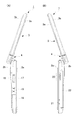
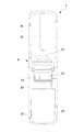
図1から図3により、携帯電話機1における基本構造を説明する。図1は、携帯電話機1を開いた状態(第1開状態)における正面図を示す。また、図2(A)は、携帯電話機1を開いた状態における左側面図を示し、図2(B)は、携帯電話機1を開いた状態における右側面図を示す。また、図3は、携帯電話機1を開いた状態における背面図を示す。
The basic structure of the
携帯電話機1は、操作部側筐体2と、表示部側筐体3とを備える。操作部側筐体2と表示部側筐体3とは2軸ヒンジ機構を備える連結部4を介して連結され、該携帯電話機1を開状態及び閉状態に変形可能とすると共に、開状態及び閉状態それぞれにおいて表示部側筐体3を表状態と裏状態とに切り替えることができる。
The
ここで、閉状態とは、両筐体が互いに重なるように配置された状態であり、開状態とは、両筐体が互いに重ならないように配置された状態をいう。そして、開状態における表状態とは、後述する表示部側筐体3における表面3Aに配置されるディスプレイ30と、操作部側筐体2におけるフロントケース2aに配置される操作キー群11とが同じ側を向くように配置された状態であり、裏状態とは、表示部側筐体3におけるディスプレイ30と操作部側筐体2における操作キー群11とが反対側を向くように配置された状態をいう。また、閉状態における表状態とは、表示部側筐体3におけるディスプレイ30が操作部側筐体2における操作キー群11に対向するように配置された状態であり、閉状態における裏状態とは、表示部側筐体3におけるディスプレイ30が操作部側筐体2における操作キー群11と対向せずに表出した状態である。
Here, the closed state is a state in which both housings are arranged so as to overlap each other, and the open state is a state in which both housings are arranged so as not to overlap each other. In the open state, the
操作部側筐体2は、外面がフロントケース2aとリアケース2bにより構成される。この操作部側筐体2は、フロントケース2a側に、操作キー群(入力操作部とも称する)11と、携帯電話機1の使用者が通話時に発した音声が入力される音声入力部(マイク)12とがそれぞれ露出するように構成される。ここで、操作キー群11は、各種設定や電話帳機能やメール機能等の各種機能を作動させるための機能設定操作キー(ファンクションキーとも称する)13と、電話番号の数字やメール等の文字等を入力するための入力操作キー14と、各種操作における決定や上下左右方向のスクロール等を行う決定操作キー15と、から構成されている。また、マイク12は、操作部側筐体2の長手方向における連結部4側とは反対の外端部側に配置される。つまり、マイク12は、携帯電話機1が開状態において一方の外端部側に配置される。
The outer surface of the operation
操作キー群11を構成する各キーそれぞれには、操作部側筐体2と表示部側筐体3との開閉状態や表裏状態等の変形状態や、起動されているアプリケーションの種類に応じて所定の機能が割り当てられる(キー・アサイン)。携帯電話機1において、操作キー群11を構成する各キーが使用者により押圧されることで、各キーに割り当てられている機能に応じた動作が実行される。
Each key constituting the
操作部側筐体2における一方の側面には、図2(A)に示すように、外部機器(例えば、PCなど)とデータの送受信を行うためのインターフェース16と、ヘッドホン/マイク端子17と、着脱可能な外部メモリのインターフェース18と、バッテリを充電するための充電端子19とが設けられている。なお、インターフェース16、ヘッドホン端子/マイク端子17及びインターフェース18は、不使用時において着脱可能な防塵対策用のキャップで覆われている。
On one side surface of the operation
操作部側筐体2における他方の側面には、図2(B)に示すように、一対のサイドキー20と、撮像時に使用される操作キー21と、電波の受信角度を調整可能な放送波受信用のアンテナ22とが配置される。このサイドキー20には、操作部側筐体2と表示部側筐体3との開閉状態や表裏状態等の変形状態や、起動されているアプリケーションの種類に応じて所定の機能が割り当てられる(キー・アサイン)。ここで、上述と同様に、サイドキー20が使用者により押圧されることで、携帯電話機1においてサイドキー20に割り当てられている機能に応じた動作が実行される。
On the other side of the operation
操作部側筐体2のリアケース2bには、図3に示すように、被写体を撮像するカメラ部23と、被写体に光を照射するライト部24とが露出して配置される。このカメラ部23とライト部24とは、操作部側筐体2における連結部4側に配置される。また、操作部側筐体2におけるリアケース2bには、詳細は後述するバッテリの収容部にバッテリを装着するための開口部が形成されると共に、該開口部を塞ぐようにバッテリーリッド25が配置される。
As shown in FIG. 3, a
また、操作部側筐体2の上端部と表示部側筐体3の下端部とは、図1から図3に示すように、2軸ヒンジ機構を備える連結部4を介して連結される。連結部4における一方の面(裏面)には、図3に示すように、副操作キー群33が該携帯電話機1の幅方向(短手方向)において一列に並んで配置される。この副操作キー群33を構成する各キーそれぞれには、操作部側筐体2と表示部側筐体3との開閉状態や表裏状態等の変形状態や、起動されているアプリケーションの種類に応じて所定の機能が割り当てられる(キー・アサイン)。携帯電話機1において、操作キー群11を構成する各キーが使用者により押圧されることで、各キーに割り当てられている機能に応じた動作が実行される。
Moreover, the upper end part of the operation part side housing | casing 2 and the lower end part of the display part side housing | casing 3 are connected via the
また、表示部側筐体3は、外面がフロントケース3aとリアケース3bにより構成される。表示部側筐体3におけるフロントケース3aには、図1に示すように、各種情報を表示するための所定形状のディスプレイ30と、通話の相手側における音声を出力する音声出力部31とが露出するように配置される。ここで、音声出力部31は、表示部側筐体3の長手方向における連結部4とは反対の外端部側に配置される。つまり、音声出力部31は、携帯電話機1が開状態において他方の端部側に配置される。
Further, the display
また、表示部側筐体3のリアケース3bには、図3に示すように、各種情報を表示するためのサブディスプレイ32が露出して配置される。ディスプレイ30及びサブディスプレイ32それぞれは、液晶パネルと、この液晶パネルを駆動する駆動回路と、この液晶パネルの背面側から光を照射するバックライト等の光源部とから構成される。
Further, as shown in FIG. 3, a sub-display 32 for displaying various types of information is disposed in the
なお、本実施形態においては、連結部4により折り畳み可能な携帯電話機1の説明をしているが、折り畳み式ではなく、操作部側筐体2と表示部側筐体3とを重ね合わせた状態から一方の筐体を一方向にスライドさせるようにしたスライド式や、操作部側筐体2と表示部側筐体3との重ね合せ方向に沿う軸線を中心に一方の筐体を回転させるようにした回転式(ターンタイプ)や、操作部側筐体2と表示部側筐体3とが一つの筐体に配置され連結部を有さない型式(ストレートタイプ)でも良い。
In the present embodiment, the
次に、図4の機能ブロック図を参照して、携帯電話機1の各機能について説明する。携帯電話機1は、図4に示すように、第1の通信規格に準拠する通信網である無線LAN通信網と通信可能な第1の通信部(第1の通信手段)100と、第2の通信規格に準拠する通信網である移動体通信網と通信可能な第2の通信部(第2の通信手段)200と、所定の処理を行う処理部201と、CPU202とを備えている。また、バッテリ90は、第1の通信部100と、第2の通信部200と、処理部201に対して電源を供給している。また、CPU202(ディスプレイ30の表示内容を入力制御部11の操作に応じて変更制御する表示制御手段としての機能を含む)は、第1の通信部(無線部とも称する)100と、第2の通信部(無線部とも称する)200と、処理部201に対して所定の制御を行う。
Next, each function of the
第1の通信部100は、所定の通信方式(無線LAN、例えば、IEEE802.11等に準拠)に基づいて、基地局を介して他の通信端末装置との間で電話による通信やメールによる通信や、インターネット上から所定のURLを有するWebページのダウンロード等を行うアンテナ部81と、送信回路と受信回路(図示せず)とにより構成される通信処理部101と、を備える。
The
また、第2の通信部200は、所定の通信方式(移動体通信網、例えば、CDMA(Code Division Mulitiple Access)2000_1x等)に基づいて、基地局を介して他の通信端末装置との間で電話による通信やメールによる通信や、インターネット上から所定のURLを有するWebページのダウンロード等を行うアンテナ部80(メインアンテナ)と、送信回路と受信回路(図示せず)とにより構成される通信処理部203と、を備える。
In addition, the
また、処理部201は、操作キー群(入力操作部)11と、マイク12と、LCDやOLED等から成るディスプレイ(表示部)30と、音声出力部31と、所定のデータが格納され少なくとも2個のRAM(第1のバッファメモリ及び第2のバッファメモリ)とCPU202の動作プログラムを記憶するROMを備えたメモリ204と、所定の音処理を行う音処理部205と、所定の画像処理を行う画像処理部206と、被写体を撮像するカメラ部23と、着信音等が出力されるスピーカ207と、イヤホン(ヘッドホン)と接続するためのイヤホンジャック104と、外部メモリ107にアクセスする外部メモリコントローラの切替を行う後述のアクセス切替部105と、外部メモリ107と接続するための外部メモリ接続部106等を備えている。尚、操作キー群(入力操作部)11とマイク12とディスプレイ(表示部)30と音声出力部31とメモリ204と音処理部205と画像処理部206とカメラ部23とスピーカ207とイヤホンジャック104とアクセス切替部105とはバスライン102にて接続され、アクセス切替部105と外部メモリ接続部106及び外部メモリ107とは信号線103にてそれぞれ接続される。
In addition, the
次に、図5を参照して、ホスト機器である携帯電話機1による外部メモリ107のデータアクセスを高速にするための構成について説明する。尚、図5は、ホスト機器と外部メモリ107の関係を示したブロック図であり、図4の一点差線で囲まれたブロック(外部メモリ高速アクセス部)108を詳細に示した図である。
Next, a configuration for speeding up data access of the
図5における外部メモリ高速アクセス部108は、アクセス切替部(便宜上のホスト機器)105と、外部メモリ107が接続されて、外部メモリ107とアクセス切替部105とを接続する外部メモリ接続部106とにより構成される。この外部メモリ接続部は、例えばSDメモリカード用コネクタなどにより構成される。
The external memory high-
外部メモリ107は、その内部に、セキュリティ領域(保護領域)109と、データ領域(ユーザ領域)110とを備える。アクセス切替部105は、通信接続切替部115と、CPRM対応外部メモリコントローラ111と、CPRM非対応外部メモリコントローラ112と、ファイルシステム(ドライバ部とも称する)であるセキュリティ領域用ドライバ113及びデータ領域用ドライバ114とにより構成される。尚、アクセス切替部105の制御は、CPU202によって行われる。
The
第1の外部メモリ制御部であるCPRM対応外部メモリコントローラ111は、外部メモリ107のセキュリティ領域に対して暗号処理を伴ってアクセスする。また、著作権等により保護されたデータのデコードやエンコードを行う。第2の外部メモリ制御部であるCPRM非対応外部メモリコントローラ112は、外部メモリ107のデータ領域に対して暗号処理を伴わずにアクセスする。
The CPRM compatible
通信接続切替部115は、CPRM対応外部メモリコントローラ111と外部メモリ接続部106(外部メモリ107のセキュリティ領域)とを、又は、CPRM非対応外部メモリコントローラ112と外部メモリ接続部106(外部メモリ107のデータ領域)とを接続する。尚、この接続制御は、取り扱われるデータが著作権等により保護されたデータであるか否かのデータ種別を判別するデータ判別手段を有する接続制御部であるCPU202により行われる。
The communication
セキュリティ領域用ドライバ113は、CPRM対応外部メモリコントローラ111及び通信接続切替部115を介して外部メモリ107のセキュリティ領域109にアクセスし、データ領域用ドライバ114は、CPRM非対応外部メモリコントローラ112及び通信接続切替部115を介して外部メモリ107のデータ領域110をアクセスする。
The
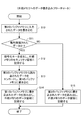
次に、外部メモリ高速アクセス部108の動作について、図6及び図7を参照して説明する。図6は、外部メモリからのデータの読み出し処理の手順を示したフローチャートであり、図7は、外部メモリへのデータの書き込み処理の手順を示したフローチャートである。
Next, the operation of the external memory high-
[外部メモリからのデータの読み出し]
外部メモリ107に記憶されているデータを用いて、ディスプレイ30に画像を表示させたり、音処理部205を介してスピーカ207より音楽などの音響を出力させる場合のように、外部メモリ107からのデータ読み出し要求が発生すると、CPU202は、先ず、外部メモリ接続部106に接続された例えばメモリカードなどの外部メモリ107の属性などに基づき外部メモリ107の整合(認証)が得られていることを前提として、通信接続切替部115を、CPRM対応外部メモリコントローラ111側に切り替え、外部メモリ107のセキュリティ領域109から、外部メモリ接続部106、通信接続切替部115を介して復号鍵などの暗号処理に関わる暗号化データを読み出し(ステップS1)、処理をステップS2に移す。
[Reading data from external memory]
Data from the
ステップS2に移行すると、CPU202は、CPRM対応外部メモリコントローラ111を制御して、セキュリティ領域109から読み出されて暗号化(符号化)されている復号鍵データなどの暗号化データの復号化を行い、処理をステップS3に移す。
In step S2, the
ステップS3に移行すると、CPU202は、通信接続切替部115を、CPRM非対応外部メモリコントローラ112側に切り替え、外部メモリ107のデータ領域から、外部メモリ接続部106、通信接続切替部115、CPRM非対応外部メモリコントローラ112及びデータ領域用ドライバ114を介し、データを読み出して、メモリ204の第1のバッファメモリに書き込み、処理をステップS4に移す。
In step S3, the
ステップS4に移行すると、CPU202は、CPRM対応外部メモリコントローラ111において、セキュリティ領域109からの暗号化データの復号化が完了したか否かを判別する。復号化が完了していないと判別された場合には、処理をステップS4に移し、復号化が完了したと判別された場合には、処理をステップS5に移す。
In step S4, the
ステップS5に移行すると、CPU202は、CPRM対応外部メモリコントローラ111において、暗号化データの復号化が適正であるか否かを判別する。復号化が適正でなかった場合には、処理を終了し、復号化が適正である場合には、処理をステップS6に移す。
In step S5, the
ステップS6に移行すると、CPU202は、CPRM対応外部メモリコントローラ111を制御して、メモリ204の第1のバッファメモリに書き込まれたデータを、セキュリティ領域用ドライバ113にて読み出すとともに、復号化された暗号化データ(ここでは復号鍵データ)に基づき、該読み出されたデータをデコードし、セキュリティ領域用ドライバ113を介してメモリ204の第2のバッファメモリに書き込み、処理をステップS7に移す。
In step S6, the
ステップS7に移行すると、CPU202は、メモリ204の第2のバッファメモリからデータを読み出して、音処理部205を介して出力手段(例えば、スピーカ207やイヤホンジャック104等)に出力する。
In step S7, the
このように、外部メモリ107のセキュリティ領域109から暗号化データ(復号鍵データ)を読み出す外部メモリコントローラ(CPRM対応外部メモリコントローラ111)と外部メモリ107のデータ領域110から出力されるデータを読み出す外部メモリコントローラ(CPRM非対応外部メモリコントローラ112)とを異ならせて構成しているため、外部メモリ107のデータ領域110に記憶されているデータを読み出す際に、メモリへのアクセス速度が遅いCPRM対応外部メモリコントローラを用いずにデータの読み出しを行うことができ、外部メモリへの高速アクセスが可能となる。
Thus, an external memory controller (CPRM-compatible external memory controller 111) that reads encrypted data (decryption key data) from the
また、上記構成によれば、外部メモリ107へのアクセス経路が、暗号処理を伴うアクセス経路(CPRM対応外部メモリコントローラ111を含む経路)と暗号処理を伴わないアクセス経路(CPRM非対応外部メモリコントローラ112を含む経路)とを有して構成されるので、上述したメモリ204の第1のバッファメモリに書き込まれたデータのデコード処理と、上述した外部メモリ107のデータ領域110からのデータの読み出しを、同時に処理することが可能となり、アクセス速度の高速化とともにデコード処理の高速化も可能となる。
Further, according to the above configuration, the access path to the
[外部メモリへのデータの書き込み]
ステップS11にて、DVDやCDやインターネットからのダウンロード等により、取得したデータの外部メモリ107への書き込み要求が発生すると、CPU202は、先ず、入力されたデータをメモリ204の第2のバッファメモリに書き込み、処理をステップS11に移す。
[Write data to external memory]
When a request to write the acquired data to the
ステップS11に移行すると、データ判別手段であるCPU202は、メモリ204の第2のバッファメモリに書き込まれたデータが、著作権などにより権利保護されたデータであるか否かを判別する。権利保護されたデータで無いと判別された場合には、処理をステップS15に移し、通信接続切替部115を、CPRM非対応外部メモリコントローラ112側に切り替え、メモリ204の第2のバッファメモリに書き込まれたデータを読み出し、データ領域用ドライバ114、CPRM非対応外部メモリコントローラ112、通信接続切替部115、及び外部メモリ接続部106を介して、外部メモリ107のデータ領域にデータを書き込む。一方、権利保護されたデータで有ると判別された場合には、処理をステップS12に移す。
In step S11, the
ステップS12に移行すると、CPU202は、通信接続切替部115を、CPRM対応外部メモリコントローラ111側に切り替え、メモリ204の第2のバッファメモリより、セキュリティ領域用ドライバ113を介してCPRM対応外部メモリコントローラ111にデータを読み出し、該CPRM対応外部メモリコントローラ111を制御し、乱数などを用いて暗号キー(暗号鍵)等を生成し、通信接続切替部115及び外部メモリ接続部106を介して外部メモリ107のセキュリティ領域109に暗号キー等を記録し、処理をステップS13に移す。
In step S12, the
ステップS13に移行すると、CPU202は、CPRM対応外部メモリコントローラ111を制御し、メモリ204の第2のバッファメモリから読み出されたデータを生成された暗号キーに対応してエンコードし、セキュリティ領域用ドライバ113を介してメモリ204の第1のバッファメモリに書き込み、処理をステップS14に移す。
In step S13, the
ステップS14に移行すると、CPU202は、通信接続切替部115を、CPRM非対応外部メモリコントローラ112側に切り替え、メモリ204の第1のバッファメモリに書き込まれたデータを、データ領域用ドライバ114、CPRM非対応外部メモリコントローラ112、通信接続切替部115、及び外部メモリ接続部106を介して、読み出して、外部メモリ107のデータ領域に記録する。
In step S14, the
以上、本発明によれば、以下の効果を有する。 As described above, the present invention has the following effects.
メモリカード(外部メモリ)107とセキュリティ領域用ドライバ113との間にCPRM対応メモリカード(外部メモリ)コントローラ111を介した第1経路と、メモリカード(外部メモリ)107とデータ領域用ドライバ114との間にCPRM非対応メモリカード(外部メモリ)コントローラ112を介した第2経路とを設け、メモリカード(外部メモリ)107内部のアクセス領域(セキュリティ領域又はデータ領域)に応じてアクセス経路を切り替えるようにしたので、ホスト機器(携帯電話機1)からメモリカードへのデータ(動画や音楽等)のアクセス速度を向上させることができる。
The first path between the memory card (external memory) 107 and the
また、メモリカード(外部メモリ)107へのアクセススピードが早くなったことにより、カメラの画像データ保存や、メモリカードからの動画/音楽再生等における読み込みスピードのユーザに与えるストレスを軽減することができる。 In addition, since the access speed to the memory card (external memory) 107 is increased, it is possible to reduce the stress on the user of the reading speed in storing image data of the camera and playing back video / music from the memory card. .
以上、実施例について説明したが、本発明はこれに限られるものではない。 As mentioned above, although the Example was described, this invention is not limited to this.
すなわち、実施例では、メモリカード(外部メモリ)内に、セキュリティ領域及びデータ領域が予め存在しているものとして説明しているが、これに限られることは無く、ファイルシステムが、セキュリティ領域及びデータ領域それぞれを、仮想的(論理的)に作り出す構成としても良い。 That is, in the embodiment, it is described that the security area and the data area exist in advance in the memory card (external memory). However, the present invention is not limited to this, and the file system includes the security area and the data area. Each region may be created virtually (logically).
また、メモリカードを外部メモリとして使用しているが、これに限られず、内部メモリとしても良い。また、メモリでなく、ハードディスク等の記憶メディアであっても良い。 Further, although the memory card is used as an external memory, the present invention is not limited to this, and an internal memory may be used. Further, a storage medium such as a hard disk may be used instead of the memory.
1 携帯電話機
2 操作部側筐体
2a、3a フロントケース
2b、3b リアケース
3 表示部側筐体
4 連結部
11 操作キー群
12 マイク
23 カメラ部
30 ディスプレイ
31 音声出力部
80,81 アンテナ
100 第1の通信部
101,203 通信処理部
102 バス
103 信号線
104 イヤホンジャック
105 アクセス切替部
106 外部メモリ接続部
107 外部メモリ(メモリカード)
108 外部メモリ高速アクセス部
109 セキュリティ領域
110 データ領域
111 CPRM対応外部メモリコントローラ
112 CPRM非対応外部メモリコントローラ
113 セキュリティ領域用ドライバ
114 データ領域用ドライバ
115 通信接続切替部
200 第2の通信部
201 処理部
202 CPU(接続制御部)
204 メモリ
205 音処理部
206 画像処理部
207 スピーカ(再生データ出力部)
DESCRIPTION OF
108 External memory high
204
Claims (5)
前記外部メモリの前記セキュリティ領域に対して暗号処理を伴ってアクセス可能な第1の外部メモリ制御部と、
前記外部メモリの前記データ領域に対してアクセス可能な第2の外部メモリ制御部と、
前記外部メモリ接続部に接続された前記外部メモリに対し、前記第1の外部メモリ制御部又は前記第2の外部メモリ制御部のうちの何れかとを通信可能に切替接続する通信接続切替部と、
前記外部メモリの前記セキュリティ領域又は前記データ領域のうちのアクセスされる領域に応じて前記通信接続切替部の接続状態を制御する接続制御部と
を備えたことを特徴とする携帯端末装置。 An external memory connection unit to which an external memory having a storage area including a security area and a data area is connected;
A first external memory control unit capable of accessing the security area of the external memory with encryption processing;
A second external memory control unit capable of accessing the data area of the external memory;
A communication connection switching unit that switches and connects the first external memory control unit or the second external memory control unit to the external memory connected to the external memory connection unit in a communicable manner;
A portable terminal device comprising: a connection control unit that controls a connection state of the communication connection switching unit in accordance with an accessed area of the security area or the data area of the external memory.
ことを特徴とする請求項1に記載の携帯端末装置。 The connection control unit includes a data determining unit that determines a type of data accessed to the external memory, and the communication connection switching unit includes a data determining unit that determines a type of data to be accessed by the data determining unit. The mobile terminal device according to claim 1, wherein the connection state is controlled.
前記セキュリティ領域用ドライバは、前記第1の外部メモリ制御部を介して前記外部メモリにアクセスし、
前記データ領域用ドライバは、前記第2の外部メモリ制御部を介して前記外部メモリにアクセスする
ことを特徴とする請求項1または2に記載の携帯端末装置。 It has a driver part with a security area driver and a data area driver,
The security area driver accesses the external memory via the first external memory control unit,
The mobile terminal device according to claim 1, wherein the data area driver accesses the external memory via the second external memory control unit.
外部メモリのデータ領域から、データの読み出しを第2の外部メモリ制御部にて行うステップと、
読み出されたデータを、前記復号鍵に基づきデコードするステップと、
を含むことを特徴とする携帯端末装置の外部メモリへのアクセス方法。 Reading the decryption key from the security area of the external memory in the first external memory control unit;
Reading out data from the data area of the external memory by the second external memory control unit;
Decoding the read data based on the decryption key;
A method for accessing an external memory of a mobile terminal device.
権利保護されたデータであった場合、第1の外部メモリ制御部を介して暗号鍵を、外部メモリのセキュリティ領域に記録するステップと、
権利保護されたデータを、前記暗号鍵に基づきエンコードするステップと、
エンコードされた権利保護されたデータを、第2の外部メモリ制御部にて外部メモリのデータ領域に記録するステップと、
を含むことを特徴とする携帯端末装置の外部メモリへのアクセス方法。 Detecting whether the input data is rights-protected data;
If it is rights-protected data, recording the encryption key in the security area of the external memory via the first external memory control unit;
Encoding rights-protected data based on the encryption key;
Recording the encoded right-protected data in the data area of the external memory in the second external memory control unit;
A method for accessing an external memory of a mobile terminal device.
Priority Applications (1)
| Application Number | Priority Date | Filing Date | Title |
|---|---|---|---|
| JP2007144273A JP5524445B2 (en) | 2007-05-30 | 2007-05-30 | Mobile terminal device |
Applications Claiming Priority (1)
| Application Number | Priority Date | Filing Date | Title |
|---|---|---|---|
| JP2007144273A JP5524445B2 (en) | 2007-05-30 | 2007-05-30 | Mobile terminal device |
Publications (2)
| Publication Number | Publication Date |
|---|---|
| JP2008299545A true JP2008299545A (en) | 2008-12-11 |
| JP5524445B2 JP5524445B2 (en) | 2014-06-18 |
Family
ID=40173025
Family Applications (1)
| Application Number | Title | Priority Date | Filing Date |
|---|---|---|---|
| JP2007144273A Active JP5524445B2 (en) | 2007-05-30 | 2007-05-30 | Mobile terminal device |
Country Status (1)
| Country | Link |
|---|---|
| JP (1) | JP5524445B2 (en) |
Citations (2)
| Publication number | Priority date | Publication date | Assignee | Title |
|---|---|---|---|---|
| WO2002037239A2 (en) * | 2000-11-02 | 2002-05-10 | Artec Design Group OÜ | Data encryption device based on protocol analysis |
| JP2005011104A (en) * | 2003-06-19 | 2005-01-13 | Toshiba Corp | License control apparatus, program, and method |
-
2007
- 2007-05-30 JP JP2007144273A patent/JP5524445B2/en active Active
Patent Citations (2)
| Publication number | Priority date | Publication date | Assignee | Title |
|---|---|---|---|---|
| WO2002037239A2 (en) * | 2000-11-02 | 2002-05-10 | Artec Design Group OÜ | Data encryption device based on protocol analysis |
| JP2005011104A (en) * | 2003-06-19 | 2005-01-13 | Toshiba Corp | License control apparatus, program, and method |
Also Published As
| Publication number | Publication date |
|---|---|
| JP5524445B2 (en) | 2014-06-18 |
Similar Documents
| Publication | Publication Date | Title |
|---|---|---|
| US9516151B2 (en) | Modular wireless communicator | |
| US8180395B2 (en) | Modular wireless communicator | |
| US7873758B2 (en) | Cellular phone and portable storage device using the same | |
| US9706039B2 (en) | Method for performing cooperative function automatically and device using the same | |
| US20050107120A1 (en) | Mobile storage device with wireless bluetooth module attached thereto | |
| US20170099377A1 (en) | Modular Wireless Communicator | |
| US7856249B2 (en) | Combined mass storage and subscriber identity module providing information security and apparatus for use therewith | |
| JP2009188776A (en) | Electronic book system, mobile terminal with electronic book data receiving function, and electronic book data reproducing program | |
| JP5524445B2 (en) | Mobile terminal device | |
| CN1264373C (en) | Encrypting and de-encrypting method for personal hand-held communication system cell phone identification information | |
| JP4425823B2 (en) | OUTPUT CONTROL DEVICE, VIDEO / AUDIO REPRODUCTION DEVICE, OUTPUT CONTROL METHOD, PROGRAM, AND COMPUTER-READABLE RECORDING MEDIUM CONTAINING THE PROGRAM | |
| EP1569221A1 (en) | Portable information terminal and control method of portable information terminal | |
| JP5006098B2 (en) | Portable electronic device and control method | |
| JP4003919B2 (en) | Data processing apparatus and data processing method | |
| JP2010219840A (en) | Mobile communication terminal | |
| CN100538719C (en) | Information recording/reproducing apparatus | |
| KR100375336B1 (en) | Movable auxiliary storage using a semiconductor memory | |
| JP2008180967A (en) | Sound data processing device | |
| JP2001350657A (en) | Information processing apparatus and information processing method | |
| CN1691684A (en) | Cellular phone terminal and control method of cellular phone terminal | |
| KR20050069327A (en) | Digital cellular phone to back up and restore data making use of external storage medium and method for doing data | |
| JP5951288B2 (en) | Portable terminal device and information processing method | |
| JP2004246634A (en) | Information processing device and information storage device for information processing device | |
| US20080207252A1 (en) | Mobile telephone with direct memory access | |
| KR20050049646A (en) | Apparatus for increasing memory of handheld terminal |
Legal Events
| Date | Code | Title | Description |
|---|---|---|---|
| A621 | Written request for application examination |
Free format text: JAPANESE INTERMEDIATE CODE: A621 Effective date: 20100413 |
|
| A977 | Report on retrieval |
Free format text: JAPANESE INTERMEDIATE CODE: A971007 Effective date: 20120424 |
|
| A131 | Notification of reasons for refusal |
Free format text: JAPANESE INTERMEDIATE CODE: A131 Effective date: 20120508 |
|
| A521 | Written amendment |
Free format text: JAPANESE INTERMEDIATE CODE: A523 Effective date: 20120709 |
|
| A02 | Decision of refusal |
Free format text: JAPANESE INTERMEDIATE CODE: A02 Effective date: 20120807 |
|
| A521 | Written amendment |
Free format text: JAPANESE INTERMEDIATE CODE: A523 Effective date: 20121107 |
|
| A911 | Transfer of reconsideration by examiner before appeal (zenchi) |
Free format text: JAPANESE INTERMEDIATE CODE: A911 Effective date: 20121114 |
|
| A912 | Removal of reconsideration by examiner before appeal (zenchi) |
Free format text: JAPANESE INTERMEDIATE CODE: A912 Effective date: 20130111 |
|
| A521 | Written amendment |
Free format text: JAPANESE INTERMEDIATE CODE: A523 Effective date: 20140114 |
|
| A61 | First payment of annual fees (during grant procedure) |
Free format text: JAPANESE INTERMEDIATE CODE: A61 Effective date: 20140410 |
|
| R150 | Certificate of patent (=grant) or registration of utility model |
Ref document number: 5524445 Country of ref document: JP Free format text: JAPANESE INTERMEDIATE CODE: R150 |