JP2008306830A - Harmonic current compensator - Google Patents
Harmonic current compensator Download PDFInfo
- Publication number
- JP2008306830A JP2008306830A JP2007151275A JP2007151275A JP2008306830A JP 2008306830 A JP2008306830 A JP 2008306830A JP 2007151275 A JP2007151275 A JP 2007151275A JP 2007151275 A JP2007151275 A JP 2007151275A JP 2008306830 A JP2008306830 A JP 2008306830A
- Authority
- JP
- Japan
- Prior art keywords
- filter
- current
- command value
- harmonic
- input
- Prior art date
- Legal status (The legal status is an assumption and is not a legal conclusion. Google has not performed a legal analysis and makes no representation as to the accuracy of the status listed.)
- Granted
Links
- 238000003780 insertion Methods 0.000 abstract description 4
- 230000037431 insertion Effects 0.000 abstract description 4
- 238000001514 detection method Methods 0.000 description 14
- 238000010586 diagram Methods 0.000 description 11
- 239000003990 capacitor Substances 0.000 description 7
- 238000006243 chemical reaction Methods 0.000 description 7
- 238000000034 method Methods 0.000 description 7
- 230000002457 bidirectional effect Effects 0.000 description 5
- 230000001360 synchronised effect Effects 0.000 description 2
- 230000007423 decrease Effects 0.000 description 1
- 239000000284 extract Substances 0.000 description 1
Images

Classifications
-
- Y—GENERAL TAGGING OF NEW TECHNOLOGICAL DEVELOPMENTS; GENERAL TAGGING OF CROSS-SECTIONAL TECHNOLOGIES SPANNING OVER SEVERAL SECTIONS OF THE IPC; TECHNICAL SUBJECTS COVERED BY FORMER USPC CROSS-REFERENCE ART COLLECTIONS [XRACs] AND DIGESTS
- Y02—TECHNOLOGIES OR APPLICATIONS FOR MITIGATION OR ADAPTATION AGAINST CLIMATE CHANGE
- Y02E—REDUCTION OF GREENHOUSE GAS [GHG] EMISSIONS, RELATED TO ENERGY GENERATION, TRANSMISSION OR DISTRIBUTION
- Y02E40/00—Technologies for an efficient electrical power generation, transmission or distribution
- Y02E40/40—Arrangements for reducing harmonics
Landscapes
- Supply And Distribution Of Alternating Current (AREA)
- Control Of Electrical Variables (AREA)
Abstract
Description
本発明は、系統電源に接続された負荷により発生する高調波電流を抽出して、系統の高調波成分を補償する高調波補償装置(アクティブフィルタ)、またはアクティブフィルタ機能を持つ並列型瞬低補償装置における高調波電流補償制御に係り、特にアクティブフィルタからACフィルタを介して高調波補償電流を出力する装置の電流制御に関するものである。 The present invention extracts a harmonic current generated by a load connected to a system power supply and compensates a system harmonic component (active filter) or a parallel type sag compensation having an active filter function. The present invention relates to harmonic current compensation control in a device, and more particularly to current control of a device that outputs a harmonic compensation current from an active filter via an AC filter.
一般に、電力系統においては、系統電源に接続された負荷が発生する高調波電流を補償するアクティブフィルタや、アクティブフィルタ機能を併せ持つ並列型瞬低補償装置などが用いられている。 Generally, in an electric power system, an active filter that compensates a harmonic current generated by a load connected to a system power supply, a parallel type voltage sag compensator having an active filter function, and the like are used.
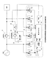
アクティブフィルタ機能を併せ持つ並列型瞬低補償装置の主回路構成例を図3に示す。平常時は、高速スイッチ10を介して電力系統から負荷に電力を供給する。この状態では、インバータ等で構成される交直双方向変換装置20は、アクティブフィルタ機能により負荷から発生する高調波電流を補償、電気二重層キャパシタ30を浮動充電、または停止状態で待機する。また、交直双方向変換装置20は、電力系統の停電時には、高速スイッチ10が切り離されたとき、電気二重層キャパシタ30に蓄積された直流電力を交流電力に変換し、負荷へ無瞬断で電力を供給する。交直双方向変換装置20からはACフィルタ40を通して負荷に高調波補償電流を供給する。
FIG. 3 shows an example of a main circuit configuration of a parallel type sag compensator having an active filter function. During normal times, power is supplied from the power system to the load via the high-
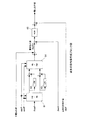
次に、平常時のアクティブフィルタ機能の制御について記述する。図4に、アクティブフィルタ機能を有する並列型瞬低補償装置の制御装置の回路構成を示す。平常時において、負荷が発生する高調波電流を検出する検出手段と、高調波成分を抽出して系統の高調波成分を補償する電流を供給する自励式変換装置とを備える。 Next, normal active filter function control will be described. FIG. 4 shows a circuit configuration of a control device of a parallel type sag compensator having an active filter function. In normal times, it includes a detecting means for detecting a harmonic current generated by a load, and a self-excited conversion device for extracting a harmonic component and supplying a current for compensating the harmonic component of the system.
制御装置50には、系統電圧Vs、系統電流Is、負荷電流Iload、負荷電圧Vload、インバータ出力電流Iinv0、インバータ出力電流Iinv1の各検出器51〜56を持つ。検出した系統電圧Vsは、PLL回路57により系統電源の位相θが検出され、正弦波発生器58により位相θのsinθ成分及びcosθ成分を生成する。指令値作成ブロック59では、検出した系統電圧Vs、系統電流Is、負荷電流Iload、負荷電圧Vload、インバータ出力電流Iinv0、インバータ出力電流Iinv1から高調波補償電流の指令値を作成する。そして、パルス幅変調ブロック(pulse width modulation:PWM)60により高調波補償電流指令値をPWM変調し、交直双方向変換装置20のPWMインバータ制御で高調波補償電流出力を得る。このPWM制御出力から、ACフィルタ30でPWMキャリア信号成分を除去する。
The
負荷が発生する高調波電流の補償を行う電流指令生成手段(指令値作成ブロック59)としては、負荷電流検出型一括高調波検出による補償方法があり、その一例を図5のブロック図に示す。検出した負荷電流Iloadに対して、検出した電源位相θのsinθ成分及びcosθ成分を使用して3φ/dq座標変換部61でdq軸への座標変換を行い、この変換したd軸、q軸成分からローパスフィルタ62,63によって検出する基本波成分を引き算することで高調波成分のみを抽出し、さらにdq/3φ座標変換部64によって逆dq座標変換を行い、これに充電指令値を加算して高調波を補償する電流指令値Iref0を得る。そして、電流指令値Iref0がインバータ出力電流Iinv0に一致するようにACR(自動電流制御)65で電流制御演算を行い、このACR出力を振幅として、PLLにより得られる基準電圧指令値sinθを基準位相とする高調波補償電流指令信号を得る。
As current command generation means (command value creation block 59) for compensating harmonic current generated by a load, there is a compensation method by load current detection type batch harmonic detection, an example of which is shown in the block diagram of FIG. The detected load current Iload is subjected to coordinate conversion to the dq axis by the 3φ / dq coordinate
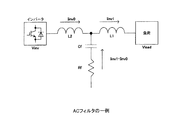
ここで、インバータと負荷の間には、PWM変調に用いるキャリア成分を除去するために、LCL型やLC型のACフィルタ40を介挿する。図6にT型のLCL構成のACフィルタの例を示す。ACフィルタを介挿する場合、ACフィルタにおけるコンデンサCfに流れる電流の影響によって、インバータ出力電流Iinv1を電流指令値Iref通りにすることができない。この結果、アクティブフィルタ機能による高調波補償を行う場合には、高調波補償率が低下してしまうという問題が生じる。
Here, an LCL type or LC
そこで、下記の特許文献1ではACフィルタを考慮した電流指令値Iref1を作成する。この制御方法は、インバータと負荷の間にACフィルタを設置する場合に生じるACフィルタの負荷側のインバータ出力電流Iinv1と電流指令値の電流誤差を、ACフィルタの回路定数から予め算出しておいたACフィルタの影響を除去する伝達関数を用いて補償を行う。ACフィルタ回路定数は、L1:ACフィルタの負荷側インダクタンス[H]、L2:ACフィルタの入力側インダクタンス[H]、Cf:ACフィルタのコンデンサ容量[F]、Rf:ACフィルタの抵抗値[Ω]とする。
Therefore, in the following
図7に特許文献1における指令値作成ブロック図を示す。負荷電圧検出値Vloadと電流指令値Iref0に対して、ACフィルタの影響を除去する伝達関数G(s)を持つ演算要素66、及び伝達関数H(s)をもつ演算要素67を乗じてそれぞれを加算し、これを電流指令値Iref1として、ACR制御を行い、基準電圧指令値を加算することで、指令値を作成する。
FIG. 7 shows a block diagram for creating a command value in
さらに、特許文献1では、電流制御が理想的であると仮定して、ACフィルタの負荷側のインバータ電流検出値Iinv1、及びACフィルタのインバータ(入力)側のインバータ電流検出値Iinv0と、ACフィルタのインダクタンス値L1,L2を用いて、フィードフォワードで電圧降下分の補償を行う方法も提案している。この指令値作成ブロック図を図8に示す。ACフィルタ負荷側のインバータ電流検出値Iinv1に伝達関数sL1をもつ演算要素68を乗じ、インバータ側のインバータ電流検出値Iinv0には伝達関数sL2をもつ演算要素69を乗じてフィードフォワードで、電流指令値Iref0に加算し、指令値を作成する。
特許文献1では、インバータと負荷の間にACフィルタを介挿する場合、コンデンサCfに流れる電流の影響によって生じるACフィルタ負荷側のインバータ出力電流Iinv1と電流指令値の電流誤差を、ACフィルタの回路定数から予め算出しておいた伝達関数を用いて補償を行う。この方式では、ACフィルタのコンデンサCfに流れる電流分を補償している。
In
また、特許文献1では、ACフィルタの負荷側のインバータ電流検出値Iinv0、及びACフィルタのインバータ側のインバータ電流検出値Iinv1と、ACフィルタのインダクタンス値L1,L2を用いて、フィードフォワードで電圧降下分を補償する。この方式は、電流制御が理想的な条件のときに成立するが、実際には演算無駄時間等の影響を受けるため、理想的な制御は難しくなる。
Further, in
そのため、インバータ(入力)側のインバータ電流検出値Iinv0と電流指令値Iref0を用いてACRを行い、負荷側のインバータ電流検出値Iinv1とインバータ(入力)側のインバータ電流検出値Iinv0を用いてフィードフォワードによるLl、L2の電圧降下補償を行うと、制御系が不安定になるという問題がある。 Therefore, ACR is performed using the inverter current detection value Iinv0 on the inverter (input) side and the current command value Iref0, and feedforward is performed using the inverter current detection value Iinv1 on the load side and the inverter current detection value Iinv0 on the inverter (input) side. When the voltage drop compensation of L1 and L2 is performed, the control system becomes unstable.
本発明の目的は、アクティブフィルタからACフィルタを介して高調波補償電流を出力する高調波電流補償装置において、ACフィルタの介挿による電流誤差を補償でき、かつ安定な制御系を実現し、より高精度な電流制御ができる高調波電流補償装置を提供することにある。 An object of the present invention is to realize a stable control system capable of compensating a current error due to the insertion of an AC filter in a harmonic current compensator that outputs a harmonic compensation current from an active filter via an AC filter. It is an object of the present invention to provide a harmonic current compensator capable of highly accurate current control.
本発明は、インバータと負荷の間にACフィルタを介挿した装置において、ACフィルタの入力側の電流指令値(Iref0)の入力に対し、ACフィルタの回路定数から予め求めた伝達関数H(s)を有して演算処理した出力と、ACフィルタの出力側の電圧(Vload)の入力に対し、ACフィルタの回路定数から予め求めた伝達関数G(s)を有して演算処理した出力とを加算して高調波補償電流指令値(Iref1)とすることでACフィルタの介挿による電流誤差を補償する。そして、電流指令値(Iref0)の入力に対し、伝達関数sL1を有して演算処理した出力と、電流指令値(Iref1)の入力に対し、伝達関数sL2を有して演算処理した出力とを加算し、アクティブフィルタの基準電圧指令値に加算して電圧降下を補償することで、安定な制御系を実現し、より高精度な電流制御ができるようにしたもので、以下の構成を特徴とする。 According to the present invention, in an apparatus in which an AC filter is inserted between an inverter and a load, a transfer function H (s) obtained in advance from the circuit constant of the AC filter is input to the input of the current command value (Iref0) on the input side of the AC filter. ) And an output processed with a transfer function G (s) obtained in advance from the circuit constant of the AC filter with respect to the input of the voltage (Vload) on the output side of the AC filter. Is added to obtain a harmonic compensation current command value (Iref1), thereby compensating for a current error due to the insertion of an AC filter. Then, an output that has been processed with the transfer function sL1 for the input of the current command value (Iref0), and an output that has been processed with the transfer function sL2 for the input of the current command value (Iref1). By adding and compensating for the voltage drop by adding to the reference voltage command value of the active filter, a stable control system can be realized and more accurate current control can be achieved. To do.
(1)系統電源に接続された負荷により発生する高調波電流を抽出し、この高調波電流をアクティブフィルタの高調波補償電流指令値にし、アクティブフィルタからT型のLCL構成のACフィルタを介して高調波補償電流を出力する高調波電流補償装置において、
ACフィルタの入力側の電流指令値(Iref0)の入力に対し、ACフィルタの回路定数から予め求めた下記の伝達関数H(s)を有して演算処理した出力と、ACフィルタの出力側の電圧(Vload)の入力に対し、ACフィルタの回路定数から予め求めた下記の伝達関数G(s)を有して演算処理した出力とを加算して前記高調波補償電流指令値(Iref1)とする電流誤差補償手段と、
(1) Harmonic current generated by the load connected to the system power supply is extracted, and this harmonic current is used as the harmonic compensation current command value of the active filter. From the active filter through the AC filter of T-type LCL configuration In the harmonic current compensator that outputs the harmonic compensation current,
With respect to the input of the current command value (Iref0) on the input side of the AC filter, an output processed with the following transfer function H (s) obtained in advance from the circuit constants of the AC filter, and the output side of the AC filter The harmonic compensation current command value (Iref1) is added to the input of the voltage (Vload) by adding an output having the following transfer function G (s) calculated in advance from the circuit constants of the AC filter and performing the arithmetic processing. Current error compensation means for

ただし、L1:ACフィルタの負荷側インダクタンス、L2:ACフィルタの入力側インダクタンス、Cf:ACフィルタのコンデンサ容量、Rf:ACフィルタの抵抗値
前記電流指令値(Iref0)の入力に対し、伝達関数sL1を有して演算処理した出力と、前記電流指令値(Iref1)の入力に対し、伝達関数sL2を有して演算処理した出力とを加算し、アクティブフィルタの基準電圧指令値に加算する電圧降下補償手段と、
を備えたことを特徴とする。
However, L1: Load side inductance of AC filter, L2: Input side inductance of AC filter, Cf: Capacitance of AC filter, Rf: Resistance value of AC filter Transfer function sL1 with respect to the input of current command value (Iref0) The voltage drop that is added to the reference voltage command value of the active filter is added to the input of the current command value (Iref1) and the output that is calculated to have the transfer function sL2 to the input of the current command value (Iref1) Compensation means;
It is provided with.
(2)系統電源に接続された負荷により発生する高調波電流を抽出し、この高調波電流をアクティブフィルタの高調波補償電流指令値にし、アクティブフィルタからL型のLC構成のACフィルタを介して高調波補償電流を出力する高調波電流補償装置において、
ACフィルタの入力側の電流指令値(Iref0)の入力に対し、ACフィルタの回路定数から予め求めた伝達関数sL2(ただし、L2はACフィルタの入力側インダクタンス)を有して演算処理した出力を、アクティブフィルタの基準電圧指令値に加算する電圧降下補償手段を備えたことを特徴とする。
(2) The harmonic current generated by the load connected to the system power supply is extracted, and this harmonic current is used as the harmonic compensation current command value of the active filter, and the active filter is passed through the AC filter of the L-type LC configuration. In the harmonic current compensator that outputs the harmonic compensation current,
For the input of the current command value (Iref0) on the input side of the AC filter, the output having a transfer function sL2 (L2 is the input-side inductance of the AC filter) obtained in advance from the circuit constant of the AC filter is calculated and processed. The voltage drop compensation means for adding to the reference voltage command value of the active filter is provided.
以上のとおり、本発明によれば、ACフィルタ回路定数から予め算出した伝達関数から、無限インパルス応答フィルタを作成し、負荷電圧Vloadと電流指令値Iref0に対して、それぞれの伝達関数から作成したIIRフィルタでフィルタ処理を施すことでACフィルタの介挿による電流誤差を補償し、電流指令値Iref0とIIRフィルタ処理を施した電流指令値Iref1を用いてフィードフォワードでACフィルタのインダクタンス成分L1,L2分による電圧降下補償を行うことで、安定な制御系を実現し、より高精度な電流制御を行うことができる。 As described above, according to the present invention, an infinite impulse response filter is created from the transfer function calculated in advance from the AC filter circuit constants, and the IIR created from the respective transfer functions for the load voltage Vload and the current command value Iref0. By applying a filter process to the filter, a current error due to the AC filter insertion is compensated, and the current command value Iref0 and the current command value Iref1 subjected to the IIR filter process are used to feed the inductance components L1, L2 of the AC filter by feedforward. By performing the voltage drop compensation according to the above, a stable control system can be realized and more accurate current control can be performed.
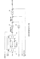
(実施形態1)
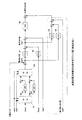
図1は、本発明の実施形態を示す高調波電流補償指令値作成ブロック図であり、ACフィルタをLCL構成とする高調波電流補償装置に適用する場合である。図1中、61〜67は図7のブロックと同様の構成とし、この構成に68,69の演算ブロックを追加したものである。以下、演算ブロック66〜69の構成と電流補償制御を説明する。
(Embodiment 1)
FIG. 1 is a block diagram of harmonic current compensation command value creation showing an embodiment of the present invention, which is applied to a harmonic current compensator with an AC filter having an LCL configuration. In FIG. 1, 61 to 67 have the same configuration as the block of FIG. 7, and 68 and 69 operation blocks are added to this configuration. Hereinafter, the configuration of the calculation blocks 66 to 69 and the current compensation control will be described.
図6に示すLCL構成のACフィルタの回路定数L1、L2、Cf、Rfと、負荷電流Iload、負荷電圧Vload、インバータ出力電流Iinv0、インバータ出力電流Iinv1による回路方程式は、(1)式のように表せる。sはラプラス演算子である。 The circuit equation of the circuit constants L1, L2, Cf, and Rf of the AC filter having the LCL configuration shown in FIG. 6, the load current Iload, the load voltage Vload, the inverter output current Iinv0, and the inverter output current Iinv1 is as shown in Equation (1). I can express. s is a Laplace operator.
ここで、Iinv1、及びIinv0の係数を(2)式のようにおく。 Here, the coefficients of Iinv1 and Iinv0 are set as shown in equation (2).
(1)式、(2)式から、負荷電圧Vloadは(3)式のように表せる。 From equations (1) and (2), the load voltage Vload can be expressed as equation (3).
(3)式をIinv1について解くと、(4)式のように表せる。 When equation (3) is solved for Iinv1, it can be expressed as equation (4).
(4)式より、ACフィルタの影響により、負荷側における電流Iinv1とインバータ側の電流Iinv0が異なる。負荷側における電流Iinv0が電流指令値Iref0になるように、linv0を以下の(5)式のように定める。 From the equation (4), the current Iinv1 on the load side and the current Iinv0 on the inverter side are different due to the influence of the AC filter. Linv0 is determined as in the following equation (5) so that the current Iinv0 on the load side becomes the current command value Iref0.
次に、(4)式に(5)式を代入すると、(6)式のようになり、インバータ出力電流Iinv1と電流指令値Iref0を一致させることができる。 Next, when the formula (5) is substituted into the formula (4), the formula (6) is obtained, and the inverter output current Iinv1 and the current command value Iref0 can be matched.
電流制御が理想的に行われる場合、電流指令値とlinv0は一致するから、入力フィルタを考慮した電流指令値Iref1は以下の(7)式のようにおけばよい。 When the current control is ideally performed, the current command value and linv0 coincide with each other. Therefore, the current command value Iref1 considering the input filter may be expressed by the following equation (7).
したがって、演算ブロック66、及び67の伝達関数G(s)、及び伝達関数H(s)は、以下の(8)式、(9)式に示すものとすることで、負荷側のインバータ出力電流Iinv1と電流指令値の電流誤差を補償することができる。 Therefore, the transfer function G (s) and the transfer function H (s) of the calculation blocks 66 and 67 are expressed by the following equations (8) and (9), so that the inverter output current on the load side The current error between Iinv1 and the current command value can be compensated.
次に、ACフィルタのインダクタンス値L1,L2分の電圧降下補償を行うために、以下の回路方程式を立てる。 Next, in order to perform voltage drop compensation for the inductance values L1 and L2 of the AC filter, the following circuit equation is established.
(10)式、(11)式から、Vloadは以下のように表せる。 From the equations (10) and (11), Vload can be expressed as follows.
ここで、ACフィルタを考慮した電流指令値Iref1とインバータ側のインバータ電流Iinv0と近似し、電流指令値Iref0は負荷側のインバータ電流Iinv1と近似することから、(12)式は以下のように表せる。 Here, since the current command value Iref1 considering the AC filter is approximated to the inverter-side inverter current Iinv0, and the current command value Iref0 is approximated to the load-side inverter current Iinv1, equation (12) can be expressed as follows. .
(13)式におけるsL1・Iref0とsL2・Iref1の項を、伝達関数sL1とsL2をもつ演算ブロック68,69によって求め、これらをフィードフォワードで基準電圧指令値に加算する。基準電圧指令値は系統電圧に同期した定格電圧に相当する正弦波もしくは、正規化した系統電圧を用いる。 The terms sL1 · Iref0 and sL2 · Iref1 in the equation (13) are obtained by operation blocks 68 and 69 having transfer functions sL1 and sL2, and these are added to the reference voltage command value by feedforward. As the reference voltage command value, a sine wave corresponding to a rated voltage synchronized with the system voltage or a normalized system voltage is used.
本実施形態によれば、インバータと負荷の間にACフィルタを介挿した装置において、ACフィルタの影響を除去する伝達関数を用いてACフィルタの負荷側のインバータ出力電流Iinv1と電流指令値の電流誤差を補償し、インバータ電流検出値Iinv0、Iinv1に代えて電流指令値Iref0、Iref1を用いてフィードフォワードでACフィルタのインダクタンス成分の電圧降下補償を行うことで、安定な制御系を実現し、より高精度な電流制御を行うことができる。また、三相上で行うことで、dq軸上の非干渉項も補償できる。 According to this embodiment, in an apparatus in which an AC filter is interposed between an inverter and a load, the inverter output current Iinv1 on the load side of the AC filter and the current command value current are transferred using a transfer function that eliminates the influence of the AC filter. By compensating for the error and compensating the voltage drop of the inductance component of the AC filter by feedforward using the current command values Iref0 and Iref1 instead of the inverter current detection values Iinv0 and Iinv1, a stable control system is realized, and more Highly accurate current control can be performed. Moreover, the non-interference term on the dq axis can be compensated by performing on three phases.
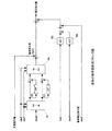
(実施形態2)
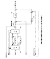
図2は、本発明の実施形態を示す高調波電流補償指令値作成ブロック図であり、ACフィルタをLC構成とする高調波電流補償装置に適用する場合である。同図では、図5と異なる部分は、演算ブロック70を設けた点にある。
(Embodiment 2)
FIG. 2 is a harmonic current compensation command value creation block diagram showing an embodiment of the present invention, which is applied to a harmonic current compensator having an AC filter as an LC configuration. In the figure, the difference from FIG. 5 is that an
ACフィルタがLC構成の場合、ACフィルタを考慮した電流指令値を作成するために解く前記の回路方程式(1)式が成立しないため、ACフィルタの入力側の電流指令値Iref0のみを用いて、以下の式のように、ACフィルタの入力側インダクタンスL2分による電圧降下補償を行う。 When the AC filter has an LC configuration, the circuit equation (1) that is solved to create a current command value considering the AC filter is not satisfied. Therefore, using only the current command value Iref0 on the input side of the AC filter, As shown in the following equation, voltage drop compensation is performed by the input side inductance L2 of the AC filter.
ACフィルタがLC構成の場合は、(14)式におけるsL2・Iref0の項をフィードフォワードで基準電圧指令値に加算する演算ブロック70を設ける。基準電圧指令値は系統電圧に同期した定格電圧に相当する正弦波もしくは、正規化した系統電圧を用いる、
本実施形態によれば、インバータと負荷間におけるACフィルタがLC構成の場合において、インバータ電流検出値ではなく、電流指令値を用いてフィードフォワードでACフィルタのインダクタンス成分の電圧降下補償を行うことで、安定な制御系を実現し、より高精度な電流制御を行うことが可能になる。
When the AC filter has an LC configuration, a
According to this embodiment, when the AC filter between the inverter and the load has an LC configuration, the voltage drop compensation of the inductance component of the AC filter is performed by feedforward using the current command value instead of the inverter current detection value. Therefore, a stable control system can be realized, and more accurate current control can be performed.
10 高速スイッチ
20 交直双方向変換装置
30 電気二重層キャパシタ
40 ACフィルタ
50 制御装置
61、64 座標変換部
62,63 ローパスフィルタ
65 自動電流制御部(ACR)
66、67、68、69 伝達関数ブロック
DESCRIPTION OF
66, 67, 68, 69 Transfer function block
Claims (2)
ACフィルタの入力側の電流指令値(Iref0)の入力に対し、ACフィルタの回路定数から予め求めた下記の伝達関数H(s)を有して演算処理した出力と、ACフィルタの出力側の電圧(Vload)の入力に対し、ACフィルタの回路定数から予め求めた下記の伝達関数G(s)を有して演算処理した出力とを加算して前記高調波補償電流指令値(Iref1)とする電流誤差補償手段と、
前記電流指令値(Iref0)の入力に対し、伝達関数sL1を有して演算処理した出力と、前記電流指令値(Iref1)の入力に対し、伝達関数sL2を有して演算処理した出力とを加算し、アクティブフィルタの基準電圧指令値に加算する電圧降下補償手段と、
を備えたことを特徴とする高調波電流補償装置。 Harmonic current generated by the load connected to the system power supply is extracted, this harmonic current is used as the harmonic compensation current command value of the active filter, and the harmonic compensation from the active filter through the AC filter of T-type LCL configuration In the harmonic current compensator that outputs current,
With respect to the input of the current command value (Iref0) on the input side of the AC filter, an output processed with the following transfer function H (s) obtained in advance from the circuit constants of the AC filter, and the output side of the AC filter The harmonic compensation current command value (Iref1) is added to the input of the voltage (Vload) by adding an output having the following transfer function G (s) calculated in advance from the circuit constants of the AC filter and performing the arithmetic processing. Current error compensation means for
A harmonic current compensator characterized by comprising:
ACフィルタの入力側の電流指令値(Iref0)の入力に対し、ACフィルタの回路定数から予め求めた伝達関数sL2(ただし、L2はACフィルタの入力側インダクタンス)を有して演算処理した出力を、アクティブフィルタの基準電圧指令値に加算する電圧降下補償手段を備えたことを特徴とする高調波電流補償装置。 Harmonic current generated by the load connected to the system power supply is extracted, this harmonic current is used as the harmonic compensation current command value of the active filter, and harmonic compensation is performed from the active filter via the AC filter of the L-type LC configuration. In the harmonic current compensator that outputs current,
For the input of the current command value (Iref0) on the input side of the AC filter, the output having a transfer function sL2 (L2 is the input-side inductance of the AC filter) obtained in advance from the circuit constant of the AC filter is calculated and processed. A harmonic current compensator comprising voltage drop compensation means for adding to the reference voltage command value of the active filter.
Priority Applications (1)
| Application Number | Priority Date | Filing Date | Title |
|---|---|---|---|
| JP2007151275A JP4743168B2 (en) | 2007-06-07 | 2007-06-07 | Harmonic current compensator |
Applications Claiming Priority (1)
| Application Number | Priority Date | Filing Date | Title |
|---|---|---|---|
| JP2007151275A JP4743168B2 (en) | 2007-06-07 | 2007-06-07 | Harmonic current compensator |
Publications (2)
| Publication Number | Publication Date |
|---|---|
| JP2008306830A true JP2008306830A (en) | 2008-12-18 |
| JP4743168B2 JP4743168B2 (en) | 2011-08-10 |
Family
ID=40235038
Family Applications (1)
| Application Number | Title | Priority Date | Filing Date |
|---|---|---|---|
| JP2007151275A Expired - Fee Related JP4743168B2 (en) | 2007-06-07 | 2007-06-07 | Harmonic current compensator |
Country Status (1)
| Country | Link |
|---|---|
| JP (1) | JP4743168B2 (en) |
Cited By (1)
| Publication number | Priority date | Publication date | Assignee | Title |
|---|---|---|---|---|
| CN119448852A (en) * | 2024-11-12 | 2025-02-14 | 苏州弘远电气有限公司 | Motor control device and motor control method for sine wave filter |
Citations (3)
| Publication number | Priority date | Publication date | Assignee | Title |
|---|---|---|---|---|
| JPH06348353A (en) * | 1993-06-11 | 1994-12-22 | Fuji Electric Co Ltd | Active filter |
| JPH09224332A (en) * | 1996-02-15 | 1997-08-26 | Shinko Electric Co Ltd | Power converter |
| JP2002034153A (en) * | 2000-07-14 | 2002-01-31 | Fuji Electric Co Ltd | Control method of active power filter |
-
2007
- 2007-06-07 JP JP2007151275A patent/JP4743168B2/en not_active Expired - Fee Related
Patent Citations (3)
| Publication number | Priority date | Publication date | Assignee | Title |
|---|---|---|---|---|
| JPH06348353A (en) * | 1993-06-11 | 1994-12-22 | Fuji Electric Co Ltd | Active filter |
| JPH09224332A (en) * | 1996-02-15 | 1997-08-26 | Shinko Electric Co Ltd | Power converter |
| JP2002034153A (en) * | 2000-07-14 | 2002-01-31 | Fuji Electric Co Ltd | Control method of active power filter |
Cited By (2)
| Publication number | Priority date | Publication date | Assignee | Title |
|---|---|---|---|---|
| CN119448852A (en) * | 2024-11-12 | 2025-02-14 | 苏州弘远电气有限公司 | Motor control device and motor control method for sine wave filter |
| CN119448852B (en) * | 2024-11-12 | 2025-08-12 | 苏州弘远电气有限公司 | Motor control device and motor control method for sine wave filter |
Also Published As
| Publication number | Publication date |
|---|---|
| JP4743168B2 (en) | 2011-08-10 |
Similar Documents
| Publication | Publication Date | Title |
|---|---|---|
| JP5184153B2 (en) | Single-phase voltage type AC / DC converter and control method for single-phase voltage type AC / DC converter circuit | |
| US12074535B2 (en) | Control device and power conversion device | |
| JP5110960B2 (en) | Grid-connected inverter device | |
| JP4935617B2 (en) | Active filter function device | |
| KR100934311B1 (en) | Inverter device | |
| US12068610B2 (en) | Control device | |
| JP2018182811A (en) | Power converter and control device therefor | |
| JP4743168B2 (en) | Harmonic current compensator | |
| JP4946642B2 (en) | Harmonic current compensator | |
| JP5115730B2 (en) | PWM converter device | |
| JP5109574B2 (en) | Uninterruptible power system | |
| JP5169396B2 (en) | Power converter control circuit | |
| CN104253528B (en) | Converter control device | |
| JP5616411B2 (en) | Single-phase voltage type AC / DC converter | |
| JPH0549172A (en) | Higher harmonic compensator | |
| JP3615966B2 (en) | System linkage inverter device | |
| JP5332229B2 (en) | Instantaneous voltage drop compensation device | |
| KR100222954B1 (en) | Devices and method for operating control angle of pwm converter | |
| JP2658620B2 (en) | Power converter control circuit | |
| JP5497941B2 (en) | Inverter for distributed power supply and control method for inverter for distributed power supply | |
| WO2014050934A1 (en) | Single-phase voltage type ac-dc converter | |
| JP2006304440A (en) | Switch gear of uninterruptible power supply device | |
| WO2014050936A1 (en) | Single-phase voltage type ac-dc converter | |
| WO2015008401A1 (en) | Control device for three-phase four-wire inverter | |
| WO2014050758A1 (en) | Single-phase voltage type ac-dc conversion device |
Legal Events
| Date | Code | Title | Description |
|---|---|---|---|
| A621 | Written request for application examination |
Free format text: JAPANESE INTERMEDIATE CODE: A621 Effective date: 20091112 |
|
| A977 | Report on retrieval |
Free format text: JAPANESE INTERMEDIATE CODE: A971007 Effective date: 20101213 |
|
| A131 | Notification of reasons for refusal |
Free format text: JAPANESE INTERMEDIATE CODE: A131 Effective date: 20110125 |
|
| A521 | Written amendment |
Free format text: JAPANESE INTERMEDIATE CODE: A523 Effective date: 20110322 |
|
| A01 | Written decision to grant a patent or to grant a registration (utility model) |
Free format text: JAPANESE INTERMEDIATE CODE: A01 Effective date: 20110412 |
|
| A61 | First payment of annual fees (during grant procedure) |
Free format text: JAPANESE INTERMEDIATE CODE: A61 Effective date: 20110425 |
|
| FPAY | Renewal fee payment (event date is renewal date of database) |
Free format text: PAYMENT UNTIL: 20140520 Year of fee payment: 3 |
|
| R150 | Certificate of patent or registration of utility model |
Free format text: JAPANESE INTERMEDIATE CODE: R150 |
|
| LAPS | Cancellation because of no payment of annual fees |