JP2008519612A - Catheter balloon system and method - Google Patents
Catheter balloon system and method Download PDFInfo
- Publication number
- JP2008519612A JP2008519612A JP2007540203A JP2007540203A JP2008519612A JP 2008519612 A JP2008519612 A JP 2008519612A JP 2007540203 A JP2007540203 A JP 2007540203A JP 2007540203 A JP2007540203 A JP 2007540203A JP 2008519612 A JP2008519612 A JP 2008519612A
- Authority
- JP
- Japan
- Prior art keywords
- balloon
- branch
- vessel
- stent
- blood vessel
- Prior art date
- Legal status (The legal status is an assumption and is not a legal conclusion. Google has not performed a legal analysis and makes no representation as to the accuracy of the status listed.)
- Withdrawn
Links
- 238000000034 method Methods 0.000 title abstract description 17
- 210000004204 blood vessel Anatomy 0.000 claims abstract description 53
- 239000012530 fluid Substances 0.000 claims description 19
- 238000004891 communication Methods 0.000 claims description 10
- 238000011282 treatment Methods 0.000 abstract description 9
- 239000000463 material Substances 0.000 description 12
- 230000002792 vascular Effects 0.000 description 12
- 208000031481 Pathologic Constriction Diseases 0.000 description 9
- 230000036262 stenosis Effects 0.000 description 9
- 208000037804 stenosis Diseases 0.000 description 9
- -1 polyethylene Polymers 0.000 description 7
- 238000013461 design Methods 0.000 description 6
- 230000003902 lesion Effects 0.000 description 6
- 230000008439 repair process Effects 0.000 description 6
- 239000004952 Polyamide Substances 0.000 description 5
- 229920002647 polyamide Polymers 0.000 description 5
- 210000001367 artery Anatomy 0.000 description 4
- FDPIMTJIUBPUKL-UHFFFAOYSA-N pentan-3-one Chemical compound CCC(=O)CC FDPIMTJIUBPUKL-UHFFFAOYSA-N 0.000 description 4
- 239000004698 Polyethylene Substances 0.000 description 3
- 239000002131 composite material Substances 0.000 description 3
- 238000012986 modification Methods 0.000 description 3
- 230000004048 modification Effects 0.000 description 3
- 229920000573 polyethylene Polymers 0.000 description 3
- 238000001356 surgical procedure Methods 0.000 description 3
- 210000005166 vasculature Anatomy 0.000 description 3
- 238000010586 diagram Methods 0.000 description 2
- 230000010339 dilation Effects 0.000 description 2
- 229920001971 elastomer Polymers 0.000 description 2
- 239000000806 elastomer Substances 0.000 description 2
- 239000007943 implant Substances 0.000 description 2
- 238000003780 insertion Methods 0.000 description 2
- 230000037431 insertion Effects 0.000 description 2
- 239000007788 liquid Substances 0.000 description 2
- 230000001404 mediated effect Effects 0.000 description 2
- 239000000203 mixture Substances 0.000 description 2
- 229920000139 polyethylene terephthalate Polymers 0.000 description 2
- 239000005020 polyethylene terephthalate Substances 0.000 description 2
- 229920002635 polyurethane Polymers 0.000 description 2
- 239000004814 polyurethane Substances 0.000 description 2
- 241000894007 species Species 0.000 description 2
- 230000002966 stenotic effect Effects 0.000 description 2
- 208000031104 Arterial Occlusive disease Diseases 0.000 description 1
- 229920000742 Cotton Polymers 0.000 description 1
- JOYRKODLDBILNP-UHFFFAOYSA-N Ethyl urethane Chemical compound CCOC(N)=O JOYRKODLDBILNP-UHFFFAOYSA-N 0.000 description 1
- 229920000271 Kevlar® Polymers 0.000 description 1
- 239000004677 Nylon Substances 0.000 description 1
- 229930040373 Paraformaldehyde Natural products 0.000 description 1
- 229920002614 Polyether block amide Polymers 0.000 description 1
- 239000004721 Polyphenylene oxide Substances 0.000 description 1
- 239000004743 Polypropylene Substances 0.000 description 1
- 239000000853 adhesive Substances 0.000 description 1
- 230000001070 adhesive effect Effects 0.000 description 1
- 229920006231 aramid fiber Polymers 0.000 description 1
- 208000021328 arterial occlusion Diseases 0.000 description 1
- 230000000712 assembly Effects 0.000 description 1
- 238000000429 assembly Methods 0.000 description 1
- 230000003143 atherosclerotic effect Effects 0.000 description 1
- 230000008901 benefit Effects 0.000 description 1
- 230000008602 contraction Effects 0.000 description 1
- 238000007599 discharging Methods 0.000 description 1
- 238000002594 fluoroscopy Methods 0.000 description 1
- 238000002513 implantation Methods 0.000 description 1
- 239000004761 kevlar Substances 0.000 description 1
- 239000004816 latex Substances 0.000 description 1
- 229920000126 latex Polymers 0.000 description 1
- 238000007726 management method Methods 0.000 description 1
- 229920001778 nylon Polymers 0.000 description 1
- 230000000414 obstructive effect Effects 0.000 description 1
- 230000002093 peripheral effect Effects 0.000 description 1
- 229920000728 polyester Polymers 0.000 description 1
- 229920000570 polyether Polymers 0.000 description 1
- 229920000642 polymer Polymers 0.000 description 1
- 229920006324 polyoxymethylene Polymers 0.000 description 1
- 229920001155 polypropylene Polymers 0.000 description 1
- 229920001296 polysiloxane Polymers 0.000 description 1
- 230000001225 therapeutic effect Effects 0.000 description 1
- 238000002560 therapeutic procedure Methods 0.000 description 1
- 229920001169 thermoplastic Polymers 0.000 description 1
- 239000004416 thermosoftening plastic Substances 0.000 description 1
- 238000012546 transfer Methods 0.000 description 1
- 238000009941 weaving Methods 0.000 description 1
- 210000002268 wool Anatomy 0.000 description 1
Images


Classifications
-
- A—HUMAN NECESSITIES
- A61—MEDICAL OR VETERINARY SCIENCE; HYGIENE
- A61M—DEVICES FOR INTRODUCING MEDIA INTO, OR ONTO, THE BODY; DEVICES FOR TRANSDUCING BODY MEDIA OR FOR TAKING MEDIA FROM THE BODY; DEVICES FOR PRODUCING OR ENDING SLEEP OR STUPOR
- A61M25/00—Catheters; Hollow probes
- A61M25/10—Balloon catheters
- A61M25/1002—Balloon catheters characterised by balloon shape
-
- A—HUMAN NECESSITIES
- A61—MEDICAL OR VETERINARY SCIENCE; HYGIENE
- A61F—FILTERS IMPLANTABLE INTO BLOOD VESSELS; PROSTHESES; DEVICES PROVIDING PATENCY TO, OR PREVENTING COLLAPSING OF, TUBULAR STRUCTURES OF THE BODY, e.g. STENTS; ORTHOPAEDIC, NURSING OR CONTRACEPTIVE DEVICES; FOMENTATION; TREATMENT OR PROTECTION OF EYES OR EARS; BANDAGES, DRESSINGS OR ABSORBENT PADS; FIRST-AID KITS
- A61F2/00—Filters implantable into blood vessels; Prostheses, i.e. artificial substitutes or replacements for parts of the body; Appliances for connecting them with the body; Devices providing patency to, or preventing collapsing of, tubular structures of the body, e.g. stents
- A61F2/82—Devices providing patency to, or preventing collapsing of, tubular structures of the body, e.g. stents
- A61F2/856—Single tubular stent with a side portal passage
-
- A—HUMAN NECESSITIES
- A61—MEDICAL OR VETERINARY SCIENCE; HYGIENE
- A61F—FILTERS IMPLANTABLE INTO BLOOD VESSELS; PROSTHESES; DEVICES PROVIDING PATENCY TO, OR PREVENTING COLLAPSING OF, TUBULAR STRUCTURES OF THE BODY, e.g. STENTS; ORTHOPAEDIC, NURSING OR CONTRACEPTIVE DEVICES; FOMENTATION; TREATMENT OR PROTECTION OF EYES OR EARS; BANDAGES, DRESSINGS OR ABSORBENT PADS; FIRST-AID KITS
- A61F2/00—Filters implantable into blood vessels; Prostheses, i.e. artificial substitutes or replacements for parts of the body; Appliances for connecting them with the body; Devices providing patency to, or preventing collapsing of, tubular structures of the body, e.g. stents
- A61F2/82—Devices providing patency to, or preventing collapsing of, tubular structures of the body, e.g. stents
- A61F2/86—Stents in a form characterised by the wire-like elements; Stents in the form characterised by a net-like or mesh-like structure
- A61F2/90—Stents in a form characterised by the wire-like elements; Stents in the form characterised by a net-like or mesh-like structure characterised by a net-like or mesh-like structure
- A61F2/91—Stents in a form characterised by the wire-like elements; Stents in the form characterised by a net-like or mesh-like structure characterised by a net-like or mesh-like structure made from perforated sheets or tubes, e.g. perforated by laser cuts or etched holes
- A61F2/915—Stents in a form characterised by the wire-like elements; Stents in the form characterised by a net-like or mesh-like structure characterised by a net-like or mesh-like structure made from perforated sheets or tubes, e.g. perforated by laser cuts or etched holes with bands having a meander structure, adjacent bands being connected to each other
-
- A—HUMAN NECESSITIES
- A61—MEDICAL OR VETERINARY SCIENCE; HYGIENE
- A61F—FILTERS IMPLANTABLE INTO BLOOD VESSELS; PROSTHESES; DEVICES PROVIDING PATENCY TO, OR PREVENTING COLLAPSING OF, TUBULAR STRUCTURES OF THE BODY, e.g. STENTS; ORTHOPAEDIC, NURSING OR CONTRACEPTIVE DEVICES; FOMENTATION; TREATMENT OR PROTECTION OF EYES OR EARS; BANDAGES, DRESSINGS OR ABSORBENT PADS; FIRST-AID KITS
- A61F2/00—Filters implantable into blood vessels; Prostheses, i.e. artificial substitutes or replacements for parts of the body; Appliances for connecting them with the body; Devices providing patency to, or preventing collapsing of, tubular structures of the body, e.g. stents
- A61F2/95—Instruments specially adapted for placement or removal of stents or stent-grafts
- A61F2/954—Instruments specially adapted for placement or removal of stents or stent-grafts for placing stents or stent-grafts in a bifurcation
-
- A—HUMAN NECESSITIES
- A61—MEDICAL OR VETERINARY SCIENCE; HYGIENE
- A61F—FILTERS IMPLANTABLE INTO BLOOD VESSELS; PROSTHESES; DEVICES PROVIDING PATENCY TO, OR PREVENTING COLLAPSING OF, TUBULAR STRUCTURES OF THE BODY, e.g. STENTS; ORTHOPAEDIC, NURSING OR CONTRACEPTIVE DEVICES; FOMENTATION; TREATMENT OR PROTECTION OF EYES OR EARS; BANDAGES, DRESSINGS OR ABSORBENT PADS; FIRST-AID KITS
- A61F2/00—Filters implantable into blood vessels; Prostheses, i.e. artificial substitutes or replacements for parts of the body; Appliances for connecting them with the body; Devices providing patency to, or preventing collapsing of, tubular structures of the body, e.g. stents
- A61F2/95—Instruments specially adapted for placement or removal of stents or stent-grafts
- A61F2/958—Inflatable balloons for placing stents or stent-grafts
-
- A—HUMAN NECESSITIES
- A61—MEDICAL OR VETERINARY SCIENCE; HYGIENE
- A61F—FILTERS IMPLANTABLE INTO BLOOD VESSELS; PROSTHESES; DEVICES PROVIDING PATENCY TO, OR PREVENTING COLLAPSING OF, TUBULAR STRUCTURES OF THE BODY, e.g. STENTS; ORTHOPAEDIC, NURSING OR CONTRACEPTIVE DEVICES; FOMENTATION; TREATMENT OR PROTECTION OF EYES OR EARS; BANDAGES, DRESSINGS OR ABSORBENT PADS; FIRST-AID KITS
- A61F2/00—Filters implantable into blood vessels; Prostheses, i.e. artificial substitutes or replacements for parts of the body; Appliances for connecting them with the body; Devices providing patency to, or preventing collapsing of, tubular structures of the body, e.g. stents
- A61F2/02—Prostheses implantable into the body
- A61F2/04—Hollow or tubular parts of organs, e.g. bladders, tracheae, bronchi or bile ducts
- A61F2/06—Blood vessels
- A61F2/07—Stent-grafts
-
- A—HUMAN NECESSITIES
- A61—MEDICAL OR VETERINARY SCIENCE; HYGIENE
- A61F—FILTERS IMPLANTABLE INTO BLOOD VESSELS; PROSTHESES; DEVICES PROVIDING PATENCY TO, OR PREVENTING COLLAPSING OF, TUBULAR STRUCTURES OF THE BODY, e.g. STENTS; ORTHOPAEDIC, NURSING OR CONTRACEPTIVE DEVICES; FOMENTATION; TREATMENT OR PROTECTION OF EYES OR EARS; BANDAGES, DRESSINGS OR ABSORBENT PADS; FIRST-AID KITS
- A61F2/00—Filters implantable into blood vessels; Prostheses, i.e. artificial substitutes or replacements for parts of the body; Appliances for connecting them with the body; Devices providing patency to, or preventing collapsing of, tubular structures of the body, e.g. stents
- A61F2/02—Prostheses implantable into the body
- A61F2/04—Hollow or tubular parts of organs, e.g. bladders, tracheae, bronchi or bile ducts
- A61F2/06—Blood vessels
- A61F2002/061—Blood vessels provided with means for allowing access to secondary lumens
-
- A—HUMAN NECESSITIES
- A61—MEDICAL OR VETERINARY SCIENCE; HYGIENE
- A61F—FILTERS IMPLANTABLE INTO BLOOD VESSELS; PROSTHESES; DEVICES PROVIDING PATENCY TO, OR PREVENTING COLLAPSING OF, TUBULAR STRUCTURES OF THE BODY, e.g. STENTS; ORTHOPAEDIC, NURSING OR CONTRACEPTIVE DEVICES; FOMENTATION; TREATMENT OR PROTECTION OF EYES OR EARS; BANDAGES, DRESSINGS OR ABSORBENT PADS; FIRST-AID KITS
- A61F2/00—Filters implantable into blood vessels; Prostheses, i.e. artificial substitutes or replacements for parts of the body; Appliances for connecting them with the body; Devices providing patency to, or preventing collapsing of, tubular structures of the body, e.g. stents
- A61F2/82—Devices providing patency to, or preventing collapsing of, tubular structures of the body, e.g. stents
- A61F2002/821—Ostial stents
-
- A—HUMAN NECESSITIES
- A61—MEDICAL OR VETERINARY SCIENCE; HYGIENE
- A61F—FILTERS IMPLANTABLE INTO BLOOD VESSELS; PROSTHESES; DEVICES PROVIDING PATENCY TO, OR PREVENTING COLLAPSING OF, TUBULAR STRUCTURES OF THE BODY, e.g. STENTS; ORTHOPAEDIC, NURSING OR CONTRACEPTIVE DEVICES; FOMENTATION; TREATMENT OR PROTECTION OF EYES OR EARS; BANDAGES, DRESSINGS OR ABSORBENT PADS; FIRST-AID KITS
- A61F2/00—Filters implantable into blood vessels; Prostheses, i.e. artificial substitutes or replacements for parts of the body; Appliances for connecting them with the body; Devices providing patency to, or preventing collapsing of, tubular structures of the body, e.g. stents
- A61F2/82—Devices providing patency to, or preventing collapsing of, tubular structures of the body, e.g. stents
- A61F2/86—Stents in a form characterised by the wire-like elements; Stents in the form characterised by a net-like or mesh-like structure
- A61F2/90—Stents in a form characterised by the wire-like elements; Stents in the form characterised by a net-like or mesh-like structure characterised by a net-like or mesh-like structure
- A61F2/91—Stents in a form characterised by the wire-like elements; Stents in the form characterised by a net-like or mesh-like structure characterised by a net-like or mesh-like structure made from perforated sheets or tubes, e.g. perforated by laser cuts or etched holes
- A61F2/915—Stents in a form characterised by the wire-like elements; Stents in the form characterised by a net-like or mesh-like structure characterised by a net-like or mesh-like structure made from perforated sheets or tubes, e.g. perforated by laser cuts or etched holes with bands having a meander structure, adjacent bands being connected to each other
- A61F2002/91508—Stents in a form characterised by the wire-like elements; Stents in the form characterised by a net-like or mesh-like structure characterised by a net-like or mesh-like structure made from perforated sheets or tubes, e.g. perforated by laser cuts or etched holes with bands having a meander structure, adjacent bands being connected to each other the meander having a difference in amplitude along the band
-
- A—HUMAN NECESSITIES
- A61—MEDICAL OR VETERINARY SCIENCE; HYGIENE
- A61F—FILTERS IMPLANTABLE INTO BLOOD VESSELS; PROSTHESES; DEVICES PROVIDING PATENCY TO, OR PREVENTING COLLAPSING OF, TUBULAR STRUCTURES OF THE BODY, e.g. STENTS; ORTHOPAEDIC, NURSING OR CONTRACEPTIVE DEVICES; FOMENTATION; TREATMENT OR PROTECTION OF EYES OR EARS; BANDAGES, DRESSINGS OR ABSORBENT PADS; FIRST-AID KITS
- A61F2/00—Filters implantable into blood vessels; Prostheses, i.e. artificial substitutes or replacements for parts of the body; Appliances for connecting them with the body; Devices providing patency to, or preventing collapsing of, tubular structures of the body, e.g. stents
- A61F2/82—Devices providing patency to, or preventing collapsing of, tubular structures of the body, e.g. stents
- A61F2/86—Stents in a form characterised by the wire-like elements; Stents in the form characterised by a net-like or mesh-like structure
- A61F2/90—Stents in a form characterised by the wire-like elements; Stents in the form characterised by a net-like or mesh-like structure characterised by a net-like or mesh-like structure
- A61F2/91—Stents in a form characterised by the wire-like elements; Stents in the form characterised by a net-like or mesh-like structure characterised by a net-like or mesh-like structure made from perforated sheets or tubes, e.g. perforated by laser cuts or etched holes
- A61F2/915—Stents in a form characterised by the wire-like elements; Stents in the form characterised by a net-like or mesh-like structure characterised by a net-like or mesh-like structure made from perforated sheets or tubes, e.g. perforated by laser cuts or etched holes with bands having a meander structure, adjacent bands being connected to each other
- A61F2002/91516—Stents in a form characterised by the wire-like elements; Stents in the form characterised by a net-like or mesh-like structure characterised by a net-like or mesh-like structure made from perforated sheets or tubes, e.g. perforated by laser cuts or etched holes with bands having a meander structure, adjacent bands being connected to each other the meander having a change in frequency along the band
-
- A—HUMAN NECESSITIES
- A61—MEDICAL OR VETERINARY SCIENCE; HYGIENE
- A61F—FILTERS IMPLANTABLE INTO BLOOD VESSELS; PROSTHESES; DEVICES PROVIDING PATENCY TO, OR PREVENTING COLLAPSING OF, TUBULAR STRUCTURES OF THE BODY, e.g. STENTS; ORTHOPAEDIC, NURSING OR CONTRACEPTIVE DEVICES; FOMENTATION; TREATMENT OR PROTECTION OF EYES OR EARS; BANDAGES, DRESSINGS OR ABSORBENT PADS; FIRST-AID KITS
- A61F2/00—Filters implantable into blood vessels; Prostheses, i.e. artificial substitutes or replacements for parts of the body; Appliances for connecting them with the body; Devices providing patency to, or preventing collapsing of, tubular structures of the body, e.g. stents
- A61F2/82—Devices providing patency to, or preventing collapsing of, tubular structures of the body, e.g. stents
- A61F2/86—Stents in a form characterised by the wire-like elements; Stents in the form characterised by a net-like or mesh-like structure
- A61F2/90—Stents in a form characterised by the wire-like elements; Stents in the form characterised by a net-like or mesh-like structure characterised by a net-like or mesh-like structure
- A61F2/91—Stents in a form characterised by the wire-like elements; Stents in the form characterised by a net-like or mesh-like structure characterised by a net-like or mesh-like structure made from perforated sheets or tubes, e.g. perforated by laser cuts or etched holes
- A61F2/915—Stents in a form characterised by the wire-like elements; Stents in the form characterised by a net-like or mesh-like structure characterised by a net-like or mesh-like structure made from perforated sheets or tubes, e.g. perforated by laser cuts or etched holes with bands having a meander structure, adjacent bands being connected to each other
- A61F2002/91525—Stents in a form characterised by the wire-like elements; Stents in the form characterised by a net-like or mesh-like structure characterised by a net-like or mesh-like structure made from perforated sheets or tubes, e.g. perforated by laser cuts or etched holes with bands having a meander structure, adjacent bands being connected to each other within the whole structure different bands showing different meander characteristics, e.g. frequency or amplitude
-
- A—HUMAN NECESSITIES
- A61—MEDICAL OR VETERINARY SCIENCE; HYGIENE
- A61F—FILTERS IMPLANTABLE INTO BLOOD VESSELS; PROSTHESES; DEVICES PROVIDING PATENCY TO, OR PREVENTING COLLAPSING OF, TUBULAR STRUCTURES OF THE BODY, e.g. STENTS; ORTHOPAEDIC, NURSING OR CONTRACEPTIVE DEVICES; FOMENTATION; TREATMENT OR PROTECTION OF EYES OR EARS; BANDAGES, DRESSINGS OR ABSORBENT PADS; FIRST-AID KITS
- A61F2/00—Filters implantable into blood vessels; Prostheses, i.e. artificial substitutes or replacements for parts of the body; Appliances for connecting them with the body; Devices providing patency to, or preventing collapsing of, tubular structures of the body, e.g. stents
- A61F2/82—Devices providing patency to, or preventing collapsing of, tubular structures of the body, e.g. stents
- A61F2/86—Stents in a form characterised by the wire-like elements; Stents in the form characterised by a net-like or mesh-like structure
- A61F2/90—Stents in a form characterised by the wire-like elements; Stents in the form characterised by a net-like or mesh-like structure characterised by a net-like or mesh-like structure
- A61F2/91—Stents in a form characterised by the wire-like elements; Stents in the form characterised by a net-like or mesh-like structure characterised by a net-like or mesh-like structure made from perforated sheets or tubes, e.g. perforated by laser cuts or etched holes
- A61F2/915—Stents in a form characterised by the wire-like elements; Stents in the form characterised by a net-like or mesh-like structure characterised by a net-like or mesh-like structure made from perforated sheets or tubes, e.g. perforated by laser cuts or etched holes with bands having a meander structure, adjacent bands being connected to each other
- A61F2002/91533—Stents in a form characterised by the wire-like elements; Stents in the form characterised by a net-like or mesh-like structure characterised by a net-like or mesh-like structure made from perforated sheets or tubes, e.g. perforated by laser cuts or etched holes with bands having a meander structure, adjacent bands being connected to each other characterised by the phase between adjacent bands
-
- A—HUMAN NECESSITIES
- A61—MEDICAL OR VETERINARY SCIENCE; HYGIENE
- A61F—FILTERS IMPLANTABLE INTO BLOOD VESSELS; PROSTHESES; DEVICES PROVIDING PATENCY TO, OR PREVENTING COLLAPSING OF, TUBULAR STRUCTURES OF THE BODY, e.g. STENTS; ORTHOPAEDIC, NURSING OR CONTRACEPTIVE DEVICES; FOMENTATION; TREATMENT OR PROTECTION OF EYES OR EARS; BANDAGES, DRESSINGS OR ABSORBENT PADS; FIRST-AID KITS
- A61F2/00—Filters implantable into blood vessels; Prostheses, i.e. artificial substitutes or replacements for parts of the body; Appliances for connecting them with the body; Devices providing patency to, or preventing collapsing of, tubular structures of the body, e.g. stents
- A61F2/82—Devices providing patency to, or preventing collapsing of, tubular structures of the body, e.g. stents
- A61F2/86—Stents in a form characterised by the wire-like elements; Stents in the form characterised by a net-like or mesh-like structure
- A61F2/90—Stents in a form characterised by the wire-like elements; Stents in the form characterised by a net-like or mesh-like structure characterised by a net-like or mesh-like structure
- A61F2/91—Stents in a form characterised by the wire-like elements; Stents in the form characterised by a net-like or mesh-like structure characterised by a net-like or mesh-like structure made from perforated sheets or tubes, e.g. perforated by laser cuts or etched holes
- A61F2/915—Stents in a form characterised by the wire-like elements; Stents in the form characterised by a net-like or mesh-like structure characterised by a net-like or mesh-like structure made from perforated sheets or tubes, e.g. perforated by laser cuts or etched holes with bands having a meander structure, adjacent bands being connected to each other
- A61F2002/9155—Adjacent bands being connected to each other
- A61F2002/91558—Adjacent bands being connected to each other connected peak to peak
-
- A—HUMAN NECESSITIES
- A61—MEDICAL OR VETERINARY SCIENCE; HYGIENE
- A61F—FILTERS IMPLANTABLE INTO BLOOD VESSELS; PROSTHESES; DEVICES PROVIDING PATENCY TO, OR PREVENTING COLLAPSING OF, TUBULAR STRUCTURES OF THE BODY, e.g. STENTS; ORTHOPAEDIC, NURSING OR CONTRACEPTIVE DEVICES; FOMENTATION; TREATMENT OR PROTECTION OF EYES OR EARS; BANDAGES, DRESSINGS OR ABSORBENT PADS; FIRST-AID KITS
- A61F2/00—Filters implantable into blood vessels; Prostheses, i.e. artificial substitutes or replacements for parts of the body; Appliances for connecting them with the body; Devices providing patency to, or preventing collapsing of, tubular structures of the body, e.g. stents
- A61F2/82—Devices providing patency to, or preventing collapsing of, tubular structures of the body, e.g. stents
- A61F2/86—Stents in a form characterised by the wire-like elements; Stents in the form characterised by a net-like or mesh-like structure
- A61F2/90—Stents in a form characterised by the wire-like elements; Stents in the form characterised by a net-like or mesh-like structure characterised by a net-like or mesh-like structure
- A61F2/91—Stents in a form characterised by the wire-like elements; Stents in the form characterised by a net-like or mesh-like structure characterised by a net-like or mesh-like structure made from perforated sheets or tubes, e.g. perforated by laser cuts or etched holes
- A61F2/915—Stents in a form characterised by the wire-like elements; Stents in the form characterised by a net-like or mesh-like structure characterised by a net-like or mesh-like structure made from perforated sheets or tubes, e.g. perforated by laser cuts or etched holes with bands having a meander structure, adjacent bands being connected to each other
- A61F2002/9155—Adjacent bands being connected to each other
- A61F2002/91583—Adjacent bands being connected to each other by a bridge, whereby at least one of its ends is connected along the length of a strut between two consecutive apices within a band
-
- A—HUMAN NECESSITIES
- A61—MEDICAL OR VETERINARY SCIENCE; HYGIENE
- A61F—FILTERS IMPLANTABLE INTO BLOOD VESSELS; PROSTHESES; DEVICES PROVIDING PATENCY TO, OR PREVENTING COLLAPSING OF, TUBULAR STRUCTURES OF THE BODY, e.g. STENTS; ORTHOPAEDIC, NURSING OR CONTRACEPTIVE DEVICES; FOMENTATION; TREATMENT OR PROTECTION OF EYES OR EARS; BANDAGES, DRESSINGS OR ABSORBENT PADS; FIRST-AID KITS
- A61F2250/00—Special features of prostheses classified in groups A61F2/00 - A61F2/26 or A61F2/82 or A61F9/00 or A61F11/00 or subgroups thereof
- A61F2250/0014—Special features of prostheses classified in groups A61F2/00 - A61F2/26 or A61F2/82 or A61F9/00 or A61F11/00 or subgroups thereof having different values of a given property or geometrical feature, e.g. mechanical property or material property, at different locations within the same prosthesis
- A61F2250/0015—Special features of prostheses classified in groups A61F2/00 - A61F2/26 or A61F2/82 or A61F9/00 or A61F11/00 or subgroups thereof having different values of a given property or geometrical feature, e.g. mechanical property or material property, at different locations within the same prosthesis differing in density or specific weight
-
- A—HUMAN NECESSITIES
- A61—MEDICAL OR VETERINARY SCIENCE; HYGIENE
- A61F—FILTERS IMPLANTABLE INTO BLOOD VESSELS; PROSTHESES; DEVICES PROVIDING PATENCY TO, OR PREVENTING COLLAPSING OF, TUBULAR STRUCTURES OF THE BODY, e.g. STENTS; ORTHOPAEDIC, NURSING OR CONTRACEPTIVE DEVICES; FOMENTATION; TREATMENT OR PROTECTION OF EYES OR EARS; BANDAGES, DRESSINGS OR ABSORBENT PADS; FIRST-AID KITS
- A61F2250/00—Special features of prostheses classified in groups A61F2/00 - A61F2/26 or A61F2/82 or A61F9/00 or A61F11/00 or subgroups thereof
- A61F2250/0014—Special features of prostheses classified in groups A61F2/00 - A61F2/26 or A61F2/82 or A61F9/00 or A61F11/00 or subgroups thereof having different values of a given property or geometrical feature, e.g. mechanical property or material property, at different locations within the same prosthesis
- A61F2250/0018—Special features of prostheses classified in groups A61F2/00 - A61F2/26 or A61F2/82 or A61F9/00 or A61F11/00 or subgroups thereof having different values of a given property or geometrical feature, e.g. mechanical property or material property, at different locations within the same prosthesis differing in elasticity, stiffness or compressibility
-
- A—HUMAN NECESSITIES
- A61—MEDICAL OR VETERINARY SCIENCE; HYGIENE
- A61F—FILTERS IMPLANTABLE INTO BLOOD VESSELS; PROSTHESES; DEVICES PROVIDING PATENCY TO, OR PREVENTING COLLAPSING OF, TUBULAR STRUCTURES OF THE BODY, e.g. STENTS; ORTHOPAEDIC, NURSING OR CONTRACEPTIVE DEVICES; FOMENTATION; TREATMENT OR PROTECTION OF EYES OR EARS; BANDAGES, DRESSINGS OR ABSORBENT PADS; FIRST-AID KITS
- A61F2250/00—Special features of prostheses classified in groups A61F2/00 - A61F2/26 or A61F2/82 or A61F9/00 or A61F11/00 or subgroups thereof
- A61F2250/0014—Special features of prostheses classified in groups A61F2/00 - A61F2/26 or A61F2/82 or A61F9/00 or A61F11/00 or subgroups thereof having different values of a given property or geometrical feature, e.g. mechanical property or material property, at different locations within the same prosthesis
- A61F2250/0039—Special features of prostheses classified in groups A61F2/00 - A61F2/26 or A61F2/82 or A61F9/00 or A61F11/00 or subgroups thereof having different values of a given property or geometrical feature, e.g. mechanical property or material property, at different locations within the same prosthesis differing in diameter
-
- A—HUMAN NECESSITIES
- A61—MEDICAL OR VETERINARY SCIENCE; HYGIENE
- A61M—DEVICES FOR INTRODUCING MEDIA INTO, OR ONTO, THE BODY; DEVICES FOR TRANSDUCING BODY MEDIA OR FOR TAKING MEDIA FROM THE BODY; DEVICES FOR PRODUCING OR ENDING SLEEP OR STUPOR
- A61M25/00—Catheters; Hollow probes
- A61M25/10—Balloon catheters
- A61M2025/1043—Balloon catheters with special features or adapted for special applications
- A61M2025/1045—Balloon catheters with special features or adapted for special applications for treating bifurcations, e.g. balloons in y-configuration, separate balloons or special features of the catheter for treating bifurcations
-
- A—HUMAN NECESSITIES
- A61—MEDICAL OR VETERINARY SCIENCE; HYGIENE
- A61M—DEVICES FOR INTRODUCING MEDIA INTO, OR ONTO, THE BODY; DEVICES FOR TRANSDUCING BODY MEDIA OR FOR TAKING MEDIA FROM THE BODY; DEVICES FOR PRODUCING OR ENDING SLEEP OR STUPOR
- A61M25/00—Catheters; Hollow probes
- A61M25/10—Balloon catheters
- A61M2025/1043—Balloon catheters with special features or adapted for special applications
- A61M2025/1056—Balloon catheters with special features or adapted for special applications having guide wire lumens outside the main shaft, i.e. the guide wire lumen is within or on the surface of the balloon
-
- A—HUMAN NECESSITIES
- A61—MEDICAL OR VETERINARY SCIENCE; HYGIENE
- A61M—DEVICES FOR INTRODUCING MEDIA INTO, OR ONTO, THE BODY; DEVICES FOR TRANSDUCING BODY MEDIA OR FOR TAKING MEDIA FROM THE BODY; DEVICES FOR PRODUCING OR ENDING SLEEP OR STUPOR
- A61M25/00—Catheters; Hollow probes
- A61M25/10—Balloon catheters
- A61M2025/1043—Balloon catheters with special features or adapted for special applications
- A61M2025/1059—Balloon catheters with special features or adapted for special applications having different inflatable sections mainly depending on the response to the inflation pressure, e.g. due to different material properties
-
- A—HUMAN NECESSITIES
- A61—MEDICAL OR VETERINARY SCIENCE; HYGIENE
- A61M—DEVICES FOR INTRODUCING MEDIA INTO, OR ONTO, THE BODY; DEVICES FOR TRANSDUCING BODY MEDIA OR FOR TAKING MEDIA FROM THE BODY; DEVICES FOR PRODUCING OR ENDING SLEEP OR STUPOR
- A61M25/00—Catheters; Hollow probes
- A61M25/10—Balloon catheters
- A61M2025/1043—Balloon catheters with special features or adapted for special applications
- A61M2025/1068—Balloon catheters with special features or adapted for special applications having means for varying the length or diameter of the deployed balloon, this variations could be caused by excess pressure
-
- A—HUMAN NECESSITIES
- A61—MEDICAL OR VETERINARY SCIENCE; HYGIENE
- A61M—DEVICES FOR INTRODUCING MEDIA INTO, OR ONTO, THE BODY; DEVICES FOR TRANSDUCING BODY MEDIA OR FOR TAKING MEDIA FROM THE BODY; DEVICES FOR PRODUCING OR ENDING SLEEP OR STUPOR
- A61M25/00—Catheters; Hollow probes
- A61M25/10—Balloon catheters
- A61M2025/1043—Balloon catheters with special features or adapted for special applications
- A61M2025/1086—Balloon catheters with special features or adapted for special applications having a special balloon surface topography, e.g. pores, protuberances, spikes or grooves
-
- A—HUMAN NECESSITIES
- A61—MEDICAL OR VETERINARY SCIENCE; HYGIENE
- A61M—DEVICES FOR INTRODUCING MEDIA INTO, OR ONTO, THE BODY; DEVICES FOR TRANSDUCING BODY MEDIA OR FOR TAKING MEDIA FROM THE BODY; DEVICES FOR PRODUCING OR ENDING SLEEP OR STUPOR
- A61M25/00—Catheters; Hollow probes
- A61M25/10—Balloon catheters
- A61M25/1011—Multiple balloon catheters
Landscapes
- Health & Medical Sciences (AREA)
- Engineering & Computer Science (AREA)
- Biomedical Technology (AREA)
- Heart & Thoracic Surgery (AREA)
- Life Sciences & Earth Sciences (AREA)
- Animal Behavior & Ethology (AREA)
- Veterinary Medicine (AREA)
- Public Health (AREA)
- General Health & Medical Sciences (AREA)
- Transplantation (AREA)
- Vascular Medicine (AREA)
- Oral & Maxillofacial Surgery (AREA)
- Cardiology (AREA)
- Physics & Mathematics (AREA)
- Optics & Photonics (AREA)
- Child & Adolescent Psychology (AREA)
- Biophysics (AREA)
- Pulmonology (AREA)
- Anesthesiology (AREA)
- Hematology (AREA)
- Media Introduction/Drainage Providing Device (AREA)
Abstract
人体内腔の二分岐部の治療用の装置ならびに方法を提供する。本装置は、基端と先端を有する細長いカテーテルを含む。バルーンは、バルーンカテーテルの先端に結合してある。バルーンは、二分岐部の主血管を治療する主血管バルーンと二分岐部の分岐血管を治療する分岐血管バルーンとを含む。分岐血管バルーンは、分岐血管内で非膨張圧潰蛇腹構造からへ膨張蛇腹構造へ膨張させることのできる蛇腹構造を含む。 An apparatus and method for the treatment of a bifurcation of a human body lumen is provided. The apparatus includes an elongated catheter having a proximal end and a distal end. The balloon is coupled to the tip of the balloon catheter. The balloon includes a main blood vessel balloon for treating the main blood vessel at the bifurcation portion and a branch blood vessel balloon for treating the bifurcation blood vessel at the bifurcation portion. The branch vessel balloon includes a bellows structure that can be inflated from a non-inflatable collapsed bellows structure to an inflated bellows structure within the branch vessel.
Description
(関連出願への相互参照)
米国特許法第119条(e)項に従い、本出願の原出願は2003年11月12日出願の米国仮特許出願第60/518,870号と、2004年2月27日出願の米国仮特許出願第60/547,778号と、2004年3月2日出願の米国仮特許出願第60/548,868号と、2003年11月12日出願の同時係属米国特許出願第10/705,247号と、2004年3月17日出願の同時係属米国特許出願第10/802,036号と、2004年4月29日出願の同時係属米国特許出願第10/834,066号と、2004年7月19日出願の同時係属米国特許出願第10/893,278号の優先権の特典を主張するものである。上記に引用した出願の全開示を、本願明細書に参照用に取り込むものとする。
(Cross-reference to related applications)
In accordance with Section 119 (e) of the US Patent Act, the original application for this application is US Provisional Patent Application No. 60 / 518,870 filed on November 12, 2003, and US Provisional Patent filed on February 27, 2004. No. 60 / 547,778, US Provisional Patent Application No. 60 / 548,868 filed March 2, 2004, and Co-pending US Patent Application No. 10 / 705,247 filed November 12, 2003. No. 10 / 802,036 filed Mar. 17, 2004, co-pending US patent application No. 10 / 834,066 filed Apr. 29, 2004, and July 2004. Claims the benefit of priority of co-pending US patent application Ser. No. 10 / 893,278 filed on Jan. 19. The entire disclosure of the above-cited application is incorporated herein by reference.
本発明は、医療用バルーンカテーテルの分野に係り、より詳しくは人体内腔の二分岐部或いはその近傍にステントを給送するシステムに関する。 The present invention relates to the field of medical balloon catheters, and more particularly to a system for delivering a stent to or near a bifurcation of a human body lumen.
バルーンカテーテルは、ステントの有無によらず、狭窄症や閉鎖性狭窄症すなわち人体の様々な部分の狭窄治療に用いられる。数多くの設計からなる装置が、血管修復やステントや移植或いはステント/移植の組み合わせに用いられてきた。様々なカテーテル設計が、狭窄症の拡張と人体内腔内の治療箇所への人工装具の給送に開発されてきた。 Balloon catheters are used to treat stenosis and obstructive stenosis, that is, stenosis of various parts of the human body, regardless of the presence or absence of a stent. Numerous designs of devices have been used for vascular repair, stents and implants or stent / implant combinations. Various catheter designs have been developed to dilate stenosis and deliver the prosthesis to the treatment site within the body lumen.
例示するバルーンカテーテルを含む治療には、経皮経管性血管修復術(PTA)や経皮経管性冠動脈血管修復術(PTCA)が含まれ、それらはアテローム性動脈硬化症血小板が引き起こす種の動脈閉塞を低減するのに用いることができる。これらの治療には案内カテーテルの助けを借りた狭窄部位への誘導ワイヤを介するバルーンカテーテルの送り込みが含まれる。誘導ワイヤは、遠隔切開部から狭窄症部位へ、通常は病巣を跨いで伸ばす。バルーンカテーテルは誘導ワイヤ伝いに送り込み、最終的には病巣を跨いで配置する。 Exemplary treatments involving balloon catheters include percutaneous transluminal vascular repair (PTA) and percutaneous transluminal coronary vascular repair (PTCA), which are the species of atherosclerotic platelets Can be used to reduce arterial occlusion. These therapies include the delivery of a balloon catheter through a guide wire to the stenotic site with the aid of a guide catheter. The guide wire extends from the remote incision to the stenosis site, usually across the lesion. The balloon catheter is sent over a guide wire and finally placed across the lesion.
一旦病巣を跨ぎバルーンカテーテルを適切に配置(例えば、X線透視法により)すると、バルーンを膨張させ、それが狭窄症の血小板を破壊し、動脈断面を増大させる。次にバルーンを収縮させ、誘導ワイヤ伝いに誘導カテーテル内へ患者の体から引き抜く。 Once the balloon catheter is properly positioned (eg, by fluoroscopy) across the lesion, the balloon is inflated, which destroys stenotic platelets and enlarges the arterial cross section. The balloon is then deflated and pulled from the patient's body into the guide catheter over the guide wire.
多くの場合、ステントや他の人工装具を実装して動脈に対するサポートを提供する。この種デバイスを移植すると、そのバルーン上にステントを担持するバルーンカテーテルを狭窄症部位にて展開させる。バルーンと付随人工装具を狭窄箇所に配置し、バルーンを膨張させて周縁方向に拡張し、それによって人工装具を移植する。その後、バルーンを収縮させ、カテーテルと誘導ワイヤを患者から引き抜く。 In many cases, stents and other prostheses are implemented to provide support for the artery. When such a device is implanted, a balloon catheter carrying a stent on the balloon is deployed at the stenosis site. The balloon and associated prosthesis are placed at the stenosis and the balloon is inflated and expanded in the peripheral direction, thereby implanting the prosthesis. The balloon is then deflated and the catheter and guide wire are withdrawn from the patient.
PTCAの管理及び/又は人体内腔内の二分岐部へのステント移植はさらに、管腔部内の狭窄症の効果的な治療に対しさらなる難題を課している。例えば、二分岐部における主血管の拡張が隣接分岐血管の狭窄を引き起こすことがある。この種難題に応えるべく、二分岐血管の両分岐を同時に拡張する試みが推し進められてきた。これらの試みには、2以上のバルーンや2以上の人工装具や二分岐人工装具やそれらの一部組み合わせの展開が含まれる。しかしながら、腔内人工装具の有無によらない複数及び/又は二分岐バルーン、これは以下において個別に或いは集合的に二分岐アセンブリと呼ぶが、その同時展開はアセンブリの正確な配置を必要とする。複数ステントの展開は、二分岐部に隣接する主血管内への本体の配置と、続く別のステントの人体内腔の分岐血管内への個別配置を必要とする。これに対する代替例には、管状本体すなわち胴体と胴体から伸びる二つの管状脚部とを含む専用の二分岐ステントの展開が含まれる。一部の例には、Dereume等に対する米国特許第5,723,004号や、MacGregorに対する米国特許第4,994,071号や、Richter等に対する米国特許第5,755,734号が含まれる。 Management of PTCA and / or stent implantation in bifurcations within the body lumen further poses additional challenges for effective treatment of stenosis within the lumen. For example, dilation of the main vessel at the bifurcation may cause stenosis of adjacent branch vessels. Attempts have been made to simultaneously expand both branches of a bifurcated vessel to meet this type of challenge. These attempts include the deployment of two or more balloons, two or more prostheses, bifurcated prostheses, and some combinations thereof. However, multiple and / or bifurcated balloons with or without an endoluminal prosthesis, hereinafter referred to individually or collectively as bifurcated assemblies, the simultaneous deployment of which requires precise placement of the assembly. The deployment of multiple stents requires placement of the body in the main vessel adjacent to the bifurcation and subsequent placement of another stent in the branch vessel of the human body lumen. An alternative to this involves the deployment of a dedicated bifurcated stent that includes a tubular body or trunk and two tubular legs extending from the trunk. Some examples include US Pat. No. 5,723,004 to Dereume et al., US Pat. No. 4,994,071 to MacGregor, and US Pat. No. 5,755,734 to Richter et al.
二分岐部における改善された確実な治療をもたらす追加の二分岐ステント給送システムが、例えばVardi等への米国特許第6,325,826号やVardi等への米国特許第6,210,429号に開示されている。上記した特許である’826号特許や’429号特許の内容は、参照用に本願明細書に取り込むものとする。 Additional bifurcated stent delivery systems that provide improved and reliable treatment at bifurcations are described, for example, US Pat. No. 6,325,826 to Vardi et al. And US Pat. No. 6,210,429 to Vardi et al. Is disclosed. The contents of the above-mentioned patents, the '826 patent and the' 429 patent, are incorporated herein by reference.
二分岐人体内腔の治療装置ならびに技法をさらに改善する必要性は、依然存在する。例えば、分岐アクセス側の孔及び/又は可伸長分岐部を有するステントと共に使用することのできる追加のステント給送システムに対する必要性がさらに存在する。 There remains a need for further improvements in bifurcated body lumen treatment devices and techniques. For example, there is a further need for additional stent delivery systems that can be used with stents having bifurcated access side holes and / or extendable bifurcations.
本発明は、人体内腔の二分岐部或いはその近傍に腔内人工装具を給送するシステムを含む二分岐人体内腔治療用の装置及び技法に関するものである。人体内腔内の二分岐部にてステントを首尾よくかつ確実に展開させる構成のバルーンカテーテルを備えるシステムと装置と技法を、開示する。加えて、バルーンカテーテルは例えば経皮経管性冠動脈血管修復(PTCA)手術等の血管内閉塞治療用のバルーン血管修復術カテーテルとして用いることができる。 The present invention relates to an apparatus and technique for treating a bifurcated human body lumen including a system for delivering an intraluminal prosthesis to or near a bifurcated portion of a human body lumen. Disclosed are systems, devices, and techniques that include a balloon catheter configured to successfully and reliably deploy a stent at a bifurcation in a body lumen. In addition, the balloon catheter can be used as a balloon vascular repair catheter for intravascular occlusion treatment such as percutaneous transluminal coronary vascular repair (PTCA) surgery.
一態様によれば、本発明は二分岐血管に用いるカテーテルアセンブリを提供する。アセンブリは、基端と先端を有する細長いカテーテル本体と、バルーンカテーテルの先端に結合したバルーンとを含む。バルーンは、二分岐部の主血管を治療する主血管バルーンと、二分岐部の分岐血管を治療する分岐血管バルーンとを含む。分岐血管バルーンは、非膨張圧潰蛇腹構造から分岐血管内へ伸びる膨張蛇腹構造へ膨張させることのできる蛇腹構造を含む。 According to one aspect, the present invention provides a catheter assembly for use with bifurcated vessels. The assembly includes an elongated catheter body having a proximal end and a distal end and a balloon coupled to the distal end of the balloon catheter. The balloon includes a main blood vessel balloon for treating the main blood vessel at the bifurcation portion and a branch blood vessel balloon for treating the bifurcation blood vessel at the bifurcation portion. The branch vessel balloon includes a bellows structure that can be inflated from a non-expandable collapsed bellows structure to an inflated bellows structure that extends into the branch vessel.
別の態様によれば、分岐血管バルーンは蛇腹式折り畳み部を含み、この折り畳み部を非膨張構造において互いにほぼ圧潰し、膨張構造において互いに分離させる。 According to another aspect, the branch vessel balloon includes a bellows-type fold, the folds being substantially crushed from each other in the non-inflatable structure and separated from each other in the inflated structure.
別の態様では、カテーテルアセンブリはバルーン内に配置される二分岐ステントを含む。特に、本発明は主血管部と可伸長分岐血管部とを有する二分岐ステントを含むカテーテルアセンブリを提供する。分岐血管バルーンは、可伸長分岐部にほぼ隣接するよう配置する。膨張時、分岐血管バルーンはステントの可伸長分岐血管部を分岐血管内へ拡張させる。 In another aspect, the catheter assembly includes a bifurcated stent disposed within the balloon. In particular, the present invention provides a catheter assembly that includes a bifurcated stent having a main vessel portion and an extensible branch vessel portion. The branch vessel balloon is disposed so as to be substantially adjacent to the extensible branch. Upon inflation, the branch vessel balloon expands the extensible branch vessel portion of the stent into the branch vessel.
本発明の別の態様では、カテーテルは膨張管腔部を含み、バルーンは膨張管腔部に流体連通する内部を有する。より詳しくは、膨張管腔部は二つの膨張管腔部で構成してある。第1の膨張管腔部は分岐血管バルーンの内部へ流体連通させてある。第2の膨張管腔部は主血管バルーンの内部へ連通させてある。 In another aspect of the invention, the catheter includes an inflation lumen and the balloon has an interior in fluid communication with the inflation lumen. More specifically, the inflation lumen is composed of two inflation lumens. The first inflation lumen is in fluid communication with the interior of the branch vessel balloon. The second inflation lumen is in communication with the main vessel balloon.
本発明の別の態様では、上記した分岐血管バルーンと主血管バルーンを一体型バルーンで構成し、他の実施形態では分岐血管バルーンは主血管バルーンとは別個とする。 In another aspect of the present invention, the aforementioned branch vascular balloon and the main vascular balloon are configured as an integral balloon, and in other embodiments, the branch vascular balloon is separate from the main vascular balloon.
別の態様によれば、本発明は細長いカテーテル本体に結合した側方外装を含むカテーテルアセンブリを備える。側方外装の少なくとも一部がカテーテル本体の先端に沿いかつ分岐血管バルーンに隣接して伸びる。本発明の一部態様では、分岐血管バルーンは側方外装上に配置してある。本発明の別の態様では、側方外装は分岐血管内で自由に使用することができる。加えて、主血管バルーンは二分岐血管内でのカテーテルアセンブリの配置期間中に主血管内で自由に使用することができる。蛇腹構造は主血管バルーンの長手方向軸にほぼ垂直な方向に伸長するよう配向することができる。本発明のさらなる態様では、分岐血管バルーンを側方外装上に配置し、側方外装の長手方向軸にほぼ平行な方向に伸長するよう配向する。 According to another aspect, the invention comprises a catheter assembly that includes a side sheath coupled to an elongated catheter body. At least a portion of the side sheath extends along the tip of the catheter body and adjacent to the branch vessel balloon. In some aspects of the invention, the branch vessel balloon is disposed on the side exterior. In another aspect of the invention, the lateral sheath can be used freely within the branch vessel. In addition, the main vessel balloon can be freely used in the main vessel during the placement of the catheter assembly in the bifurcated vessel. The bellows structure can be oriented to extend in a direction substantially perpendicular to the longitudinal axis of the main vessel balloon. In a further aspect of the invention, the branch vessel balloon is disposed on the side sheath and oriented to extend in a direction substantially parallel to the longitudinal axis of the side sheath.
別の態様では、分岐血管バルーンは主血管バルーン上に脱漏部を備え、別の態様では、本発明は側方外装を含むカテーテルアセンブリを備える。分岐血管バルーンの一端は、側方外装へ摺動可能に固定する。 In another aspect, the bifurcated vascular balloon comprises a leak-out portion on the main vascular balloon, and in another aspect, the invention comprises a catheter assembly that includes a side sheath. One end of the branch vessel balloon is slidably fixed to the side exterior.
追加の態様によれば、本発明のカテーテルアセンブリの蛇腹式折り畳み部の輪郭は膨張方向に沿って見たときにほぼ円形か楕円形か四角形か六角形か八角形のいずれかをなす。加えて、別の態様では、蛇腹式折り畳み部の輪郭は膨張方向に垂直に見たときにほぼ三角形か又は円形をなす。 According to an additional aspect, the contour of the bellows-type fold of the catheter assembly of the present invention is either substantially circular, elliptical, square, hexagonal or octagonal when viewed along the inflation direction. In addition, in another aspect, the contour of the bellows-type fold is substantially triangular or circular when viewed perpendicular to the direction of expansion.
本発明のさらなる態様では、蛇腹式構造は直列接続した複数の流体接続を含む。この直列接続体が、主膨張軸を画成している。別の実施形態では、連続セルは前記直列セルとは異なる大きさを有する。さらなる態様では、セルは完全拡張時にほぼ管状の構造へ合体させるようにしてある。 In a further aspect of the invention, the bellows type structure includes a plurality of fluid connections connected in series. This series connection body defines the main expansion axis. In another embodiment, the continuous cell has a different size than the series cell. In a further aspect, the cell is adapted to merge into a generally tubular structure when fully expanded.
別の態様によれば、本発明は二分岐血管に使用するカテーテルアセンブリを提供する。アセンブリは、基端と先端を有する細長いカテーテル本体と、バルーンカテーテルの先端に結合したバルーンとを含む。バルーンは、二分岐部の主血管を治療する主血管バルーンと、二分岐部の分岐血管を治療する分岐血管バルーンとを含む。分岐血管バルーンは、直列接続した複数の流体接続セルを備え、この直列接続体が主膨張軸を画成する。分岐血管バルーンの膨張時、主膨張軸に沿う膨張は主膨張軸にほぼ垂直な半径方向の膨張よりも大きい。 According to another aspect, the present invention provides a catheter assembly for use with bifurcated vessels. The assembly includes an elongated catheter body having a proximal end and a distal end and a balloon coupled to the distal end of the balloon catheter. The balloon includes a main blood vessel balloon for treating the main blood vessel at the bifurcation portion and a branch blood vessel balloon for treating the bifurcation blood vessel at the bifurcation portion. The branch vessel balloon includes a plurality of fluid connection cells connected in series, and the series connection body defines a main expansion axis. When the branch vessel balloon is inflated, the inflation along the main inflation axis is greater than the radial inflation substantially perpendicular to the main inflation axis.
本発明のさらなる態様は、前記直列セルとは大きさが異なる連続セルを有するカテーテルアセンブリを提供する。別の態様では、セルは完全拡張時にほぼ管状の構造へ合体されるようにしてある。 A further aspect of the present invention provides a catheter assembly having a continuous cell that is different in size from the series cell. In another aspect, the cells are merged into a generally tubular structure when fully expanded.
別の態様によれば、本発明は人体内腔の二分岐部を治療する方法を提供する。二分岐部は、主血管と分岐血管とを含む。本方法は、バルーンとステントを主血管へ導入するステップで、バルーンが少なくとも一つの蛇腹式膨張部を含み、この蛇腹式膨張部が複数の蛇腹式折り畳み部を備える前記ステップと、前記アセンブリを二分岐部に配置するステップと、前記バルーンを膨張させてステントを主血管内で拡張するステップとを含む。 According to another aspect, the present invention provides a method of treating a bifurcation of a human body lumen. The bifurcated portion includes a main blood vessel and a branch blood vessel. The method includes the step of introducing a balloon and a stent into the main vessel, wherein the balloon includes at least one bellows-type inflatable portion, the bellows-type inflatable portion comprising a plurality of bellows-type folded portions, and the assembly. Placing the bifurcation and inflating the balloon to expand the stent within the main vessel.
本発明の別の態様は、膨張ステップがステントの一部の分岐血管へ向けた外方膨張を含む体内二分岐部の治療方法を提供する。別の態様は、蛇腹式構造がステントの一部を分岐血管へ向け外方拡張させる方法を提供する。上記人体内腔は、血管とすることができる。 Another aspect of the present invention provides a method for treating a bifurcation in the body, wherein the expansion step includes outward expansion towards some branch vessels of the stent. Another aspect provides a method in which a bellows-type structure expands a portion of a stent outwardly into a branch vessel. The human body lumen can be a blood vessel.
本発明を、添付図面を参照し例示としてのみここに説明する。ここで図面を詳しく格別に参照するに、図示の詳細は例示としてであり、本発明の好適な実施形態の例示説明目的のためだけであり、本発明の原理及び概念的態様の最も有用で即理解可能な説明と信ずるものを提供するよう提示するものであることを強調しておく。 The invention will now be described by way of example only with reference to the accompanying drawings. Referring now more particularly to the drawings, the details shown are by way of example only and for purposes of illustration of the preferred embodiment of the present invention and are the most useful and instant of the principles and conceptual aspects of the present invention. Emphasize that it is presented to provide an understandable explanation and what to believe.
本発明は、血管内の閉塞を治療するバルーン血管修復カテーテル等のバルーンカテーテルに関する。バルーンカテーテルは、単独で或いはステントや人工装具や移植片と共に使用することができる。この種ステント給送システムは、人体内腔内、特に血管の二分岐部へのステントの配置に使用することができる。給送対象である好適なステントは、概ね主血管系だけでなく分岐血管系の一部を少なくとも一部覆うよう構成してある。一般に、多種多様なステント及び展開方法が本発明のステント給送システム実施形態と共に使用でき、本発明は如何なる特定のステント設計或いは構成にも限定されないと理解されたい。本発明給送システムに使用できるステント種の例は、例えば、Vardi等への米国特許第6,210,429号やVardi等への米国特許第6,325,826号や、「二分岐血管用突出分岐部付きステント(Stent With a Protruding Branch Portion For Bifurcated Vessels)」と題する米国特許出願第2004−0138737号や、「二分岐血管用突出分岐部付きステント(Stent With a Protruding Branch Portion for Bifurcated Vessels)」と題する米国特許出願第2004−0212940号に開示されており、それらの内容は全て本願明細書に参照用に取り込むものとする。一般に、前述のステントは血管の二分岐部にて分岐血管内へ伸長可能に構成したステントの長さに沿う或る点に位置する分岐部を含む。一旦ステントを主血管内の所定位置とし、分岐部を側方分岐血管に整列配置すると、ステントを伸長させることができ、本発明原理に従う給送システムは特にステント分岐部を側方分岐血管内へ拡張できるようにしてある。分岐部を含むステントは、一元拡張或いは多元拡張をもって拡張させることができる。 The present invention relates to a balloon catheter such as a balloon blood vessel repair catheter for treating occlusion in a blood vessel. The balloon catheter can be used alone or with a stent, prosthesis, or graft. This type of stent delivery system can be used to place a stent within a human body lumen, particularly at a bifurcation of a blood vessel. Suitable stents to be delivered are generally configured to cover at least a portion of the branch vasculature as well as the main vasculature. In general, it should be understood that a wide variety of stents and deployment methods can be used with the stent delivery system embodiments of the present invention, and the present invention is not limited to any particular stent design or configuration. Examples of stent types that can be used in the delivery system of the present invention include, for example, US Pat. No. 6,210,429 to Vardi et al., US Pat. No. 6,325,826 to Vardi et al. US Patent Application No. 2004-0138737 entitled “Stent With a Producing Branch For Bistressed Vessels” or “Stent With a Prosthetic Branstruding Brenched Brenched Brenched Brenched Bransted Branched Vessel Strain No. 2004-0212940, the entire contents of which are incorporated herein by reference. In general, such stents include a bifurcation located at a point along the length of the stent that is configured to extend into the bifurcated vessel at the bifurcation of the vessel. Once the stent is in place in the main vessel and the bifurcation is aligned with the side branch vessel, the stent can be extended, and the delivery system according to the principles of the present invention is particularly suitable for placing the stent bifurcation into the side branch vessel. It can be extended. A stent including a bifurcation can be expanded with one-way expansion or multiple-way expansion.
本発明原理に従って使用するバルーンカテーテルシステムとステント給送システム及び方法は、血管系内の二分岐部、例えば分岐血管が主血管から延出する部分の治療種に関するものである。このシステムは分岐バルーンの分岐血管内への伸長をもたらし、好ましくは例えば前記した特許ならびに応用例に開示される如くステントの可伸長分岐部を分岐血管内へ展開させる。システムならびに方法の実施形態を、ここでより詳しく説明する。一般に、本発明原理に従えば、分岐血管内へのバルーンの拡張、より詳しくは分岐ステント構造の分岐血管内への拡張はここに説明し図示する蛇腹式バルーンにより達成することができる。蛇腹式バルーンは、主に軸方向、例えばその主膨張軸に沿って拡張可能に構成してあり、分岐血管内にそれを伸長できるようにしかつ/又は前記したステントの可伸長分岐構造を展開させることができる。 The balloon catheter system and stent delivery system and method used in accordance with the principles of the present invention relate to a therapeutic species for bifurcations in the vasculature, for example, where the branch vessel extends from the main vessel. This system provides extension of the branch balloon into the branch vessel, preferably deploying the expandable branch of the stent into the branch vessel as disclosed, for example, in the aforementioned patents and applications. System and method embodiments are now described in greater detail. In general, in accordance with the principles of the present invention, dilatation of the balloon into the branch vessel, and more particularly, dilation of the bifurcated stent structure into the bifurcation vessel can be accomplished with the bellows-type balloon described and illustrated herein. The bellows balloon is configured to be expandable primarily axially, eg, along its main inflation axis, to allow it to expand into the branch vessel and / or to deploy the expandable branch structure of the stent described above. be able to.
本発明原理に従い、ここに蛇腹式バルーンの実施形態を図示し説明する。幾つかの実施形態では、蛇腹式バルーンは側方外装カテーテルに結合させるか或いは一体化させることができる。さもなくば、蛇腹式バルーンは以下により詳しく説明する如く主バルーンカテーテルに結合させるか或いは一体化させることができる。加えて、幾つかの実施形態(図11乃至図17参照)では、蛇腹式バルーンをカテーテル或いは外装へ摺動可能に取り付け、蛇腹式バルーンの軸方向或いは長手方向の膨張に対応させることができる。 In accordance with the principles of the present invention, an embodiment of a bellows balloon is illustrated and described herein. In some embodiments, the bellows balloon can be coupled to or integrated with a side sheath catheter. Otherwise, the bellows-type balloon can be coupled to or integrated with the main balloon catheter as described in more detail below. In addition, in some embodiments (see FIGS. 11-17), the bellows balloon can be slidably attached to a catheter or sheath to accommodate axial or longitudinal expansion of the bellows balloon.
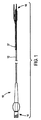
本発明に従い構成したステント給送システム10の一実施形態の例示図が、図1に示してある。ステント給送システム10は概ね基端14から先端16へ伸びる細長い主カテーテル軸12を備える。図示2に最もよく示す如く、先端16は二つの分岐部、すなわち主血管分岐部18と主カテーテル軸12から分岐して外れる側方分岐外装20とを備える二分岐先端構造を有する。
An illustrative view of one embodiment of a
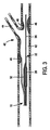
バルーン26は、以下により詳しく説明する如く、概ね蛇腹式バルーンを備える可膨張部32を含む。図示のバルーン26は、先端16に隣接させて主血管分岐部18に取り付けられ、第1と第2の分岐部27,30を有する二分岐バルーンとすることができる。バルーン26の第1の分岐部27は、細長い可膨張部28を備える。バルーン26の第2の分岐部30は、第2の可膨張部すなわち蛇腹式バルーンからなる軸方向可膨張部32を備える。第2の分岐部30は第1の分岐部27をバルーン26の基端側へ分岐して外れ、細長い可膨張部28にほぼ隣接して伸びる膨張管腔部を含む。第2の分岐部30の先端は、バルーン26先端側の位置で第1の分岐部27に取り付けてある。好適な一実施形態では、分岐部30の先端は少なくとも第2の可膨張部32が第1の分岐部27周りを動かないようバルーン26の先端側に固定的に取り付けてあり、ただし代替実施形態ではそれを取り外し可能に取り付けることができる。
好適な実施形態では、第1の可膨張部28は概ね筒状としてあり、主血管分岐部18沿いに同軸的に伸ばしてある。第2の可膨張部32はここに図示し説明した如く、分岐血管内に伸びるようにした蛇腹形状と大きさとを持たせることができる。例えば、部分32は概ねオフセット構造を有し、細長い可膨張部28に対し隣接させ、すなわち当接関係に配置することができる。
In the preferred embodiment, the first
第1と第2の可膨張部には、本発明原理に従う様々な形状と大きさと配置とを持たせることができる。例えば、代替設計変形例では、血管に対する可膨張部の正確な寸法と配置を達成することができる。 The first and second inflatable parts can have various shapes, sizes and arrangements according to the principles of the present invention. For example, in an alternative design variation, accurate dimensions and placement of the inflatable portion relative to the blood vessel can be achieved.
本発明によれば、可膨張部すなわちバルーンは任意の適当な材料で構成することができる。好ましくは、それらは非可撓性材料で作成することができる。バルーンは、適当な高分子材料で構成することができる。具体例には、ポリアミド系やポリアミド混合系やポリエチレン(PE)やポリエチレンテレフタレート(PET)やポリウレタンやポリアミドやPBAX等のポリアミド混合体が含まれる。第1の可膨張部28と第2の可膨張部32の可撓性は同じとするか或いは異ならしめることができる。一つの好適な実施形態では、第2の可膨張部32は第1の可膨張部28に対し長手方向概ね中央位置に配置する。代替実施形態では、第2の可膨張部32は第1の可膨張部28に隣接する任意の位置に配置することができる。
In accordance with the present invention, the inflatable portion or balloon can be constructed of any suitable material. Preferably they can be made of inflexible materials. The balloon can be composed of a suitable polymeric material. Specific examples include polyamides, polyamide blends, polyethylene (PE), polyethylene terephthalate (PET), polyurethanes, polyamides, and polyamide blends such as PBAX. The flexibility of the first
好適な実施形態では、バルーン分岐部27,30は共通の膨張管腔部34を有する。膨張管腔部34は従前のものとし、患者(図示せず)の外部に常在するステント給送システムの一部から伸ばすことができる。膨張管腔部34は第1及び第2の分岐部27,30のそれぞれへ先端側に伸びており、かくして膨張管腔部34は第1の可膨張部28と第2の可膨張部32の内部に流体連通する。かくして、膨張管腔部34は、バルーン26を膨張させたいときに被加圧膨張流体を第1の可膨張部28と第2の可膨張部32へ供給するのに用いられる。膨張管腔部34は、バルーンを収縮させたいときに第1の可膨張部28と第2の可膨張部32から膨張流体を排出するのにも用いられる。ステント給送装置を患者の二分岐病巣へ導くときに、第1と第2の可膨張部を先ず収縮させる。本実施形態では、膨張管腔部34が可膨張部28,32をほぼ同時に膨張させる。代替実施形態では、分岐バルーン部27,30は別個の膨張管腔部を有する。この代替実施形態では、可膨張部28,32は同時に或いは順次膨張させることができる。順次膨張を望むと、好ましくは先ず第1の可膨張部28を膨張させ、続いて第2の部分32を膨張させる。
In the preferred embodiment, the
第1の主誘導ワイヤ管腔部22は、主血管分岐部18と第1の可膨張部28を通って伸びている。第1の誘導ワイヤ管腔部22は、図1と図2に描かれた実施形態において第1の可膨張部28を通って伸びているが、膨張管腔部34とは別個であり、図示の如くバルーン26内部には流体連通していない。好ましくは、第1の誘導ワイヤ管腔部22は第1の可膨張部28の先端側へ伸びており、開口先端を有する。さもなくば、誘導ワイヤ管腔部22は分岐部30を通って伸ばすことができる。
The first main
図1と図2に描かれた実施形態では、可膨張バルーンを含まない随意選択的な側方外装20が図示してある。しかしながら、代替実施形態では側方外装20には下記ならびに例えば「二分岐血管用突出分岐部付きステント(Stent With A Protruding Branch Portion for Bifurcated Vessels)」と題する同時係属米国特許出願第10/644,550号に詳しく説明されている可膨張部を含ませることもできる。側方外装20は膨張管腔部34の外部に置いて別個にでき、その場合には、図示の如くバルーン26の内部に流体連通させないようにする。図1と図2の実施形態に示す如く、側方外部20は好ましくはバルーン26の先端側へ伸ばし、ステント給送システムの長さに沿う任意の点の基端開口端37と先端開口端39とを含めることができる。側方外装20は、例えばVardi等に対する米国特許出願第6,325,826号に記載された種とすることができ、手術時に側方外装20をステントの分岐アクセス孔を通して伸ばすことができる。
In the embodiment depicted in FIGS. 1 and 2, an
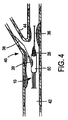
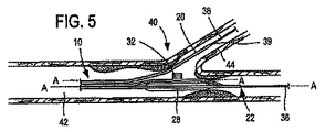
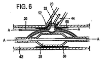
図3乃至図6を参照するに、本発明を実施する例示態様をここに説明することにする。図3と図5を参照するに、給送システムは通常血小板で出来た血管二分岐部40に隣接する例示人体内腔に対し図示してあり、給送システム10はその上にステントを装着しない状態で図示(図3と図5)してある。図4と図6は、その上にステント50を装着したステント給送システム10を示す。
With reference to FIGS. 3-6, exemplary embodiments for implementing the present invention will now be described. Referring to FIGS. 3 and 5, the delivery system is illustrated for an exemplary human body lumen adjacent to a
二分岐部40は、主血管42と分岐血管44とを含む。二分岐部40内に位置する例示障害物46は、主血管42と基端部分岐血管44に跨がるか或いは少なくとも一部遮っている。一般に、ステント給送システム10は種血管内に配置した第1の主誘導ワイヤを突き刺し、給送システムを治療部位へ誘導することができる。より詳しくは、第1の誘導ワイヤ36の基端を主誘導ワイヤ管腔部22の先端開口端へ突き刺し、給送システムを図3に示す二分岐部40又はその近傍の位置へ追尾させる。そこで、第2の誘導ワイヤ38(図5)を給送システムの基端からステント給送システム10内へ突き刺す。より詳しくは、第2の誘導ワイヤ38を側方外装20の開口基端37内へ突き刺し、図5に示した如く、側方外装20の開口先端39を介してそこから延出させることができる。さもなくば、第2の誘導ワイヤ38は側方外装内部に休止状態に係止でき、システムが二分岐部40近傍にあるときに、それを側方外装20から出して側方分岐血管44内へ前進させることができる。本発明原理になるシステムは、ワイヤ媒介システム或いは迅速交換システムに使用でき、それらのシステムには側方外装或いは主カテーテルの片側或いは両側での急速交換を含ませることができる。迅速交換は、2003年9月25日に公開されたVardi等に対する米国特許出願第2003/0181923号の一例示実施形態に記載されており、その内容は全て本願明細書に参照用に取り込むものとする。
The
一実施形態では、ステント給送システム10を二分岐部40近傍に配置し、先端16(図1)を側方分岐血管44(図3乃至図6)近傍に配置した状態で、第2の誘導ワイヤ38を側方外装20から側方分岐血管44内へ進入させる。次に、バルーン26の第1と第2の可膨張部は側方分岐血管44の開口に隣接配置し、これにより二分岐バルーン26の補助可膨張側方部32を側方分岐血管に整列配置させる。一つの例示実施形態では、整列配置はその内容全体を参照用に本願明細書に取り込むVardi等に対する米国特許第6,692,483号に記載されたマーカーを用いて達成される。第2の誘導ワイヤ38を側方分岐外装20内に残し、システム10の先端16を主血管42内に残す。第1の誘導ワイヤ36は第1の誘導ワイヤ管腔部22内に残し、さらに前進させて主分岐血管42内へ配置することができる。
In one embodiment, the second delivery with the
一旦システムを適切に配置すると、被加圧流体をバルーン26の第1と第2の可膨張部28,32へそれぞれ供給し、人体内腔を拡大してその上に装着したステントを拡張させる(図6)。好ましくは、可膨張部28がステント本体を拡張し、図6を参照してさらに詳しく説明する如く、可膨張部32がステントの側方(開口)と可膨張分岐構造を拡張する。可膨張部28,32を上記の如く膨張させた後、膨張管腔部34を介して膨張流体を排出することでバルーン26を収縮させる。これにより、可膨張部28,32は血管42からのアセンブリの引き抜きに備え圧潰させられるようになる。
Once the system is properly positioned, pressurized fluid is supplied to the first and second
ここで図4と図6を参照するに、一つの好適な実施形態がステント給送システム10とステント給送システムの先端16外部に装着した例示ステント50とをもって図示してある。ステント50は、例えば「二分岐血管用突出分岐部付きステント(Stent with Protruding Branch Portion for Bifurcated Vessels)」と題する米国特許第6,210,429号と同時係属米国特許出願第10/644,550号に記載されている如く分岐血管内へ伸長させる構成とした可伸長分岐部52を含む。第2の可膨張部32は外方拡張ステント要素すなわち分岐部52を展開させるよう構成し配置することができ、分岐部52に隣接配置するか或いはステント内の側方分岐アクセス開口内へ配置することができる。図6に示す如く、第1と第2の可膨張部28,32を膨張させたときに、それらは膨張管腔部の構造に応じて同時に或いは順次ステント50をして主血管42内で拡張させ、ステント50の分岐部52をして分岐血管44内へ押し込み、すなわち延出させる。バルーン26の膨張時に、第2の可膨張部32は分岐部52を分岐血管へ向け拡張延出させ、側方分岐動脈の入口或いは心門を開口し支持する。このことはバルーンが共通の膨張管腔部を共有するときに同時に生起し、個別膨張管腔部を用いた場合には順次生起し得る。二分岐バルーンは図示の如く描いたが、3以上の可膨張部すなわち3以上のバルーンを本発明と共に使用したり、図12乃至図14を参照して説明する如く単一のバルーンをここで使用することもできる。
Referring now to FIGS. 4 and 6, one preferred embodiment is illustrated with a
さらに、図1乃至図6に示した実施形態の第2の可膨張部32は第2の分岐部30上に中央配置して示したが、可膨張部32は第2の分岐部30の長さに沿う任意の所望位置に配置できることに留意されたい。例えば、一旦ステントを結合すると、それは好ましくはステントの中間1/3に沿うか或いは可伸長分岐構造に隣接する位置に対応するよう配置することができる。
Furthermore, although the second
例えば図5と図6に示すように、第1と第2の分岐部27,30は長手方向軸Aを有する。この長手方向軸は、互いにほぼ平行である。用語「ほぼ平行」には、人体内腔内への挿入や移送や展開期間中に遭遇する分岐部27,30或いは他の部品の撓みにより引き起こされる純粋な平行関係からのずれを包含する意図を込めてある。
For example, as shown in FIGS. 5 and 6, the first and
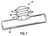
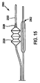
ここで図7を参照するに、蛇腹式特徴をここに例示実施形態を参照してより詳しく説明することにする。図7は、図1乃至図6に描いた二分岐バルーン26の可膨張側方部32の拡大図である。可膨張側方部32は、システムの長手方向軸から外方へ分岐血管内へ側方延出する構成としてある。図示の如く、可膨張側方部32は一連の流体接続セル60を含む点において概ね「蛇腹」形状を有する。蛇腹式セル60は、好ましくは幅狭端部62へ向け先細とした幅広中央部64を有する。かくして、輪郭を見たときに、膨張時にセル60は典型的な「平坦化」された六角形状を有する。しかしながら、この輪郭形状は不可欠ではない。例えば、セル60の輪郭により丸まった形状を持たせることもできる。さらに、蛇腹式構造33は、最大膨張時に個別セル60を統合させ、概ね管状の構造を得ることができるよう構成することもできる。収縮時、セルは以下にさらに詳しく説明する如く目立たない輪郭構造へ圧潰する。
Referring now to FIG. 7, the bellows feature will now be described in more detail with reference to an exemplary embodiment. FIG. 7 is an enlarged view of the
個別セル60は、狭幅端部62を介して流体接続してある。かくして、バルーン26の可膨張側方部32の一番目のセル60に進入する流体は可膨張側方部32からなる一連のセル60内の続くセル60へ流れ、一番目のセル60から最終セル60まで主膨張軸を作成する。こうして、可膨張側方部32は主膨張の軸に垂直な半径方向よりも主膨張軸に沿ってより大きな長さへ膨張させることができる。非膨張状態と同じく、バルーンはほぼ平坦、例えば平坦な可撓性円盤形状をなし、膨張構造においてバルーン長は主膨張軸に沿って著しく増大する。対照的に、例えば主バルーン28は膨張時にほぼ不変のままに止まる比較的固定された長手方向長さを有する。
The individual cell 60 is fluidly connected through a
主膨張軸に沿って見たときに、セル60は好ましくは円形である。しかしながら、任意の形状を用いることができる。例えば、これに限定はされないが、セル60は楕円形や四角形や六角形や八角形とすることができる。さらに、連続するセル60を同じ大きさとする必要はない。例えば、連続セル60は先行セル60から寸法を減少或いは増大させ、先細又は先太の可膨張側方部32を得ることもできる。
Cell 60 is preferably circular when viewed along the main expansion axis. However, any shape can be used. For example, but not limited to this, the cell 60 may be an ellipse, a rectangle, a hexagon, or an octagon. Furthermore, the continuous cells 60 need not have the same size. For example, the continuous cell 60 may be reduced or increased in size from the preceding cell 60 to obtain a tapered or tapered
補助可膨張側方部32の構成要素は、当業者には即明らかな如く、適当な大きさとすることができる。蛇腹式構造33には、適当な膨張セル径とコネクタ径とを持たせることができる。その直径は、当業者に公知の様々な要因に従って可変することができる。さらに、補助可膨張側方部32は特定用途向けに決定された任意数のセル35で構成することができる。加えて、第2の可膨張部32の膨張がステント50の分岐部52を側方分岐血管44へ展開させる力と構造を生み出す。従って、第2の可膨張部32は所望の如く半径方向の膨張を制御すなわち制限しつつステントの分岐部52を展開すなわち押し出すことができる。
The components of the auxiliary
前記し図示した分岐血管可膨張部32は、蛇腹式特徴からなる一実施形態を含み、ここに他の実施形態を図示し以下に説明する。しかしながら、可膨張部32の蛇腹式構造には本発明原理に従い異なる形状と寸法と構造を含ませることができる。例えば、蛇腹式特徴は「ステント給送システム(Stent Delivery Systems)」と題する米国仮特許出願第60/518,870号に開示された実施形態と組み合わせることができる。また、図1乃至図7を参照して上記した蛇腹式原理は、本願明細書に記載する他の実施形態に当てはまるものである。
The bifurcated vascular
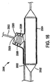
図8は、単独で包含するか或いは例えば前述した種のステント給送システム内へ組み込むことで分岐動脈の治療にも使用する本発明の代替実施形態を示す。図8の実施形態に描かれたバルーンは、前記した実施形態と同様の仕方で機能する「脱漏」蛇腹式バルーン構造と呼ぶことができる。脱漏蛇腹式バルーン構造は、非膨張構造において概ね筒状を有し、膨張状態或いは構造において分岐動脈へ向けバルーンの長手方向軸に対し外方へ膨張する概ね蛇腹形状の付属物の付いた概略筒状を有することを特徴とするものである。この突起は、例えば脱漏部や隆起部や突出部や伸長部と呼ぶことができる。ここに例示したバルーンと蛇腹式脱漏部の特定の形状と大きさと構造は例示であり、明示的に図示或いは説明したものから修正することができる。可膨張脱漏部や隆起部や突出部や伸長部は、1〜4mm等の適当な長さに亙り側方分岐の入口(図3の例えば44参照)へ向け可膨張とすることができる。 FIG. 8 shows an alternative embodiment of the present invention that may be used alone or for the treatment of bifurcated arteries, for example, by being incorporated into a stent delivery system of the type described above. The balloon depicted in the embodiment of FIG. 8 can be referred to as a “leaky” bellows-type balloon structure that functions in a manner similar to the previously described embodiment. The leak-free bellows-type balloon structure has a generally cylindrical shape in a non-inflatable structure, and a general cylinder with a generally bellows-shaped appendage that expands outwardly with respect to the longitudinal axis of the balloon toward the branch artery in the inflated state or structure. It is characterized by having a shape. This protrusion can be called, for example, a leakage portion, a raised portion, a protruding portion, or an elongated portion. The specific shape, size, and structure of the balloon and bellows-type leakage portion illustrated here are examples and can be modified from those explicitly shown or described. The inflatable leaking part, the raised part, the protruding part, and the extending part can be inflated to an appropriate length such as 1 to 4 mm toward the side branch inlet (see, for example, 44 in FIG. 3).
図8に描かれたバルーンの実施形態は、先に例示した実施形態(例えば、図1乃至図7参照)に関連付けて説明したものと同様の仕方で用いることができる。図8に描かれた実施形態については、ここに描かれた脱漏部蛇腹式バルーン構造は単独使用するか、或いは二分岐バルーン全体(例えば図1乃至図7の26)と置き換えるか、或いは本発明原理に従って必要とされる幾つかの修正をもった二分岐バルーン(例えば、32)の一部とし得ることを理解されたい。 The balloon embodiment depicted in FIG. 8 can be used in a manner similar to that described in connection with the previously illustrated embodiments (see, eg, FIGS. 1-7). For the embodiment depicted in FIG. 8, the leak-through bellows-type balloon structure depicted herein can be used alone or replaced with the entire bifurcated balloon (eg, 26 in FIGS. 1-7) or the present invention. It should be understood that it may be part of a bifurcated balloon (eg 32) with some modifications required according to the principle.
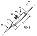
脱漏蛇腹式バルーンカテーテル526の例示実施形態が、図8に例示してある。例示実施形態では、脱漏バルーンカテーテル526は細長い可膨張部528と蛇腹式脱漏部か隆起部か突出部か伸長部532とを備えるバルーン527で構成してある。図8の実施形態では、バルーンカテーテル526はバルーン527を膨張させる圧力の連通に役立ち得る管腔部534をさらに含み、誘導ワイヤ等のための通路を備える。
An exemplary embodiment of a leak-free bellows type
バルーン527の特定の構造と寸法は、幾つかの要因に従って変えることができる。例示目的にだけではあるが、バルーン527の様々な部品の幾つかの適切な、ただしこれに限定はされない寸法をここに記載することにする。バルーン527には、約4〜100mmである長さ寸法L1を持たせることができる。バルーンには、約1〜10mm台である外径OD1を持たせることができる。
The particular structure and dimensions of
図8に例示した実施形態の蛇腹式脱漏部532は脱漏部バルーン527上に中央配置して図示したが、脱漏部532はバルーンの長さに沿う任意の所望位置に配置できることに留意されたい。例えば、一旦ステントに結合すると、それは好ましくはステントの中間1/3に沿い及び/又はステントの可伸長分岐構造に隣接する位置に対応するよう配置することができる。
It should be noted that although the bellows
バルーン527は、本願明細書に先に開示したもの等の任意の適当な材料にて構成することができる。加えて、本願明細書に記載する他の任意の実施形態だけでなくバルーン527もまた、複合材料にて構成することができる。適当な材料は、ウレタンやシリコンやナイロンやラテックスや(エラストマ性)ポリエチレン・ハイトレル・ペバックス・ポリアリルエチルケトンやポリオキシメチレンやポリアミドやポリエステル熱可塑性ポリエーテルエチルケトンやポリプロピレン(準剛体)等のエラストマ性の非可撓性材料の組み合わせを含む。バルーン526は、上記に開示した材料にKevlar(アラミド繊維)や絹や木綿や羊毛等の織布材料を組み合わせることで構成することもできる。これは、所望の蛇腹式脱漏バルーン形状を有するロッド上に織物材料を巻き付けるか織り込むことで達成することができる。複合材の高分子成分をそこでロッド上に押し出し加工するか或いは浸漬被覆する。この複合材構造は続いて硬化させるか、加熱処理するか、或いは互いに溶融接着させる。次にロッドを取り去ると、残る形状が蛇腹脱漏部バルーン527を構成する。さもなくば、これは上記材料に蛇腹式バルーン部にではなく主バルーン部にだけ織布材料を組み合わせ、それによって適用時に如何なる工程であろうともエラストマ性のすなわち例えばポリウレタンだけで蛇腹式バルーン部を形成することにより達成することができる。
蛇腹式脱漏部532は、被成形カラーを用いるか或いはバルーン表面に対象物を接着により取り付けるか或いは脱漏部を創成するよう接着剤の小山を用いることにより、従前のバルーンに対し付属物を追加することで配設することができる。
The bellows-type leak-off
バルーン527は3個の小型バルーンを成形し、それらを縦列的に取り付け、中央のバルーンが所望形状の蛇腹式脱漏部を構成するよう構成できる。これらのバルーンは、共通の膨張ポートを共有しよう。バルーンを膨張させると、バルーン中心は所望の態様で膨張し、蛇腹式脱漏部を形成する。
The
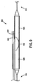
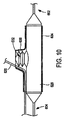
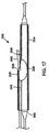
図9は、その先端部と基端部だけを図示したステント給送システム600内のバルーン527を示す。システム600は、非膨張状態にて図示してある。先端は602で示され、基端は604で示される。システム600は、概ね前記した種のバルーン526と側方外装620と二分岐ステント624とを含む。ステントは、例示用に概略的に細部を略して描いてある。側方外装620は、ステント624内の側方分岐アクセス開口を介して伸びている。この図では、非膨張蛇腹式脱漏部が参照符号532にて図示してある。非膨張時すなわち圧潰時に、蛇腹式脱漏部532はほぼ平坦な構造、例えば平坦な可撓性円盤形状をなす。図示の如く、非膨張蛇腹式脱漏部532は折り畳み等によりバルーン526の側部に対し配置してある。しかしながら、非膨張蛇腹式脱漏部532をこうして折り畳む必要はない。例えば非膨張蛇腹式脱漏部532はバルーン527の頂部全体に折り畳むことができる。事実、脱漏部532を膨張させ、特に膨張させて分岐部626を展開させることができる限り、任意の折り畳み技法を用いることができる。図10は、蛇腹式脱漏部532を膨張させてステント624の分岐部626を分岐血管(図示せず)内へ外方展開させた膨張状態にあるシステム600を示す。
FIG. 9 shows a
図示の如く、本実施形態の蛇腹式脱漏部532と先の実施形態の第2の可膨張部32はこれらの個別実施形態の細長い可膨張部528,28の長手方向軸にほぼ垂直な方向に膨張させて図示してある。しかしながら、蛇腹式脱漏部532と第2の可膨張部32は治療対象である特定構造の二分岐血管が必要とする細長い可膨張部528,28に対し任意の角度で膨張するよう製造できる。加えて、これらの実施形態では、蛇腹式構造33の膨張軸は蛇腹式構造33へ空気を供給する膨張管腔部の軸に対し概ね所定角度をなす。
As shown, the bellows-
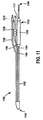
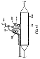
ここで図11と図12を参照するに、ステント給送システム1190の代替実施形態が図示してある。ステント給送システム1190は、基端1194から先端1196へ伸びる細長い主カテーテル軸1192を備える。先端1196には、主血管分岐部1198と側方分岐外装1100とを備える二つの分岐部を含ませることができる。主血管分岐部1198自体は、二つの分岐、すなわちバルーン1102を含めることのできる第1の分岐1104と蛇腹式分岐部1106とを含めることができる。バルーン1102には、主血管分岐部1198の第1の分岐部1104に沿って伸びる細長い可膨張部1108を含めることができる。
Referring now to FIGS. 11 and 12, an alternative embodiment of the
蛇腹式分岐部1106は、主血管分岐部1198の間を側方分岐外装1100の先端近傍へ伸ばすことができる。蛇腹式分岐部1106には、概ね軸方向の可膨張部1109、特に蛇腹式バルーンを含めることができる。一般に、可膨張部1109は膨張時に一軸、例えばその長手方向軸1111に沿って伸び、すなわち伸長するよう構成し設計してある。本発明の好適な実施形態では、軸方向可膨張部1109の先端は側方外装1100へ摺動可能に取り付けてあり、一方で基端は主血管分岐部1198へ固着することができる。部分1109は、例えば可撓性管を含め本発明原理に従い任意の構造により摺動可能に取り付けることができる。
The bellows type branching
摺動可能な一つの取り付け方法では、軸方向の可膨張部1109の先端を側方外装1100外部に摺動自在に受け入れる管状部材1110に固定的に取り付けることができる。好適な実施形態では、軸方向の可膨張部1109は概ね蛇腹と同様の形状としかつ/又は折り畳み、膨張時に可膨張部1109はその長手方向軸1111に沿い軸方向へ展開すなわち膨張させる。こうして、可膨張部1109の先端は側方外装1100沿いに先端方向へ摺動する。
In one slidable attachment method, the distal end of the
手術時、ステント2136を給送システム1190上に装着して血管分岐部へ給送したときに、ステント2136の外方展開可能な要素すなわち分岐部2138は都合よくは軸方向可膨張部1109(図12)により展開させることができる。可膨張部1109は非膨張構造のステント2136内に配置してあり、その軸、例えばその長手方向軸に沿って分岐血管内へ可膨張としてある。可膨張部1109は側方外装1100沿いに先端方向へ摺動するため、ステント2136の分岐部2138を側方分岐血管内へより効果的に展開させることのできる側方外装1100の方向に軸力を生ずる。生じた軸力は、半径方向の拡張を所期の如くに制御すなわち制限しつつステントの分岐部2138を展開すなわち押し出すことができる。その結果、ステント2136は側方分岐血管内の病巣をより効果的に治療できる分岐部を持たせて設計することができる。例えば、一部のステント2136設計では、ステント2136の可伸長分岐部2138はこの給送システム構成を用いて分岐部内へさらに拡張させることができる。
During surgery, when the
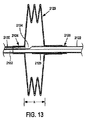
図13と図14A,14Bを参照するに、蛇腹式すなわち軸方向に可膨張のバルーン2120の代替実施形態が図示してある。バルーン2120は、カテーテル或いは外装2122沿いに同軸的に膨張する。外装2122は、バルーン2120を膨張させる膨張管腔部2130と、誘導ワイヤを受け入れる誘導ワイヤ管腔部2132とを含む。膨張管腔部2130は、バルーン吸入口2134を介してバルーン2120に流体連通させてある。バルーン2120の基端2124は外装2122へ固定的に取り付けてあり、バルーン2120の先端2126は外装2122の外面へ摺動可能に受け入れる管状部材2128へ固定的に取り付けてある。管状部材2128は、可撓性管とすることができる。管状部材2128は、好ましくはバルーン材料へ取り付けるに十分でかつバルーン2120の膨張時にバルーン2120内へ伸長して気液密の封止を作成するに十分な長さを有する。特に、管状部材2128は、膨張時に外装2122に沿って摺動可能としてあり、しかも膨張時にバルーン内部の外装2122の端部は流体の気液密の封止を作成するのに十分な量でもって外装2122へ押圧される。手術に際し、膨張時に先端2126を外装2122沿いに摺動可能とし、管状部材2128によりバルーン2120を図13に示す膨張量xからさらに図14Aに示す膨張量yへ、さらに図14Bに示す膨張量zへもっと膨張させ、ただしx<y<zである。図示していない代替実施形態では、基端と先端2124,2126は本発明原理に従い先端から伸びる外装と基端から伸びる外装とに固定的に固着することもできる。
Referring to FIGS. 13 and 14A, 14B, an alternative embodiment of a bellows or axially
図13と図14A,14Bの実施形態は単独で、或いは本願明細書に開示した他の実施形態と組み合わせて用いることができる。例えば、外装2122(図13と図14A,14B)はステント給送システムの一部とすることができる。図15乃至図17に示した如く、ステント給送システム2300には図13と図14A,14Bを参照して説明した種の側方外装2322と主バルーンカテーテル2302とを含めることができる。側方外装2322は、前記した管状部材2328を有する蛇腹式バルーン2320を含む。図16は膨張状態にあるシステム2300に装着したステント2324を示し、一方で図17は非膨張状態のシステム2300に装着したステント2324を示す。分岐部2326を有するステント2324を給送システム上に装着し、血管分岐部へ給送すると、外装2322はバルーン2320が分岐部の内部に隣接配置された状態でステント2324の側方アクセス孔を介して伸長させることができる。図13と図14A,14Bに示す実施形態の如く、蛇腹式バルーン2320はステント2324の分岐部2326の展開を可能にする仕方で折り畳むことができる。膨張時、外装2322に沿って先端方向に先端側へ摺動して側方外装の軸に沿う軸力を生成する管状部材2328により、バルーン2320は軸方向に膨張する。生じた軸力は、ステント2324の分岐部2326を分岐血管内へ十分な長さ、しかも分岐部2326を半径方向へ不必要に膨張させずに伸長すなわち押し出すことができる。その結果、ステント2324は分岐血管内の病巣の治療により効果的に用いることのできる分岐部2326を有する。例えば、一部のステント設計では、ステント2324の可伸長分岐部2326はこの給送システム構成を用いて分岐内へさらに伸長させることができる。
The embodiment of FIGS. 13 and 14A, 14B can be used alone or in combination with other embodiments disclosed herein. For example, the sheath 2122 (FIGS. 13 and 14A, 14B) can be part of a stent delivery system. As shown in FIGS. 15-17, the
図11乃至図17の実施形態の代替実施形態は、側方外装を備える蛇腹式バルーンに結合し、膨張時に蛇腹式バルーンが側方分岐血管内へ側方外装に追従するようにできる。 An alternative embodiment of the embodiment of FIGS. 11-17 can be coupled to a bellows-type balloon with a side sheath so that, when inflated, the bellows-type balloon follows the side sheath into the side branch vessel.
本発明は、単一の蛇腹式バルーンと共に使用するよう説明してきたが、例えば「カテーテルバルーンシステム及び方法(Catheter Balloon Systems and Methods)」と題する同時係属米国特許出願第10/834,066号に記載されている如く、1以上の蛇腹式バルーンの使用は熟慮してある。 The present invention has been described for use with a single bellows type balloon, but is described, for example, in co-pending US patent application Ser. No. 10 / 834,066 entitled “Catheter Balloon Systems and Methods”. As noted, the use of one or more bellows balloons is contemplated.
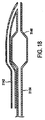
図18に示す代替実施形態では、第1の誘導ワイヤ管腔部3142は第1の可膨張部3148内を挿通させることはできない。例えば、管腔部はバルーン外部に固定するか或いは誘導ワイヤが挿通する複数の折り畳み部をもってバルーンを形成することができる。さもなくば、誘導ワイヤ(図示せず)はバルーンの折り畳み部を挿通させることができる。本実施形態では、誘導ワイヤ管腔部3142は膨張管腔部3154とは別個にしてある。好適な実施形態では、誘導ワイヤ管腔部3142は膨張管腔部3154に比べ短縮すなわちより短い長さを有し、それによって誘導ワイヤが挿通するより少ない管腔部を備える。管腔部3142,3154の先端は好ましくは接着等により給送システムの最先端にて互いに取り付けてあり、誘導ワイヤの基端は膨張管腔部へ接続してある。かくして、このステント給送実施形態は「ワイヤ媒介」システムともならない(誘導ワイヤ管腔部は給送システムの全長に渡って膨張管腔部内部には止まらない)。それにも拘わらず、膨張した管腔部3154に比し誘導ワイヤ管腔部3142の短縮されたすなわちより短かい長さにより、例えばそこを介する誘導ワイヤの素早い挿入と除去が可能になる。この特徴は使用するバルーンの数に関係なく、或いは給送システムが側方外装を用いるかどうかに関係なく、給送システムに使用できる。例えば、これは単独で或いは本願明細書に記載した他の実施形態と組み合わせて使用することもできる。
In the alternative embodiment shown in FIG. 18, the first
本発明はその特定の実施形態及びその実施例と併せ説明してきたが、本開示を読むことで多くの代替例や修正例や変形例が当業者には明らかとなろうことは明白である。従って、添付特許請求の範囲に趣旨ならびに広義の範囲に含まれるこの種代替例や修正例や変形例を全て包含することを意図するものである。さらに、各実施形態の特徴は全体又は一部を他の実施形態に用いることができる。 While the invention has been described in conjunction with specific embodiments and examples thereof, it is evident that many alternatives, modifications and variations will become apparent to those skilled in the art upon reading this disclosure. Accordingly, it is intended to cover all such alternatives, modifications and variations that fall within the spirit and broad scope of the appended claims. Furthermore, the features of each embodiment can be used in whole or in part for other embodiments.
10 ステント給送システム
12 カテーテル軸
14 基端
16 先端
18 主血管分岐部
20 側方分岐外装
22 誘導ワイヤ管腔部
26 バルーン
27 第1の分岐部
28 第1の可膨張部
30 第2の分岐部
32 第2の可膨張部
33 蛇腹式構造
34 膨張管腔部
35,60 セル
40 二分岐部
42 主血管
44 分岐血管
50 ステント
52 分岐部
532 脱漏部
DESCRIPTION OF
Claims (10)
基端と先端を有する細長いカテーテルと、
前記カテーテルの先端に結合したバルーンで、二分岐部の主血管を治療する主血管バルーンと二分岐部の分岐血管を治療する分岐血管バルーンとを含む前記バルーンとを備え、
前記分岐血管バルーンは非膨張構造と膨張構造との間で可膨張としてあり、前記非膨張構造において前記分岐血管バルーンを前記主血管バルーンに隣接させてほぼ平坦とし、前記膨張構造において前記分岐血管バルーンをほぼ管状とした、ことを特徴とする二分岐血管に用いるカテーテルアセンブリ。 A catheter assembly for use in a bifurcated vessel,
An elongated catheter having a proximal end and a distal end;
A balloon coupled to the distal end of the catheter, comprising:
The branch vessel balloon is inflatable between a non-inflatable structure and an inflatable structure, and the branch vessel balloon is made substantially flat adjacent to the main vessel balloon in the non-inflated structure, and the branch vessel balloon in the inflated structure. A catheter assembly for use in a bifurcated blood vessel, characterized in that the tube is substantially tubular.
前記分岐血管バルーン内部に流体連通する第1の膨張管腔部と前記主血管バルーン内部に流体連通する第2の膨張管腔部とを備える、請求項1記載の二分岐血管に用いるカテーテルアセンブリ。 The catheter includes an inflation lumen, the balloon has an interior in fluid communication with the inflation lumen, the inflation lumen further comprising:
The catheter assembly used for a bifurcated blood vessel according to claim 1, comprising a first inflation lumen portion in fluid communication with the inside of the branch vessel balloon and a second inflation lumen portion in fluid communication with the inside of the main vessel balloon.
Applications Claiming Priority (2)
| Application Number | Priority Date | Filing Date | Title |
|---|---|---|---|
| US10/985,005 US7344557B2 (en) | 2003-11-12 | 2004-11-10 | Catheter balloon systems and methods |
| PCT/US2005/040696 WO2006053106A1 (en) | 2004-11-10 | 2005-11-09 | Catheter balloon systems and methods |
Publications (1)
| Publication Number | Publication Date |
|---|---|
| JP2008519612A true JP2008519612A (en) | 2008-06-12 |
Family
ID=36088509
Family Applications (1)
| Application Number | Title | Priority Date | Filing Date |
|---|---|---|---|
| JP2007540203A Withdrawn JP2008519612A (en) | 2004-11-10 | 2005-11-09 | Catheter balloon system and method |
Country Status (5)
| Country | Link |
|---|---|
| US (2) | US7344557B2 (en) |
| EP (1) | EP1816981A1 (en) |
| JP (1) | JP2008519612A (en) |
| CA (1) | CA2586940A1 (en) |
| WO (1) | WO2006053106A1 (en) |
Cited By (3)
| Publication number | Priority date | Publication date | Assignee | Title |
|---|---|---|---|---|
| JP2010501249A (en) * | 2006-08-23 | 2010-01-21 | ボストン サイエンティフィック リミテッド | Catheter with auxiliary balloon |
| JP2011524197A (en) * | 2008-06-13 | 2011-09-01 | ボストン サイエンティフィック サイムド,インコーポレイテッド | Bifurcated catheter assembly comprising a laterally attached side balloon |
| JP2011525847A (en) * | 2008-06-27 | 2011-09-29 | ボストン サイエンティフィック サイムド,インコーポレイテッド | Apparatus and method for folding a balloon |
Families Citing this family (64)
| Publication number | Priority date | Publication date | Assignee | Title |
|---|---|---|---|---|
| US7147661B2 (en) | 2001-12-20 | 2006-12-12 | Boston Scientific Santa Rosa Corp. | Radially expandable stent |
| US20060253480A1 (en) * | 2002-04-06 | 2006-11-09 | Staples Peter E | Collaborative design process for a design team, outside suppliers, and outside manufacturers |
| US8920432B2 (en) | 2002-09-24 | 2014-12-30 | Medtronic, Inc. | Lead delivery device and method |
| US9636499B2 (en) | 2002-09-24 | 2017-05-02 | Medtronic, Inc. | Lead delivery device and method |
| US9849279B2 (en) * | 2008-06-27 | 2017-12-26 | Medtronic, Inc. | Lead delivery device and method |
| US9480839B2 (en) | 2002-09-24 | 2016-11-01 | Medtronic, Inc. | Lead delivery device and method |
| AU2004284893A1 (en) * | 2003-11-03 | 2005-05-12 | B-Balloon Ltd. | Treatment of vascular bifurcations |
| US7344557B2 (en) * | 2003-11-12 | 2008-03-18 | Advanced Stent Technologies, Inc. | Catheter balloon systems and methods |
| US7780715B2 (en) | 2004-03-04 | 2010-08-24 | Y Med, Inc. | Vessel treatment devices |
| US7766951B2 (en) | 2004-03-04 | 2010-08-03 | Y Med, Inc. | Vessel treatment devices |
| US9050437B2 (en) | 2004-03-04 | 2015-06-09 | YMED, Inc. | Positioning device for ostial lesions |
| ATE508714T1 (en) * | 2005-01-10 | 2011-05-15 | Trireme Medical Inc | STENT WITH SELF-EXPANDABLE AREA |
| US9101500B2 (en) * | 2005-01-10 | 2015-08-11 | Trireme Medical, Inc. | Stent with self-deployable portion having wings of different lengths |
| US7922754B2 (en) | 2005-04-18 | 2011-04-12 | Trireme Medical, Inc. | Apparatus and methods for delivering prostheses to luminal bifurcations |
| US7862601B2 (en) * | 2005-05-23 | 2011-01-04 | Incept Llc | Apparatus and methods for delivering a stent into an ostium |
| US8608789B2 (en) | 2005-05-24 | 2013-12-17 | Trireme Medical, Inc. | Delivery system for bifurcation stents |
| US9439662B2 (en) | 2005-07-05 | 2016-09-13 | Angioslide Ltd. | Balloon catheter |
| US8556851B2 (en) * | 2005-07-05 | 2013-10-15 | Angioslide Ltd. | Balloon catheter |
| US20070067023A1 (en) * | 2005-09-22 | 2007-03-22 | Boston Scientific Scimed, Inc. | Tether guided stent side branch |
| US7776079B2 (en) * | 2005-10-31 | 2010-08-17 | Boston Scientific Scimed, Inc. | Conical balloon for deployment into side branch |
| US20070270933A1 (en) * | 2006-03-09 | 2007-11-22 | Abbott Laboratories | Stent having contoured proximal end |
| US8167929B2 (en) * | 2006-03-09 | 2012-05-01 | Abbott Laboratories | System and method for delivering a stent to a bifurcated vessel |
| US7901378B2 (en) | 2006-05-11 | 2011-03-08 | Y-Med, Inc. | Systems and methods for treating a vessel using focused force |
| US8486025B2 (en) | 2006-05-11 | 2013-07-16 | Ronald J. Solar | Systems and methods for treating a vessel using focused force |
| US8454681B2 (en) * | 2006-09-13 | 2013-06-04 | Boston Scientific Scimed, Inc. | Bifurcation delivery systems and methods |
| US8608790B2 (en) * | 2006-10-06 | 2013-12-17 | Boston Scientific Scimed, Inc. | Bifurcation catheter and method |
| US7871396B2 (en) * | 2006-10-30 | 2011-01-18 | Boston Scientific Scimed, Inc. | Bifurcation catheter assembly and method |
| US20080147174A1 (en) * | 2006-12-11 | 2008-06-19 | Trireme Medical, Inc. | Apparatus and method of using markers to position stents in bifurcations |
| US8343181B2 (en) * | 2007-03-01 | 2013-01-01 | Medtronic Vascular, Inc. | Method and apparatus for treating stenoses at bifurcated regions |
| US8647376B2 (en) | 2007-03-30 | 2014-02-11 | Boston Scientific Scimed, Inc. | Balloon fold design for deployment of bifurcated stent petal architecture |
| US20080255653A1 (en) * | 2007-04-13 | 2008-10-16 | Medtronic Vascular, Inc. | Multiple Stent Delivery System and Method |
| US8486134B2 (en) * | 2007-08-01 | 2013-07-16 | Boston Scientific Scimed, Inc. | Bifurcation treatment system and methods |
| US7867435B2 (en) * | 2008-03-21 | 2011-01-11 | Boston Scientific Scimed, Inc. | Manufacture of inflatable member for bifurcation catheter assembly |
| US20090287148A1 (en) * | 2008-05-15 | 2009-11-19 | Martin Daryl L | Joined Inflation Portions for Bifurcation Catheter |
| US8932340B2 (en) | 2008-05-29 | 2015-01-13 | Boston Scientific Scimed, Inc. | Bifurcated stent and delivery system |
| JP5662310B2 (en) * | 2008-06-05 | 2015-01-28 | ボストン サイエンティフィック サイムド,インコーポレイテッドBoston Scientific Scimed,Inc. | Shrinkable branch device and method of manufacturing the same |
| WO2009149405A1 (en) * | 2008-06-05 | 2009-12-10 | Boston Scientific Scimed, Inc. | Balloon bifurcated lumen treatment |
| US8308793B2 (en) * | 2008-06-10 | 2012-11-13 | Boston Scientific Scimed, Inc. | Bifurcation catheter assembly with dynamic side branch lumen |
| US9775989B2 (en) | 2008-06-27 | 2017-10-03 | Medtronic, Inc. | Lead delivery device and method |
| US11931523B2 (en) | 2008-06-27 | 2024-03-19 | Medtronic, Inc. | Lead delivery device and method |
| US9775990B2 (en) | 2008-06-27 | 2017-10-03 | Medtronic, Inc. | Lead delivery device and method |
| WO2010001404A1 (en) | 2008-07-02 | 2010-01-07 | Angioslide Ltd. | Balloon catheter system and methods of use thereof |
| US8333794B2 (en) * | 2008-07-25 | 2012-12-18 | Boston Scientific Scimed, Inc. | Side balloon identifiers and methods for radial and axial alignment in a catheter assembly |
| US8945198B2 (en) * | 2008-07-31 | 2015-02-03 | Boston Scientific Scimed, Inc. | Locating side catheter branch relative to inflation portion |
| US8152840B2 (en) * | 2008-07-31 | 2012-04-10 | Boston Scientific Scimed, Inc. | Bifurcation catheter assembly and methods |
| US8163123B2 (en) * | 2008-07-31 | 2012-04-24 | Boston Scientific Scimed, Inc. | Bifurcation catheter dual balloon bond and methods |
| US8187313B2 (en) * | 2008-08-01 | 2012-05-29 | Boston Scientific Scimed, Inc. | Bifurcation catheter assembly side catheter branch construction and methods |
| US8133199B2 (en) | 2008-08-27 | 2012-03-13 | Boston Scientific Scimed, Inc. | Electroactive polymer activation system for a medical device |
| WO2010096708A1 (en) * | 2009-02-20 | 2010-08-26 | Boston Scientific Scimed, Inc. | Balloon catheter for placemnt of a stent in a bifurcated vessel |
| US20100217374A1 (en) * | 2009-02-20 | 2010-08-26 | Boston Scientific Scimed, Inc. | Torqueable Balloon Catheter |
| WO2010096570A2 (en) * | 2009-02-23 | 2010-08-26 | John To | Stent strut appositioner |
| US20110077730A1 (en) * | 2009-09-30 | 2011-03-31 | Fenster Michael S | Bifurcated balloon stent |
| WO2011080731A1 (en) * | 2010-01-03 | 2011-07-07 | Angioslide Ltd. | Corrugated balloon catheter and methods of use thereof |
| US9675780B2 (en) | 2010-01-19 | 2017-06-13 | Angioslide Ltd. | Balloon catheter system and methods of making and use thereof |
| US9402754B2 (en) | 2010-05-18 | 2016-08-02 | Abbott Cardiovascular Systems, Inc. | Expandable endoprostheses, systems, and methods for treating a bifurcated lumen |
| US8998936B2 (en) | 2011-06-30 | 2015-04-07 | The Spectranetics Corporation | Reentry catheter and method thereof |
| US9814862B2 (en) | 2011-06-30 | 2017-11-14 | The Spectranetics Corporation | Reentry catheter and method thereof |
| US8956376B2 (en) | 2011-06-30 | 2015-02-17 | The Spectranetics Corporation | Reentry catheter and method thereof |
| CN105025968A (en) | 2012-12-04 | 2015-11-04 | 安乔斯里德公司 | Balloon catheters and methods of use thereof |
| US9737426B2 (en) * | 2013-03-15 | 2017-08-22 | Altura Medical, Inc. | Endograft device delivery systems and associated methods |
| DE102013104029A1 (en) * | 2013-04-22 | 2014-10-23 | Innora Gmbh | balloon catheter |
| US10350395B2 (en) * | 2017-06-23 | 2019-07-16 | Cook Medical Technologies Llc | Introducer for lumen support or dilation |
| CN110547897B (en) * | 2019-09-04 | 2021-04-23 | 中国人民解放军总医院 | Vascular stent device |
| JP2025519611A (en) * | 2022-06-10 | 2025-06-26 | エンドロジックス エルエルシー | Balloon expandable bifurcated stent graft and method of use |
Family Cites Families (353)
| Publication number | Priority date | Publication date | Assignee | Title |
|---|---|---|---|---|
| US1596754A (en) | 1923-10-30 | 1926-08-17 | Judson D Moschelle | Reenforced tubing |
| US3657744A (en) * | 1970-05-08 | 1972-04-25 | Univ Minnesota | Method for fixing prosthetic implants in a living body |
| US3872893A (en) * | 1972-05-01 | 1975-03-25 | Fred T Roberts & Company | Self-reinforced plastic hose and method for molding same |
| IN144765B (en) | 1975-02-12 | 1978-07-01 | Rasmussen O B | |
| US4140126A (en) * | 1977-02-18 | 1979-02-20 | Choudhury M Hasan | Method for performing aneurysm repair |
| US4309994A (en) * | 1980-02-25 | 1982-01-12 | Grunwald Ronald P | Cardiovascular cannula |
| US4413989A (en) | 1980-09-08 | 1983-11-08 | Angiomedics Corporation | Expandable occlusion apparatus |
| US4410476A (en) | 1980-10-20 | 1983-10-18 | The United States Of America As Represented By The Secretary Of The Navy | Method for making radially compliant line array hose |
| JPS6010740B2 (en) | 1981-05-07 | 1985-03-19 | 宏司 井上 | Endotracheal tube for unilateral lung ventilation |
| US4946464A (en) | 1981-07-22 | 1990-08-07 | Pevsner Paul H | Method of manufacturing miniature balloon catheter and product thereof |
| US4479497A (en) * | 1982-11-12 | 1984-10-30 | Thomas J. Fogarty | Double lumen dilatation catheter |
| US4503569A (en) * | 1983-03-03 | 1985-03-12 | Dotter Charles T | Transluminally placed expandable graft prosthesis |
| US4939240A (en) * | 1983-03-04 | 1990-07-03 | Health Research, Inc. | Monoclonal antibodies to human breast carcinoma cells and their use in diagnosis and therapy |
| CA1194662A (en) | 1983-07-12 | 1985-10-08 | Lupke, Manfred A. A. | Producing double-walled helically wound thermoplastic pipe |
| US4552554A (en) | 1984-06-25 | 1985-11-12 | Medi-Tech Incorporated | Introducing catheter |
| WO1986002845A1 (en) | 1984-11-15 | 1986-05-22 | Stefano Nazari | Device for selective bronchial intubation and separate lung ventilation |
| US4733665C2 (en) * | 1985-11-07 | 2002-01-29 | Expandable Grafts Partnership | Expandable intraluminal graft and method and apparatus for implanting an expandable intraluminal graft |
| US5102417A (en) | 1985-11-07 | 1992-04-07 | Expandable Grafts Partnership | Expandable intraluminal graft, and method and apparatus for implanting an expandable intraluminal graft |
| US4681570A (en) | 1985-12-26 | 1987-07-21 | Dalton Michael J | Peritoneal catheter |
| US5000185A (en) * | 1986-02-28 | 1991-03-19 | Cardiovascular Imaging Systems, Inc. | Method for intravascular two-dimensional ultrasonography and recanalization |
| US5350395A (en) | 1986-04-15 | 1994-09-27 | Yock Paul G | Angioplasty apparatus facilitating rapid exchanges |
| US4964850A (en) | 1986-05-07 | 1990-10-23 | Vincent Bouton | Method for treating trans-nasal sinus afflictions using a double t-shaped trans-nasal aerator |
| US4759748A (en) | 1986-06-30 | 1988-07-26 | Raychem Corporation | Guiding catheter |
| US4731055A (en) * | 1986-08-25 | 1988-03-15 | Becton, Dickinson And Company | Blood flow conduit |
| JPH0763489B2 (en) | 1986-10-31 | 1995-07-12 | 宇部興産株式会社 | Medical tube |
| US4762128A (en) | 1986-12-09 | 1988-08-09 | Advanced Surgical Intervention, Inc. | Method and apparatus for treating hypertrophy of the prostate gland |
| US4748982A (en) | 1987-01-06 | 1988-06-07 | Advanced Cardiovascular Systems, Inc. | Reinforced balloon dilatation catheter with slitted exchange sleeve and method |
| EP0347458B1 (en) | 1987-01-13 | 1994-03-30 | Terumo Kabushiki Kaisha | Balloon catheter and production thereof |
| IT1202558B (en) | 1987-02-17 | 1989-02-09 | Alberto Arpesani | INTERNAL PROSTHESIS FOR THE REPLACEMENT OF A PART OF THE HUMAN BODY PARTICULARLY IN THE VASCULAR OPERATIONS |
| US4878495A (en) | 1987-05-15 | 1989-11-07 | Joseph Grayzel | Valvuloplasty device with satellite expansion means |
| US4872874A (en) | 1987-05-29 | 1989-10-10 | Taheri Syde A | Method and apparatus for transarterial aortic graft insertion and implantation |
| US4769029A (en) | 1987-06-19 | 1988-09-06 | Patel Jayendrakumar I | Prosthetic graft for arterial system repair |
| FR2632864B2 (en) | 1987-12-31 | 1990-10-19 | Biomat Sarl | ANTI-EMBOLIC ELASTIC FILTERING SYSTEM FOR CELLAR VEIN AND ASSEMBLY OF MEANS FOR ITS PLACEMENT |
| US4900314A (en) * | 1988-02-01 | 1990-02-13 | Fbk International Corporation | Collapse-resistant tubing for medical use |
| FR2627982B1 (en) | 1988-03-02 | 1995-01-27 | Artemis | TUBULAR ENDOPROSTHESIS FOR ANATOMICAL CONDUITS, AND INSTRUMENT AND METHOD FOR ITS PLACEMENT |
| US4896670A (en) * | 1988-04-19 | 1990-01-30 | C. R. Bard, Inc. | Kissing balloon catheter |
| IT1225673B (en) * | 1988-07-22 | 1990-11-22 | Luigi Bozzo | DESTRUCTOR DEVICE FOR USE IN THE URINARY OBSTRUCTIVE PATHOLOGY OF THE MALE AND INSTRUCTOR-EXTRACTOR INSTRUMENT OF THE DEVICE ITSELF |
| US4909258A (en) * | 1988-08-08 | 1990-03-20 | The Beth Israel Hospital Association | Internal mammary artery (IMA) catheter |
| US5226913A (en) | 1988-09-01 | 1993-07-13 | Corvita Corporation | Method of making a radially expandable prosthesis |
| US4906244A (en) * | 1988-10-04 | 1990-03-06 | Cordis Corporation | Balloons for medical devices and fabrication thereof |
| CA1322628C (en) * | 1988-10-04 | 1993-10-05 | Richard A. Schatz | Expandable intraluminal graft |
| US4983167A (en) * | 1988-11-23 | 1991-01-08 | Harvinder Sahota | Balloon catheters |
| WO1990013332A1 (en) | 1989-05-11 | 1990-11-15 | Cedars-Sinai Medical Center | Stent with sustained drug delivery |
| US4994071A (en) * | 1989-05-22 | 1991-02-19 | Cordis Corporation | Bifurcating stent apparatus and method |
| CA2026604A1 (en) | 1989-10-02 | 1991-04-03 | Rodney G. Wolff | Articulated stent |
| US5217440A (en) | 1989-10-06 | 1993-06-08 | C. R. Bard, Inc. | Multilaminate coiled film catheter construction |
| US5531788A (en) | 1989-10-09 | 1996-07-02 | Foundation Pour L'avenir Pour La Recherche Medicale Appliquee | Anti-Pulmonary embolism filter |
| DE3935256C1 (en) | 1989-10-23 | 1991-01-03 | Bauerfeind, Peter, Dr., 8264 Waldkraiburg, De | |
| US5176617A (en) * | 1989-12-11 | 1993-01-05 | Medical Innovative Technologies R & D Limited Partnership | Use of a stent with the capability to inhibit malignant growth in a vessel such as a biliary duct |
| CA2049973C (en) | 1990-02-28 | 2002-12-24 | Rodney G. Wolff | Intralumenal drug eluting prosthesis |
| US5514153A (en) * | 1990-03-02 | 1996-05-07 | General Surgical Innovations, Inc. | Method of dissecting tissue layers |
| US5117831A (en) | 1990-03-28 | 1992-06-02 | Cardiovascular Imaging Systems, Inc. | Vascular catheter having tandem imaging and dilatation components |
| US5061240A (en) | 1990-04-02 | 1991-10-29 | George Cherian | Balloon tip catheter for venous valve ablation |
| US5059177A (en) | 1990-04-19 | 1991-10-22 | Cordis Corporation | Triple lumen balloon catheter |
| US5122125A (en) | 1990-04-25 | 1992-06-16 | Ashridge A.G. | Catheter for angioplasty with soft centering tip |
| US5054501A (en) | 1990-05-16 | 1991-10-08 | Brigham & Women's Hospital | Steerable guide wire for cannulation of tubular or vascular organs |
| US5147317A (en) | 1990-06-04 | 1992-09-15 | C.R. Bard, Inc. | Low friction varied radiopacity guidewire |
| US5578071A (en) | 1990-06-11 | 1996-11-26 | Parodi; Juan C. | Aortic graft |
| US5102403A (en) | 1990-06-18 | 1992-04-07 | Eckhard Alt | Therapeutic medical instrument for insertion into body |
| US5159920A (en) | 1990-06-18 | 1992-11-03 | Mentor Corporation | Scope and stent system |
| US5064435A (en) | 1990-06-28 | 1991-11-12 | Schneider (Usa) Inc. | Self-expanding prosthesis having stable axial length |
| US5217482A (en) * | 1990-08-28 | 1993-06-08 | Scimed Life Systems, Inc. | Balloon catheter with distal guide wire lumen |
| US5395332A (en) * | 1990-08-28 | 1995-03-07 | Scimed Life Systems, Inc. | Intravascualr catheter with distal tip guide wire lumen |
| DE59105247D1 (en) | 1990-10-04 | 1995-05-24 | Schneider Europ Ag | Balloon dilatation catheter. |
| US5222971A (en) | 1990-10-09 | 1993-06-29 | Scimed Life Systems, Inc. | Temporary stent and methods for use and manufacture |
| CA2060067A1 (en) | 1991-01-28 | 1992-07-29 | Lilip Lau | Stent delivery system |
| US5135536A (en) | 1991-02-05 | 1992-08-04 | Cordis Corporation | Endovascular stent and method |
| DK32091D0 (en) | 1991-02-25 | 1991-02-25 | Mogens Thyge Corfitsen | Apparatus for feeding an object through a body channel |
| ATE157855T1 (en) | 1991-03-14 | 1997-09-15 | Ethnor | PULMONARY EMBOLIC FILTER AND KIT FOR PRESENTATION AND USE OF THE SAME |
| US5628783A (en) | 1991-04-11 | 1997-05-13 | Endovascular Technologies, Inc. | Bifurcated multicapsule intraluminal grafting system and method |
| CA2202800A1 (en) * | 1991-04-11 | 1992-10-12 | Alec A. Piplani | Endovascular graft having bifurcation and apparatus and method for deploying the same |
| US5244619A (en) * | 1991-05-03 | 1993-09-14 | Burnham Warren R | Method of making catheter with irregular inner and/or outer surfaces to reduce travelling friction |
| US5211683A (en) | 1991-07-03 | 1993-05-18 | Maginot Thomas J | Method of implanting a graft prosthesis in the body of a patient |
| US5304220A (en) | 1991-07-03 | 1994-04-19 | Maginot Thomas J | Method and apparatus for implanting a graft prosthesis in the body of a patient |
| FR2678508B1 (en) | 1991-07-04 | 1998-01-30 | Celsa Lg | DEVICE FOR REINFORCING VESSELS OF THE HUMAN BODY. |
| CA2112474A1 (en) | 1991-07-04 | 1993-01-21 | Earl Ronald Owen | Tubular surgical implant |
| US5234457A (en) | 1991-10-09 | 1993-08-10 | Boston Scientific Corporation | Impregnated stent |
| US5387235A (en) * | 1991-10-25 | 1995-02-07 | Cook Incorporated | Expandable transluminal graft prosthesis for repair of aneurysm |
| AU669338B2 (en) | 1991-10-25 | 1996-06-06 | Cook Incorporated | Expandable transluminal graft prosthesis for repair of aneurysm and method for implanting |
| US5693084A (en) | 1991-10-25 | 1997-12-02 | Cook Incorporated | Expandable transluminal graft prosthesis for repair of aneurysm |
| CA2380683C (en) | 1991-10-28 | 2006-08-08 | Advanced Cardiovascular Systems, Inc. | Expandable stents and method for making same |
| FR2683449A1 (en) * | 1991-11-08 | 1993-05-14 | Cardon Alain | ENDOPROTHESIS FOR TRANSLUMINAL IMPLANTATION. |
| US5192297A (en) * | 1991-12-31 | 1993-03-09 | Medtronic, Inc. | Apparatus and method for placement and implantation of a stent |
| US5316023A (en) | 1992-01-08 | 1994-05-31 | Expandable Grafts Partnership | Method for bilateral intra-aortic bypass |
| US5571087A (en) | 1992-02-10 | 1996-11-05 | Scimed Life Systems, Inc. | Intravascular catheter with distal tip guide wire lumen |
| US5263932A (en) | 1992-04-09 | 1993-11-23 | Jang G David | Bailout catheter for fixed wire angioplasty |
| US5505702A (en) | 1992-04-09 | 1996-04-09 | Scimed Life Systems, Inc. | Balloon catheter for dilatation and perfusion |
| US5324257A (en) | 1992-05-04 | 1994-06-28 | Cook, Incorporated | Balloon catheter having an integrally formed guide wire channel |
| US5342387A (en) | 1992-06-18 | 1994-08-30 | American Biomed, Inc. | Artificial support for a blood vessel |
| DE4222380A1 (en) * | 1992-07-08 | 1994-01-13 | Ernst Peter Prof Dr M Strecker | Endoprosthesis implantable percutaneously in a patient's body |
| US5342297A (en) | 1992-07-10 | 1994-08-30 | Jang G David | Bailout receptacle for angioplasty catheter |
| US5257974A (en) | 1992-08-19 | 1993-11-02 | Scimed Life Systems, Inc. | Performance enhancement adaptor for intravascular balloon catheter |
| US5562725A (en) | 1992-09-14 | 1996-10-08 | Meadox Medicals Inc. | Radially self-expanding implantable intraluminal device |
| US5334153A (en) * | 1992-10-07 | 1994-08-02 | C. R. Bard, Inc. | Catheter purge apparatus and method of use |
| US5449382A (en) | 1992-11-04 | 1995-09-12 | Dayton; Michael P. | Minimally invasive bioactivated endoprosthesis for vessel repair |
| US5320605A (en) | 1993-01-22 | 1994-06-14 | Harvinder Sahota | Multi-wire multi-balloon catheter |
| WO1994016633A1 (en) | 1993-01-29 | 1994-08-04 | United States Of America, As Represented By The Secretary, Department Of Health And Human Services | Multifinger topocatheter tip for multilumen catheter for angioplasty and manipulation |
| US5464650A (en) | 1993-04-26 | 1995-11-07 | Medtronic, Inc. | Intravascular stent and method |
| US5549553A (en) * | 1993-04-29 | 1996-08-27 | Scimed Life Systems, Inc. | Dilation ballon for a single operator exchange intravascular catheter or similar device |
| US5282472A (en) * | 1993-05-11 | 1994-02-01 | Companion John A | System and process for the detection, evaluation and treatment of prostate and urinary problems |
| US5283932A (en) * | 1993-06-10 | 1994-02-08 | Mobil Oil Corporation | Flexible plastic zipper slider with rigidizing structure for assembly with profiled plastic zipper |
| FR2706764B1 (en) | 1993-06-24 | 1995-08-04 | Synthelabo | |
| US5425765A (en) | 1993-06-25 | 1995-06-20 | Tiefenbrun; Jonathan | Surgical bypass method |
| IL106738A (en) | 1993-08-19 | 1998-02-08 | Mind E M S G Ltd | Device for external correction of deficient valves in venous junctions |
| US5913897A (en) | 1993-09-16 | 1999-06-22 | Cordis Corporation | Endoprosthesis having multiple bridging junctions and procedure |
| US5342295A (en) | 1993-09-24 | 1994-08-30 | Cardiac Pathways Corporation | Catheter assembly, catheter and multi-port introducer for use therewith |
| US5545209A (en) | 1993-09-30 | 1996-08-13 | Texas Petrodet, Inc. | Controlled deployment of a medical device |
| US5417208A (en) | 1993-10-12 | 1995-05-23 | Arrow International Investment Corp. | Electrode-carrying catheter and method of making same |
| US5723004A (en) * | 1993-10-21 | 1998-03-03 | Corvita Corporation | Expandable supportive endoluminal grafts |
| US5632772A (en) | 1993-10-21 | 1997-05-27 | Corvita Corporation | Expandable supportive branched endoluminal grafts |
| US5639278A (en) | 1993-10-21 | 1997-06-17 | Corvita Corporation | Expandable supportive bifurcated endoluminal grafts |
| US5404887A (en) | 1993-11-04 | 1995-04-11 | Scimed Life Systems, Inc. | Guide wire having an unsmooth exterior surface |
| AU1091095A (en) | 1993-11-08 | 1995-05-29 | Harrison M. Lazarus | Intraluminal vascular graft and method |
| US5409458A (en) | 1993-11-10 | 1995-04-25 | Medtronic, Inc. | Grooved balloon for dilatation catheter |
| US5443497A (en) | 1993-11-22 | 1995-08-22 | The Johns Hopkins University | Percutaneous prosthetic by-pass graft and method of use |
| US5607444A (en) * | 1993-12-02 | 1997-03-04 | Advanced Cardiovascular Systems, Inc. | Ostial stent for bifurcations |
| DE9319267U1 (en) | 1993-12-15 | 1994-02-24 | Günther, Rudolf W., Prof. Dr., 52074 Aachen | Aortic endoprosthesis |
| US5545132A (en) | 1993-12-21 | 1996-08-13 | C. R. Bard, Inc. | Helically grooved balloon for dilatation catheter and method of using |
| DE4343594C1 (en) * | 1993-12-21 | 1995-02-02 | Starck H C Gmbh Co Kg | Cobalt metal powder and composite sintered body produced therefrom |
| JP2703510B2 (en) | 1993-12-28 | 1998-01-26 | アドヴァンスド カーディオヴァスキュラー システムズ インコーポレーテッド | Expandable stent and method of manufacturing the same |
| US5445624A (en) | 1994-01-21 | 1995-08-29 | Exonix Research Corporation | Catheter with progressively compliant tip |
| US5609627A (en) | 1994-02-09 | 1997-03-11 | Boston Scientific Technology, Inc. | Method for delivering a bifurcated endoluminal prosthesis |
| US6039749A (en) * | 1994-02-10 | 2000-03-21 | Endovascular Systems, Inc. | Method and apparatus for deploying non-circular stents and graftstent complexes |
| US5507769A (en) | 1994-10-18 | 1996-04-16 | Stentco, Inc. | Method and apparatus for forming an endoluminal bifurcated graft |
| US5843120A (en) | 1994-03-17 | 1998-12-01 | Medinol Ltd. | Flexible-expandable stent |
| US5449373A (en) | 1994-03-17 | 1995-09-12 | Medinol Ltd. | Articulated stent |
| US5733303A (en) * | 1994-03-17 | 1998-03-31 | Medinol Ltd. | Flexible expandable stent |
| US5489271A (en) * | 1994-03-29 | 1996-02-06 | Boston Scientific Corporation | Convertible catheter |
| US5549554A (en) | 1994-04-01 | 1996-08-27 | Advanced Cardiovascular Systems, Inc. | Catheters having separable reusable components |
| US5562620A (en) | 1994-04-01 | 1996-10-08 | Localmed, Inc. | Perfusion shunt device having non-distensible pouch for receiving angioplasty balloon |
| US5613949A (en) * | 1994-04-01 | 1997-03-25 | Advanced Cardiovascular Systems, Inc. | Double balloon catheter assembly |
| US5458605A (en) | 1994-04-04 | 1995-10-17 | Advanced Cardiovascular Systems, Inc. | Coiled reinforced retractable sleeve for stent delivery catheter |
| US5824044A (en) | 1994-05-12 | 1998-10-20 | Endovascular Technologies, Inc. | Bifurcated multicapsule intraluminal grafting system |
| US5456694A (en) | 1994-05-13 | 1995-10-10 | Stentco, Inc. | Device for delivering and deploying intraluminal devices |
| US5683451A (en) * | 1994-06-08 | 1997-11-04 | Cardiovascular Concepts, Inc. | Apparatus and methods for deployment release of intraluminal prostheses |
| US5824041A (en) | 1994-06-08 | 1998-10-20 | Medtronic, Inc. | Apparatus and methods for placement and repositioning of intraluminal prostheses |
| US5582616A (en) | 1994-08-05 | 1996-12-10 | Origin Medsystems, Inc. | Surgical helical fastener with applicator |
| US5575817A (en) | 1994-08-19 | 1996-11-19 | Martin; Eric C. | Aorto femoral bifurcation graft and method of implantation |
| US5609605A (en) | 1994-08-25 | 1997-03-11 | Ethicon, Inc. | Combination arterial stent |
| US5653743A (en) | 1994-09-09 | 1997-08-05 | Martin; Eric C. | Hypogastric artery bifurcation graft and method of implantation |
| US5599305A (en) | 1994-10-24 | 1997-02-04 | Cardiovascular Concepts, Inc. | Large-diameter introducer sheath having hemostasis valve and removable steering mechanism |
| JP2911763B2 (en) | 1994-10-27 | 1999-06-23 | 三桜子 布川 | Artificial blood vessel |
| CA2134997C (en) | 1994-11-03 | 2009-06-02 | Ian M. Penn | Stent |
| CA2175720C (en) | 1996-05-03 | 2011-11-29 | Ian M. Penn | Bifurcated stent and method for the manufacture and delivery of same |
| AU3783195A (en) | 1994-11-15 | 1996-05-23 | Advanced Cardiovascular Systems Inc. | Intraluminal stent for attaching a graft |
| US5613980A (en) * | 1994-12-22 | 1997-03-25 | Chauhan; Tusharsindhu C. | Bifurcated catheter system and method |
| US5522801A (en) | 1995-01-18 | 1996-06-04 | Wang; Abe | Integrate-forming silicone balloon catheter |
| NL9500094A (en) | 1995-01-19 | 1996-09-02 | Industrial Res Bv | Y-shaped stent and method of deployment. |
| US5755770A (en) | 1995-01-31 | 1998-05-26 | Boston Scientific Corporatiion | Endovascular aortic graft |
| US5634902A (en) | 1995-02-01 | 1997-06-03 | Cordis Corporation | Dilatation catheter with side aperture |
| US5575818A (en) | 1995-02-14 | 1996-11-19 | Corvita Corporation | Endovascular stent with locking ring |
| US6231600B1 (en) | 1995-02-22 | 2001-05-15 | Scimed Life Systems, Inc. | Stents with hybrid coating for medical devices |
| US5683449A (en) | 1995-02-24 | 1997-11-04 | Marcade; Jean Paul | Modular bifurcated intraluminal grafts and methods for delivering and assembling same |
| US5709713A (en) | 1995-03-31 | 1998-01-20 | Cardiovascular Concepts, Inc. | Radially expansible vascular prosthesis having reversible and other locking structures |
| US5707354A (en) * | 1995-04-17 | 1998-01-13 | Cardiovascular Imaging Systems, Inc. | Compliant catheter lumen and methods |
| US5613981A (en) * | 1995-04-21 | 1997-03-25 | Medtronic, Inc. | Bidirectional dual sinusoidal helix stent |
| US5575771A (en) | 1995-04-24 | 1996-11-19 | Walinsky; Paul | Balloon catheter with external guidewire |
| FR2733682B1 (en) * | 1995-05-04 | 1997-10-31 | Dibie Alain | ENDOPROSTHESIS FOR THE TREATMENT OF STENOSIS ON BIFURCATIONS OF BLOOD VESSELS AND LAYING EQUIPMENT THEREFOR |
| US5591228A (en) * | 1995-05-09 | 1997-01-07 | Edoga; John K. | Methods for treating abdominal aortic aneurysms |
| US5746766A (en) | 1995-05-09 | 1998-05-05 | Edoga; John K. | Surgical stent |
| US5662614A (en) | 1995-05-09 | 1997-09-02 | Edoga; John K. | Balloon expandable universal access sheath |
| US5593418A (en) * | 1995-05-19 | 1997-01-14 | General Surgical Innovations, Inc. | Methods and devices for harvesting blood vessels with balloons |
| US5593442A (en) * | 1995-06-05 | 1997-01-14 | Localmed, Inc. | Radially expansible and articulated vessel scaffold |
| US6602281B1 (en) | 1995-06-05 | 2003-08-05 | Avantec Vascular Corporation | Radially expansible vessel scaffold having beams and expansion joints |
| US5833650A (en) | 1995-06-05 | 1998-11-10 | Percusurge, Inc. | Catheter apparatus and method for treating occluded vessels |
| US5596990A (en) * | 1995-06-06 | 1997-01-28 | Yock; Paul | Rotational correlation of intravascular ultrasound image with guide catheter position |
| US5609629A (en) * | 1995-06-07 | 1997-03-11 | Med Institute, Inc. | Coated implantable medical device |
| WO1996041591A1 (en) * | 1995-06-08 | 1996-12-27 | Bard Galway Limited | Endovascular stent |
| US5762631A (en) | 1995-07-14 | 1998-06-09 | Localmed, Inc. | Method and system for reduced friction introduction of coaxial catheters |
| IT1279628B1 (en) | 1995-09-13 | 1997-12-16 | Xtrode Srl | DEVICE AND METHOD FOR ASSEMBLING A VASCULAR ENDOPROTHESIS ON A CATHETER FITTED WITH AN EXPANDABLE BALLOON |
| US5824036A (en) | 1995-09-29 | 1998-10-20 | Datascope Corp | Stent for intraluminal grafts and device and methods for delivering and assembling same |
| US5718365A (en) * | 1995-10-06 | 1998-02-17 | Modcom, Inc. | Plural bobbin dispenser |
| US5776161A (en) | 1995-10-16 | 1998-07-07 | Instent, Inc. | Medical stents, apparatus and method for making same |
| US5669924A (en) | 1995-10-26 | 1997-09-23 | Shaknovich; Alexander | Y-shuttle stent assembly for bifurcating vessels and method of using the same |
| FR2740346A1 (en) | 1995-10-30 | 1997-04-30 | Debiotech Sa | ANGIOPLASTY DEVICE FOR ARTERIAL BIFURCATION |
| US5628788A (en) | 1995-11-07 | 1997-05-13 | Corvita Corporation | Self-expanding endoluminal stent-graft |
| US5632762A (en) | 1995-11-09 | 1997-05-27 | Hemodynamics, Inc. | Ostial stent balloon |
| US6045557A (en) | 1995-11-10 | 2000-04-04 | Baxter International Inc. | Delivery catheter and method for positioning an intraluminal graft |
| US5749848A (en) | 1995-11-13 | 1998-05-12 | Cardiovascular Imaging Systems, Inc. | Catheter system having imaging, balloon angioplasty, and stent deployment capabilities, and method of use for guided stent deployment |
| US5824040A (en) | 1995-12-01 | 1998-10-20 | Medtronic, Inc. | Endoluminal prostheses and therapies for highly variable body lumens |
| US6203569B1 (en) * | 1996-01-04 | 2001-03-20 | Bandula Wijay | Flexible stent |
| US5690642A (en) | 1996-01-18 | 1997-11-25 | Cook Incorporated | Rapid exchange stent delivery balloon catheter |
| AUPN775296A0 (en) | 1996-01-25 | 1996-02-22 | Endogad Research Pty Limited | Directional catheter |
| US6258116B1 (en) | 1996-01-26 | 2001-07-10 | Cordis Corporation | Bifurcated axially flexible stent |
| US5980553A (en) | 1996-12-20 | 1999-11-09 | Cordis Corporation | Axially flexible stent |
| US6017363A (en) * | 1997-09-22 | 2000-01-25 | Cordis Corporation | Bifurcated axially flexible stent |
| US5938682A (en) | 1996-01-26 | 1999-08-17 | Cordis Corporation | Axially flexible stent |
| US6436104B2 (en) | 1996-01-26 | 2002-08-20 | Cordis Corporation | Bifurcated axially flexible stent |
| EP1011889B1 (en) | 1996-01-30 | 2002-10-30 | Medtronic, Inc. | Articles for and methods of making stents |
| US5871537A (en) | 1996-02-13 | 1999-02-16 | Scimed Life Systems, Inc. | Endovascular apparatus |
| CA2192520A1 (en) | 1996-03-05 | 1997-09-05 | Ian M. Penn | Expandable stent and method for delivery of same |
| EP1066804B1 (en) | 1996-03-05 | 2004-07-14 | Evysio Medical Devices Ulc | Expandable stent |
| JP2001503285A (en) | 1996-03-13 | 2001-03-13 | メドトロニク,インコーポレイティド | Endoluminal prosthesis and therapy for multi-arm body lumen system |
| US6071285A (en) | 1996-03-25 | 2000-06-06 | Lashinski; Robert D. | Rapid exchange folded balloon catheter and stent delivery system |
| US5891133A (en) | 1996-03-29 | 1999-04-06 | Eclipse Surgical Technologies, Inc. | Apparatus for laser-assisted intra-coronary transmyocardial revascularization and other applications |
| US5843160A (en) | 1996-04-01 | 1998-12-01 | Rhodes; Valentine J. | Prostheses for aneurysmal and/or occlusive disease at a bifurcation in a vessel, duct, or lumen |
| US20020058990A1 (en) | 2000-09-23 | 2002-05-16 | Jang G. David | Intravascular stent consists of stairstep expansion strut pairs and double stairstep diagonal connecting struts contralaterally extended from expansion struts |
| US6440165B1 (en) | 1996-05-03 | 2002-08-27 | Medinol, Ltd. | Bifurcated stent with improved side branch aperture and method of making same |
| US6251133B1 (en) | 1996-05-03 | 2001-06-26 | Medinol Ltd. | Bifurcated stent with improved side branch aperture and method of making same |
| US6770092B2 (en) | 1996-05-03 | 2004-08-03 | Medinol Ltd. | Method of delivering a bifurcated stent |
| UA58485C2 (en) | 1996-05-03 | 2003-08-15 | Медінол Лтд. | Method for manufacture of bifurcated stent (variants) and bifurcated stent (variants) |
| US5851464A (en) | 1996-05-13 | 1998-12-22 | Cordis Corporation | Method of making a fuseless soft tip catheter |
| US20010041927A1 (en) | 1996-05-17 | 2001-11-15 | Solem Jan Otto | By-pass graft |
| FR2749160B1 (en) | 1996-05-28 | 1999-05-21 | Patrice Bergeron | MODULAR BIFURCED VASCULAR PROSTHESIS |
| US5669932A (en) | 1996-05-29 | 1997-09-23 | Isostent, Inc. | Means for accurately positioning an expandable stent |
| US6056775A (en) | 1996-05-31 | 2000-05-02 | Ave Galway Limited | Bifurcated endovascular stents and method and apparatus for their placement |
| US5617878A (en) | 1996-05-31 | 1997-04-08 | Taheri; Syde A. | Stent and method for treatment of aortic occlusive disease |
| FR2749500B1 (en) | 1996-06-06 | 1998-11-20 | Jacques Seguin | DEVICE ALLOWING THE TREATMENT OF BODY DUCTS AT THE LEVEL OF A BIFURCATION |
| US7238197B2 (en) | 2000-05-30 | 2007-07-03 | Devax, Inc. | Endoprosthesis deployment system for treating vascular bifurcations |
| US5697971A (en) | 1996-06-11 | 1997-12-16 | Fischell; Robert E. | Multi-cell stent with cells having differing characteristics |
| US5855601A (en) * | 1996-06-21 | 1999-01-05 | The Trustees Of Columbia University In The City Of New York | Artificial heart valve and method and device for implanting the same |
| US5676697A (en) | 1996-07-29 | 1997-10-14 | Cardiovascular Dynamics, Inc. | Two-piece, bifurcated intraluminal graft for repair of aneurysm |
| US5922020A (en) | 1996-08-02 | 1999-07-13 | Localmed, Inc. | Tubular prosthesis having improved expansion and imaging characteristics |
| US6007517A (en) | 1996-08-19 | 1999-12-28 | Anderson; R. David | Rapid exchange/perfusion angioplasty catheter |
| US5749825A (en) | 1996-09-18 | 1998-05-12 | Isostent, Inc. | Means method for treatment of stenosed arterial bifurcations |
| US5800450A (en) | 1996-10-03 | 1998-09-01 | Interventional Technologies Inc. | Neovascularization catheter |
| US5755778A (en) | 1996-10-16 | 1998-05-26 | Nitinol Medical Technologies, Inc. | Anastomosis device |
| US5871637A (en) * | 1996-10-21 | 1999-02-16 | Exxon Research And Engineering Company | Process for upgrading heavy oil using alkaline earth metal hydroxide |
| US5868781A (en) | 1996-10-22 | 1999-02-09 | Scimed Life Systems, Inc. | Locking stent |
| US7220275B2 (en) | 1996-11-04 | 2007-05-22 | Advanced Stent Technologies, Inc. | Stent with protruding branch portion for bifurcated vessels |
| US6599316B2 (en) * | 1996-11-04 | 2003-07-29 | Advanced Stent Technologies, Inc. | Extendible stent apparatus |
| US6682536B2 (en) | 2000-03-22 | 2004-01-27 | Advanced Stent Technologies, Inc. | Guidewire introducer sheath |
| US6692483B2 (en) | 1996-11-04 | 2004-02-17 | Advanced Stent Technologies, Inc. | Catheter with attached flexible side sheath |
| DE69736676T2 (en) | 1996-11-04 | 2007-01-11 | Advanced Stent Technologies, Inc., Pleasanton | EXPERIENCED DOUBLE STAR |
| US6835203B1 (en) | 1996-11-04 | 2004-12-28 | Advanced Stent Technologies, Inc. | Extendible stent apparatus |
| US6325826B1 (en) | 1998-01-14 | 2001-12-04 | Advanced Stent Technologies, Inc. | Extendible stent apparatus |
| US5972017A (en) | 1997-04-23 | 1999-10-26 | Vascular Science Inc. | Method of installing tubular medical graft connectors |
| DE29701758U1 (en) | 1997-02-01 | 1997-03-27 | Jomed Implantate GmbH, 72414 Rangendingen | Radially expandable stent for implantation in a body vessel, particularly in the area of a vascular branch |
| US5720735A (en) * | 1997-02-12 | 1998-02-24 | Dorros; Gerald | Bifurcated endovascular catheter |
| US5928248A (en) | 1997-02-14 | 1999-07-27 | Biosense, Inc. | Guided deployment of stents |
| DE29702671U1 (en) | 1997-02-17 | 1997-04-10 | Jomed Implantate GmbH, 72414 Rangendingen | Stent |
| US6090128A (en) | 1997-02-20 | 2000-07-18 | Endologix, Inc. | Bifurcated vascular graft deployment device |
| AU6665798A (en) | 1997-02-25 | 1998-09-09 | Scimed Life Systems, Inc. | Stents and stent delivery and dilatation system for bifurcation lesions |
| US6096073A (en) | 1997-02-25 | 2000-08-01 | Scimed Life Systems, Inc. | Method of deploying a stent at a lesion site located at a bifurcation in a parent vessel |
| GB9703859D0 (en) | 1997-02-25 | 1997-04-16 | Plante Sylvain | Expandable intravascular stent |
| US5897588A (en) | 1997-03-14 | 1999-04-27 | Hull; Cheryl C. | Coronary stent and method of fabricating same |
| US5817126A (en) | 1997-03-17 | 1998-10-06 | Surface Genesis, Inc. | Compound stent |
| US5851210A (en) | 1997-03-21 | 1998-12-22 | Torossian; Richard | Stent delivery system and method |
| US6273913B1 (en) | 1997-04-18 | 2001-08-14 | Cordis Corporation | Modified stent useful for delivery of drugs along stent strut |
| US6033433A (en) | 1997-04-25 | 2000-03-07 | Scimed Life Systems, Inc. | Stent configurations including spirals |
| US6013054A (en) * | 1997-04-28 | 2000-01-11 | Advanced Cardiovascular Systems, Inc. | Multifurcated balloon catheter |
| IT1292295B1 (en) | 1997-04-29 | 1999-01-29 | Sorin Biomedica Cardio Spa | ANGIOPLASTIC STENT |
| EP0876805B2 (en) | 1997-05-07 | 2010-04-07 | Cordis Corporation | Intravascular stent and stent delivery system for ostial vessel obstructions |
| DE29708803U1 (en) | 1997-05-17 | 1997-07-31 | Jomed Implantate GmbH, 72414 Rangendingen | Radially expandable stent for implantation in a body vessel in the area of a vascular branch |
| US5836966A (en) | 1997-05-22 | 1998-11-17 | Scimed Life Systems, Inc. | Variable expansion force stent |
| US5913895A (en) | 1997-06-02 | 1999-06-22 | Isostent, Inc. | Intravascular stent with enhanced rigidity strut members |
| US5846204A (en) | 1997-07-02 | 1998-12-08 | Hewlett-Packard Company | Rotatable ultrasound imaging catheter |
| US5951599A (en) | 1997-07-09 | 1999-09-14 | Scimed Life Systems, Inc. | Occlusion system for endovascular treatment of an aneurysm |
| EP0891751A1 (en) | 1997-07-18 | 1999-01-20 | Thomas Prof. Dr. Ischinger | Vascular stent for bifurcations, sidebranches and ostial lesions and an application catheter and method for implantation |
| US5855600A (en) * | 1997-08-01 | 1999-01-05 | Inflow Dynamics Inc. | Flexible implantable stent with composite design |
| US6165195A (en) | 1997-08-13 | 2000-12-26 | Advanced Cardiovascylar Systems, Inc. | Stent and catheter assembly and method for treating bifurcations |
| US6361544B1 (en) * | 1997-08-13 | 2002-03-26 | Advanced Cardiovascular Systems, Inc. | Stent and catheter assembly and method for treating bifurcations |
| US6221090B1 (en) | 1997-08-13 | 2001-04-24 | Advanced Cardiovascular Systems, Inc. | Stent delivery assembly |
| US6059822A (en) | 1997-08-22 | 2000-05-09 | Uni-Cath Inc. | Stent with different mesh patterns |
| DE19739086C1 (en) | 1997-09-06 | 1999-07-15 | Voelker Wolfram Priv Doz Dr Me | Balloon catheter |
| DE69828991T2 (en) | 1997-09-23 | 2006-03-30 | Vonderwalde Freidberg, Carlos | STENT WITH ADJUSTMENT AND FLEXIBLE SIDE PARTS |
| US6520988B1 (en) * | 1997-09-24 | 2003-02-18 | Medtronic Ave, Inc. | Endolumenal prosthesis and method of use in bifurcation regions of body lumens |
| US6231598B1 (en) | 1997-09-24 | 2001-05-15 | Med Institute, Inc. | Radially expandable stent |
| US5948016A (en) | 1997-09-25 | 1999-09-07 | Jang; G. David | Intravascular stent with non-parallel slots |
| US6086611A (en) | 1997-09-25 | 2000-07-11 | Ave Connaught | Bifurcated stent |
| US6013091A (en) * | 1997-10-09 | 2000-01-11 | Scimed Life Systems, Inc. | Stent configurations |
| US5967986A (en) | 1997-11-25 | 1999-10-19 | Vascusense, Inc. | Endoluminal implant with fluid flow sensing capability |
| US6033435A (en) * | 1997-11-03 | 2000-03-07 | Divysio Solutions Ulc | Bifurcated stent and method for the manufacture and delivery of same |
| US6309414B1 (en) | 1997-11-04 | 2001-10-30 | Sorin Biomedica Cardio S.P.A. | Angioplasty stents |
| EP0951310B1 (en) | 1997-11-07 | 2005-05-18 | Ave Connaught | Balloon catheter for repairing bifurcated vessels |
| US6030414A (en) * | 1997-11-13 | 2000-02-29 | Taheri; Syde A. | Variable stent and method for treatment of arterial disease |
| US5961548A (en) | 1997-11-18 | 1999-10-05 | Shmulewitz; Ascher | Bifurcated two-part graft and methods of implantation |
| US6036682A (en) * | 1997-12-02 | 2000-03-14 | Scimed Life Systems, Inc. | Catheter having a plurality of integral radiopaque bands |
| US6129754A (en) | 1997-12-11 | 2000-10-10 | Uni-Cath Inc. | Stent for vessel with branch |
| US6235051B1 (en) | 1997-12-16 | 2001-05-22 | Timothy P. Murphy | Method of stent-graft system delivery |
| US6217527B1 (en) | 1998-09-30 | 2001-04-17 | Lumend, Inc. | Methods and apparatus for crossing vascular occlusions |
| WO1999034749A1 (en) | 1998-01-08 | 1999-07-15 | Mark Wilson Ian Webster | Self-expanding bifurcation stent and delivery system |
| JP4097897B2 (en) | 1998-01-14 | 2008-06-11 | アドバンスド ステント テクノロジーズ, インコーポレイテッド | Extensible stent device |
| US6179867B1 (en) * | 1998-01-16 | 2001-01-30 | Advanced Cardiovascular Systems, Inc. | Flexible stent and method of use |
| US6533807B2 (en) | 1998-02-05 | 2003-03-18 | Medtronic, Inc. | Radially-expandable stent and delivery system |
| US6395018B1 (en) | 1998-02-09 | 2002-05-28 | Wilfrido R. Castaneda | Endovascular graft and process for bridging a defect in a main vessel near one of more branch vessels |
| JP4204752B2 (en) | 1998-02-12 | 2009-01-07 | マロッタ、トーマス・アール | Endovascular prosthesis |
| ATE308923T1 (en) | 1998-03-05 | 2005-11-15 | Gil M Vardi | OPTICAL-ACUSTIC IMAGING DEVICE |
| US6099497A (en) | 1998-03-05 | 2000-08-08 | Scimed Life Systems, Inc. | Dilatation and stent delivery system for bifurcation lesions |
| US6241762B1 (en) * | 1998-03-30 | 2001-06-05 | Conor Medsystems, Inc. | Expandable medical device with ductile hinges |
| US6287314B1 (en) | 1998-04-21 | 2001-09-11 | Advanced Cardiovascular Systems, Inc. | Stent deploying catheter system |
| US6296655B1 (en) * | 1998-04-27 | 2001-10-02 | Advanced Cardiovascular Systems, Inc. | Catheter balloon with biased multiple wings |
| US6261273B1 (en) | 1998-05-07 | 2001-07-17 | Carlos E. Ruiz | Access system for branched vessels amd methods of use |
| DE19822157B4 (en) | 1998-05-16 | 2013-01-10 | Abbott Laboratories Vascular Enterprises Ltd. | Radially expandable stent for implantation in a body vessel |
| AU4323199A (en) | 1998-06-19 | 2000-01-05 | Endologix, Inc. | Self expanding bifurcated endovascular prosthesis |
| US6129738A (en) | 1998-06-20 | 2000-10-10 | Medtronic Ave, Inc. | Method and apparatus for treating stenoses at bifurcated regions |
| US6117140A (en) | 1998-06-26 | 2000-09-12 | Scimed Life Systems, Inc. | Stent delivery device |
| US6261319B1 (en) | 1998-07-08 | 2001-07-17 | Scimed Life Systems, Inc. | Stent |
| US6117117A (en) | 1998-08-24 | 2000-09-12 | Advanced Cardiovascular Systems, Inc. | Bifurcated catheter assembly |
| US6095990A (en) | 1998-08-31 | 2000-08-01 | Parodi; Juan Carlos | Guiding device and method for inserting and advancing catheters and guidewires into a vessel of a patient in endovascular treatments |
| US6514281B1 (en) | 1998-09-04 | 2003-02-04 | Scimed Life Systems, Inc. | System for delivering bifurcation stents |
| US6017324A (en) * | 1998-10-20 | 2000-01-25 | Tu; Lily Chen | Dilatation catheter having a bifurcated balloon |
| US6042597A (en) * | 1998-10-23 | 2000-03-28 | Scimed Life Systems, Inc. | Helical stent design |
| US6293967B1 (en) | 1998-10-29 | 2001-09-25 | Conor Medsystems, Inc. | Expandable medical device with ductile hinges |
| US6190403B1 (en) * | 1998-11-13 | 2001-02-20 | Cordis Corporation | Low profile radiopaque stent with increased longitudinal flexibility and radial rigidity |
| US6059824A (en) | 1998-12-23 | 2000-05-09 | Taheri; Syde A. | Mated main and collateral stent and method for treatment of arterial disease |
| US20050060027A1 (en) | 1999-01-13 | 2005-03-17 | Advanced Stent Technologies, Inc. | Catheter balloon systems and methods |
| IT1309583B1 (en) | 1999-02-26 | 2002-01-24 | Ams Italia S R L | PERFECTED CATHETER FOR VASCULAR INTERVENTIONS. |
| US6273910B1 (en) | 1999-03-11 | 2001-08-14 | Advanced Cardiovascular Systems, Inc. | Stent with varying strut geometry |
| US6786889B1 (en) * | 1999-03-31 | 2004-09-07 | Scimed Life Systems, Inc | Textured and/or marked balloon for stent delivery |
| US6258099B1 (en) | 1999-03-31 | 2001-07-10 | Scimed Life Systems, Inc. | Stent security balloon/balloon catheter |
| US6273911B1 (en) | 1999-04-22 | 2001-08-14 | Advanced Cardiovascular Systems, Inc. | Variable strength stent |
| US6290673B1 (en) | 1999-05-20 | 2001-09-18 | Conor Medsystems, Inc. | Expandable medical device delivery system and method |
| US6884258B2 (en) | 1999-06-04 | 2005-04-26 | Advanced Stent Technologies, Inc. | Bifurcation lesion stent delivery using multiple guidewires |
| US7387639B2 (en) | 1999-06-04 | 2008-06-17 | Advanced Stent Technologies, Inc. | Short sleeve stent delivery catheter and methods |
| US6398792B1 (en) | 1999-06-21 | 2002-06-04 | O'connor Lawrence | Angioplasty catheter with transducer using balloon for focusing of ultrasonic energy and method for use |
| US6312459B1 (en) | 1999-06-30 | 2001-11-06 | Advanced Cardiovascular Systems, Inc. | Stent design for use in small vessels |
| US6258121B1 (en) | 1999-07-02 | 2001-07-10 | Scimed Life Systems, Inc. | Stent coating |
| DE19934923A1 (en) | 1999-07-20 | 2001-01-25 | Biotronik Mess & Therapieg | Balloon catheter |
| DE19938377A1 (en) | 1999-08-06 | 2001-03-01 | Biotronik Mess & Therapieg | Stent for vascular branching |
| US6221042B1 (en) * | 1999-09-17 | 2001-04-24 | Scimed Life Systems, Inc. | Balloon with reversed cones |
| US6689156B1 (en) | 1999-09-23 | 2004-02-10 | Advanced Stent Technologies, Inc. | Stent range transducers and methods of use |
| WO2001021095A2 (en) | 1999-09-23 | 2001-03-29 | Advanced Stent Technologies, Inc. | Bifurcation stent system and method |
| AU766043B2 (en) | 1999-09-23 | 2003-10-09 | Advanced Stent Technologies, Inc. | Differentially expanding stent and methods of use |
| US20020123790A1 (en) | 1999-09-28 | 2002-09-05 | White Geoffrey Hamilton | Enhanced engagement member for anchoring prosthetic devices in body lumen |
| US6383213B2 (en) | 1999-10-05 | 2002-05-07 | Advanced Cardiovascular Systems, Inc. | Stent and catheter assembly and method for treating bifurcations |
| DE19952295A1 (en) | 1999-10-29 | 2001-05-23 | Angiomed Ag | Method of making a stent |
| US6387120B2 (en) | 1999-12-09 | 2002-05-14 | Advanced Cardiovascular Systems, Inc. | Stent and catheter assembly and method for treating bifurcations |
| US6254593B1 (en) * | 1999-12-10 | 2001-07-03 | Advanced Cardiovascular Systems, Inc. | Bifurcated stent delivery system having retractable sheath |
| US6221080B1 (en) | 1999-12-10 | 2001-04-24 | John A. Power | Bifurcation lesion stenting catheter |
| US6361555B1 (en) * | 1999-12-15 | 2002-03-26 | Advanced Cardiovascular Systems, Inc. | Stent and stent delivery assembly and method of use |
| DE10000133C2 (en) * | 2000-01-04 | 2003-06-26 | Karl Suss Dresden Gmbh | Prober for pressure sensors |
| ES2211791T3 (en) | 2000-03-03 | 2004-07-16 | Cook Incorporated | ENDOVASCULAR DEVICE THAT HAS A STENT. |
| HK1052289A1 (en) | 2000-03-22 | 2003-09-11 | Advanced Stent Technologies Llc | Guidewire introducer sheath |
| US6482211B1 (en) | 2000-07-31 | 2002-11-19 | Advanced Cardiovascular Systems, Inc. | Angulated stent delivery system and method of use |
| US20020032478A1 (en) * | 2000-08-07 | 2002-03-14 | Percardia, Inc. | Myocardial stents and related methods of providing direct blood flow from a heart chamber to a coronary vessel |
| US6398804B1 (en) | 2000-08-09 | 2002-06-04 | Theodore E. Spielberg | Coronary artery stent with ports for collateral circulation |
| CA2424042A1 (en) | 2000-10-13 | 2002-04-18 | Rex Medical, L.P. | Covered stents with side branch |
| US6582394B1 (en) | 2000-11-14 | 2003-06-24 | Advanced Cardiovascular Systems, Inc. | Stent and catheter assembly and method for treating bifurcated vessels |
| US6540719B2 (en) | 2000-12-08 | 2003-04-01 | Advanced Cardiovascular Systems, Inc. | Catheter with rotatable balloon |
| AU2003279704A1 (en) | 2000-12-27 | 2004-04-08 | Advanced Stent Technologies, Inc. | Stent with protruding branch portion for bifurcated vessels |
| DE10107795B4 (en) | 2001-02-13 | 2014-05-15 | Berlex Ag | Vascular support with a basic body, method for producing the vascular support, apparatus for coating the vascular support |
| US7572270B2 (en) * | 2001-02-16 | 2009-08-11 | Cordis Corporation | Balloon catheter stent delivery system with ridges |
| WO2002067816A1 (en) * | 2001-02-26 | 2002-09-06 | Scimed Life Systems, Inc. | Bifurcated stent and delivery system |
| WO2002067815A1 (en) | 2001-02-26 | 2002-09-06 | Scimed Life Systems, Inc. | Bifurcated stent |
| US6679911B2 (en) | 2001-03-01 | 2004-01-20 | Cordis Corporation | Flexible stent |
| US6955686B2 (en) | 2001-03-01 | 2005-10-18 | Cordis Corporation | Flexible stent |
| FR2822370B1 (en) | 2001-03-23 | 2004-03-05 | Perouse Lab | TUBULAR ENDOPROSTHESIS COMPRISING A DEFORMABLE RING AND REQUIRED OF INTERVENTION FOR ITS IMPLANTATION |
| US7244853B2 (en) | 2001-05-09 | 2007-07-17 | President And Fellows Of Harvard College | Dioxanes and uses thereof |
| US8337540B2 (en) | 2001-05-17 | 2012-12-25 | Advanced Cardiovascular Systems, Inc. | Stent for treating bifurcations and method of use |
| US6749628B1 (en) * | 2001-05-17 | 2004-06-15 | Advanced Cardiovascular Systems, Inc. | Stent and catheter assembly and method for treating bifurcations |
| EP1404262A2 (en) | 2001-06-18 | 2004-04-07 | Eva Corporation | Prosthetic graft assembly and method of use |
| US20030014102A1 (en) * | 2001-06-27 | 2003-01-16 | James Hong | Intravascular Stent |
| US7252679B2 (en) * | 2001-09-13 | 2007-08-07 | Cordis Corporation | Stent with angulated struts |
| US7004963B2 (en) * | 2001-09-14 | 2006-02-28 | Scimed Life Systems, Inc. | Conformable balloons |
| WO2003055414A1 (en) | 2001-10-18 | 2003-07-10 | Advanced Stent Technologies, Inc. | Stent for vessel support, coverage and side branch accessibility |
| US7163553B2 (en) | 2001-12-28 | 2007-01-16 | Advanced Cardiovascular Systems, Inc. | Intravascular stent and method of use |
| US20040117003A1 (en) | 2002-05-28 | 2004-06-17 | The Cleveland Clinic Foundation | Minimally invasive treatment system for aortic aneurysms |
| US7105015B2 (en) * | 2003-06-17 | 2006-09-12 | Medtronic Vascular, Inc. | Method and system for treating an ostium of a side-branch vessel |
| US7604621B2 (en) * | 2003-07-30 | 2009-10-20 | Boston Scientific Scimed, Inc. | Bifurcated stent delivery system |
| AU2004284893A1 (en) * | 2003-11-03 | 2005-05-12 | B-Balloon Ltd. | Treatment of vascular bifurcations |
| US7344557B2 (en) | 2003-11-12 | 2008-03-18 | Advanced Stent Technologies, Inc. | Catheter balloon systems and methods |
| US20050273149A1 (en) | 2004-06-08 | 2005-12-08 | Tran Thomas T | Bifurcated stent delivery system |
-
2004
- 2004-11-10 US US10/985,005 patent/US7344557B2/en not_active Expired - Fee Related
-
2005
- 2005-11-09 WO PCT/US2005/040696 patent/WO2006053106A1/en not_active Ceased
- 2005-11-09 EP EP05851495A patent/EP1816981A1/en not_active Withdrawn
- 2005-11-09 JP JP2007540203A patent/JP2008519612A/en not_active Withdrawn
- 2005-11-09 CA CA002586940A patent/CA2586940A1/en not_active Abandoned
-
2008
- 2008-01-11 US US12/008,548 patent/US8702779B2/en not_active Expired - Fee Related
Cited By (3)
| Publication number | Priority date | Publication date | Assignee | Title |
|---|---|---|---|---|
| JP2010501249A (en) * | 2006-08-23 | 2010-01-21 | ボストン サイエンティフィック リミテッド | Catheter with auxiliary balloon |
| JP2011524197A (en) * | 2008-06-13 | 2011-09-01 | ボストン サイエンティフィック サイムド,インコーポレイテッド | Bifurcated catheter assembly comprising a laterally attached side balloon |
| JP2011525847A (en) * | 2008-06-27 | 2011-09-29 | ボストン サイエンティフィック サイムド,インコーポレイテッド | Apparatus and method for folding a balloon |
Also Published As
| Publication number | Publication date |
|---|---|
| US20080109060A1 (en) | 2008-05-08 |
| WO2006053106A1 (en) | 2006-05-18 |
| US8702779B2 (en) | 2014-04-22 |
| CA2586940A1 (en) | 2006-05-18 |
| EP1816981A1 (en) | 2007-08-15 |
| US7344557B2 (en) | 2008-03-18 |
| US20050102019A1 (en) | 2005-05-12 |
Similar Documents
| Publication | Publication Date | Title |
|---|---|---|
| JP2008519612A (en) | Catheter balloon system and method | |
| EP1689325B1 (en) | Catheter balloon systems | |
| JP4596332B2 (en) | Biological lumen bifurcation treatment device | |
| US20200368053A1 (en) | Varying diameter vascular implant and balloon | |
| US8343181B2 (en) | Method and apparatus for treating stenoses at bifurcated regions | |
| US20200078197A1 (en) | Balloon catheters and methods for use | |
| US20090204083A1 (en) | Method and Apparatus for Treating Stenoses at Bifurcated Regions | |
| CN112739273B (en) | Vascular treatment device | |
| JP2003525065A (en) | Bifurcation stent delivery system | |
| JP2008506506A (en) | Catheter balloon system and method |
Legal Events
| Date | Code | Title | Description |
|---|---|---|---|
| RD03 | Notification of appointment of power of attorney |
Free format text: JAPANESE INTERMEDIATE CODE: A7423 Effective date: 20081126 |
|
| A625 | Written request for application examination (by other person) |
Free format text: JAPANESE INTERMEDIATE CODE: A625 Effective date: 20081107 |
|
| RD04 | Notification of resignation of power of attorney |
Free format text: JAPANESE INTERMEDIATE CODE: A7424 Effective date: 20081218 |
|
| A761 | Written withdrawal of application |
Free format text: JAPANESE INTERMEDIATE CODE: A761 Effective date: 20100215 |