JP2008519640A - Medical testing equipment - Google Patents
Medical testing equipment Download PDFInfo
- Publication number
- JP2008519640A JP2008519640A JP2007540804A JP2007540804A JP2008519640A JP 2008519640 A JP2008519640 A JP 2008519640A JP 2007540804 A JP2007540804 A JP 2007540804A JP 2007540804 A JP2007540804 A JP 2007540804A JP 2008519640 A JP2008519640 A JP 2008519640A
- Authority
- JP
- Japan
- Prior art keywords
- mirror
- patient
- space
- magnetic resonance
- void
- Prior art date
- Legal status (The legal status is an assumption and is not a legal conclusion. Google has not performed a legal analysis and makes no representation as to the accuracy of the status listed.)
- Pending
Links
Images

Classifications
-
- A—HUMAN NECESSITIES
- A61—MEDICAL OR VETERINARY SCIENCE; HYGIENE
- A61B—DIAGNOSIS; SURGERY; IDENTIFICATION
- A61B5/00—Measuring for diagnostic purposes; Identification of persons
- A61B5/05—Detecting, measuring or recording for diagnosis by means of electric currents or magnetic fields; Measuring using microwaves or radio waves
- A61B5/055—Detecting, measuring or recording for diagnosis by means of electric currents or magnetic fields; Measuring using microwaves or radio waves involving electronic [EMR] or nuclear [NMR] magnetic resonance, e.g. magnetic resonance imaging
-
- A—HUMAN NECESSITIES
- A61—MEDICAL OR VETERINARY SCIENCE; HYGIENE
- A61B—DIAGNOSIS; SURGERY; IDENTIFICATION
- A61B6/00—Apparatus or devices for radiation diagnosis; Apparatus or devices for radiation diagnosis combined with radiation therapy equipment
- A61B6/02—Arrangements for diagnosis sequentially in different planes; Stereoscopic radiation diagnosis
- A61B6/03—Computed tomography [CT]
- A61B6/032—Transmission computed tomography [CT]
-
- A—HUMAN NECESSITIES
- A61—MEDICAL OR VETERINARY SCIENCE; HYGIENE
- A61B—DIAGNOSIS; SURGERY; IDENTIFICATION
- A61B6/00—Apparatus or devices for radiation diagnosis; Apparatus or devices for radiation diagnosis combined with radiation therapy equipment
- A61B6/02—Arrangements for diagnosis sequentially in different planes; Stereoscopic radiation diagnosis
- A61B6/03—Computed tomography [CT]
- A61B6/037—Emission tomography
-
- G—PHYSICS
- G01—MEASURING; TESTING
- G01R—MEASURING ELECTRIC VARIABLES; MEASURING MAGNETIC VARIABLES
- G01R33/00—Arrangements or instruments for measuring magnetic variables
- G01R33/20—Arrangements or instruments for measuring magnetic variables involving magnetic resonance
- G01R33/28—Details of apparatus provided for in groups G01R33/44 - G01R33/64
- G01R33/283—Intercom or optical viewing arrangements, structurally associated with NMR apparatus
Landscapes
- Health & Medical Sciences (AREA)
- Life Sciences & Earth Sciences (AREA)
- Engineering & Computer Science (AREA)
- Physics & Mathematics (AREA)
- Medical Informatics (AREA)
- Nuclear Medicine, Radiotherapy & Molecular Imaging (AREA)
- Heart & Thoracic Surgery (AREA)
- Animal Behavior & Ethology (AREA)
- Veterinary Medicine (AREA)
- Pathology (AREA)
- Radiology & Medical Imaging (AREA)
- Biomedical Technology (AREA)
- Biophysics (AREA)
- Molecular Biology (AREA)
- Surgery (AREA)
- High Energy & Nuclear Physics (AREA)
- General Health & Medical Sciences (AREA)
- Public Health (AREA)
- Optics & Photonics (AREA)
- Condensed Matter Physics & Semiconductors (AREA)
- General Physics & Mathematics (AREA)
- Pulmonology (AREA)
- Theoretical Computer Science (AREA)
- Magnetic Resonance Imaging Apparatus (AREA)
- Apparatus For Radiation Diagnosis (AREA)
Abstract
本発明は、特にMR装置などの医療検査装置に関する。既知のMR装置は、検査対象の患者を収容し患者に制限された空間しか提供しない空所を有する。この制限された空間は、測定結果を台無しにする閉所恐怖症の反応をもたらしうる。本発明によれば、患者ベッド3の主面5に平行に配される鏡4は、空所1の内部に設けられる。鏡4は、空所の内部のより大きな空間を擬態し、患者の安心感を高める。 The present invention particularly relates to a medical examination apparatus such as an MR apparatus. Known MR devices have cavities that accommodate the patient to be examined and provide only limited space for the patient. This limited space can lead to claustrophobic reactions that spoil the measurement results. According to the present invention, the mirror 4 arranged parallel to the main surface 5 of the patient bed 3 is provided inside the cavity 1. The mirror 4 mimics the larger space inside the void and enhances patient comfort.
Description
本発明は、対象物又は患者が電磁波に曝されることの可能な空所と当該空所内の患者ベッドとを有する医療検査装置に関する。特に本発明は、MR(磁気共鳴)システム、MRI(磁気共鳴映像法)システム、CT(コンピュータ断層撮影法)システム又はPETスキャナにおいて用いられる医療検査装置に関する。 The present invention relates to a medical examination apparatus having a space where an object or a patient can be exposed to electromagnetic waves and a patient bed in the space. In particular, the present invention relates to a medical examination apparatus used in an MR (magnetic resonance) system, an MRI (magnetic resonance imaging) system, a CT (computed tomography) system, or a PET scanner.
MRシステムは、患者又は患者の体の一部が配される少なくとも一部が閉じられた空所を有する。静磁界が発生されこれがその空所により規定される測定空間を満たす。RF(ラジオ周波数)送信機の信号が体の中に結合されこれがその体の中の選択された細胞核の磁気的退化を高める。この細胞核はRFエネルギを吸収し、このエネルギを緩和時間内で消散させる。緩和時間の3D(3次元)分布を研究することにより、患者の組織の3D画像を得ることができる。 The MR system has a closed cavity where at least a portion of the patient or part of the patient's body is placed. A static magnetic field is generated that fills the measurement space defined by the void. An RF (radio frequency) transmitter signal is coupled into the body, which enhances the magnetic degeneration of selected cell nuclei in the body. The cell nucleus absorbs RF energy and dissipates this energy within the relaxation time. By studying the 3D (three-dimensional) distribution of relaxation times, a 3D image of the patient's tissue can be obtained.
当該組織の正確な3D画像のため、患者は動くことが許されない。しかしながら、当該空所に提供される制限された空間は、多くの患者に不快又は苦痛さえも感じさせる。閉所恐怖症により、患者を動かし又はさらにはそのMR空所を出させてしまう。同様の考察がCTシステムに当てはまる。 Because of the accurate 3D image of the tissue, the patient is not allowed to move. However, the limited space provided in the void makes many patients feel uncomfortable or even painful. The claustrophobia causes the patient to move or even leave the MR vacancy. Similar considerations apply to CT systems.
米国特許出願に係る文献のUS2003/0128034A1は、管状の医療検査装置を開示している。この管状装置の内部には、患者の領域における検査空間に、より大なる空間が配されることを擬態する立体画像担体がある。例えばホログラムなどの立体画像により擬態されるこの大なる空間は、閉所恐怖の不安を避けることに役立つ筈である。 US2003 / 0128034A1, a document relating to a US patent application, discloses a tubular medical examination device. Inside this tubular device is a stereoscopic image carrier that mimics the fact that more space is placed in the examination space in the patient's area. This large space, which is mimicked by a stereoscopic image such as a hologram, should help to avoid fear of claustrophobia.
国際特許出願に係る文献のWO01/22108A1は、当該空所内の鏡を用いた磁気共鳴装置を開示している。この鏡の表面は、患者のベッドに対して傾斜している。この鏡は、患者を外の世界に視覚的に触れ続けさせることを可能にする。 Document WO01 / 22108A1 relating to an international patent application discloses a magnetic resonance apparatus using a mirror in the void. The surface of the mirror is inclined with respect to the patient's bed. This mirror allows the patient to keep touching the outside world visually.
本発明の目的は、冒頭の段落で述べた種類の医療検査装置であって、実際のものよりも空間が大きなものとするよう擬態する空所を有するものを提供することである。 An object of the present invention is to provide a medical examination apparatus of the type described in the opening paragraph, which has a void that mimics that the space is larger than the actual one.
この目的を達成するため、本発明による医療検査装置は、前記患者ベッドの主面に平行に配された略平坦な鏡をさらに有することを特徴としている。 In order to achieve this object, the medical examination apparatus according to the present invention further includes a substantially flat mirror disposed in parallel with the main surface of the patient bed.
以下では、人又は動物のつまり「患者」が当該空所で検査される場合にのみ言及する。但し、本発明は、当業者であれば、植物又は他の非生体物質のような対象物を当該空所において検査することも可能であることが容易に理解するように、この場合に限定されるものではない。 In the following, mention will be made only when a person or animal or "patient" is examined in the void. However, the present invention is limited to this case so that those skilled in the art can easily understand that an object such as a plant or other non-living material can be examined in the space. It is not something.
本発明は、平坦な鏡が患者のベッドの主面と平行に患者の顔の上方に配置されるとその空所の空間の患者の感覚が影響を受けることになる、という思想に基づいている。患者のベッドの主面は、当該患者が検査中に静止している面であると定義される筈である。この場合、患者は、自分を見てその空所内部をより簡単に見ることができる。鏡のサイズによっては、患者は内側から空所全体を見ることさえできる。患者の印象は、空所内に鏡がない状況と比べて2倍以上患者の空間が広がったものとなる。知覚される空間は、患者が当該空所内にいるときに患者が知覚する空間であると規定される筈の知覚空間は、鏡なしのものよりも大きく見える。結果として、患者の安心感及び装置の受け入れ度合が向上する。 The present invention is based on the idea that if a flat mirror is placed above the patient's face parallel to the main surface of the patient's bed, the patient's sense of the void space will be affected. . The main surface of the patient's bed should be defined as the surface on which the patient is stationary during the examination. In this case, the patient can more easily see the inside of the void by looking at himself / herself. Depending on the size of the mirror, the patient can even see the entire cavity from the inside. The patient's impression is that the patient's space is expanded more than twice compared to the situation where there is no mirror in the void. The perceived space, which is defined as the space that the patient perceives when the patient is in the void, appears larger than that without the mirror. As a result, patient comfort and device acceptance are improved.
本発明の好適実施例は、MR装置に関する。このMR装置は、閉じられた円筒形の空所を備える従来のタイプのものであって、当該円筒形空所が当該空所の長手軸に垂直な面に配される2つの開口部を有するものとすることができる。最も好適な実施例は、上記開口部に加えて、当該空所が患者が患者のベッドに横たわるときに患者の左右において開放している開放型MRシステムである。このMR装置は、約3Tまで磁界を発生する。RF場の周波数は、当該場が1Tであると42MHzであり、当該周波数は、磁界強度に比例する。 A preferred embodiment of the present invention relates to an MR apparatus. This MR device is of the conventional type with a closed cylindrical cavity, which has two openings arranged in a plane perpendicular to the longitudinal axis of the cavity. Can be. The most preferred embodiment is an open MR system where, in addition to the opening, the cavity is open on the left and right sides of the patient when the patient lies on the patient's bed. This MR device generates a magnetic field up to about 3T. The frequency of the RF field is 42 MHz when the field is 1 T, and the frequency is proportional to the magnetic field strength.
当該鏡は、磁石のカバーを形成する患者空間の内壁に設けられるようにしてもよい。特に、この鏡を当該カバーに一体化させることもできる。 The mirror may be provided on the inner wall of the patient space forming the magnet cover. In particular, this mirror can also be integrated into the cover.
知覚される患者空間を大きくするため、鏡の表面は、成人の顔の面より大きく、好ましくは直径で約26cmよりも大きくなるよう選択されるのが好ましい。 In order to increase the perceived patient space, the mirror surface is preferably selected to be larger than the face of the adult face, preferably greater than about 26 cm in diameter.
鏡の形状は、空所の幾何学的形状寸法に合うようにしてもよい。従来型のMR装置が選ばれている場合、この鏡は、当該円筒形空所の長手軸のかなりの部分に沿って延在するものとしてもよい。かなりの部分は、当該長手軸の方向で測定した場合、患者空間の長さの少なくとも3分の1に規定される筈である。この鏡は、この長さの3分の1、2分の1又は3分の2に沿って延在するようにしてもよく、鏡の形を矩形とすることができる。当該長手軸が2メートルの長さと推定されると、この方向における鏡の延在は、66cm、1m又は1.3mにもなるものと思われる。1m×26cmのサイズの矩形形状により、良好な結果を得ている。 The shape of the mirror may be adapted to the geometry of the cavity. If a conventional MR device is chosen, the mirror may extend along a substantial portion of the longitudinal axis of the cylindrical cavity. A significant portion should be defined as at least one third of the length of the patient space when measured in the direction of the longitudinal axis. The mirror may extend along one third, one second or two thirds of this length, and the shape of the mirror can be rectangular. If the longitudinal axis is estimated to be 2 meters long, the mirror extension in this direction would be as much as 66 cm, 1 m or 1.3 m. Good results have been obtained with a rectangular shape of 1 m × 26 cm.
開放型MR装置が選ばれる場合、円形の鏡を選ぶことができる。その直径は、少なくとも80cm、好ましくは少なくとも約1mとするのが良い。 If an open MR device is chosen, a circular mirror can be chosen. Its diameter should be at least 80 cm, preferably at least about 1 m.
湾曲した鏡は空所の視覚認知に歪みをもたらすので、この鏡は略平坦な鏡に選択される。この点で、歪みのない平坦な鏡は、より安心感のあるものであり、笑いを誘うような反応を避けるものとなる。 Since a curved mirror distorts the visual perception of the void, this mirror is chosen to be a substantially flat mirror. In this regard, a flat mirror without distortion is more secure and avoids reactions that invite laughter.
この点に関し、患者のベッドに平行な平坦な鏡の位置合わせにより、特に鏡が患者のベッドの主面に対して角度をもっている状況と比較して、患者の顔から比較的遠く離れて鏡を置くことができる。当該状況では、患者の目から鏡までの距離は概して10cmであるが、今回のケースにおいては15cmが可能である。本質的に目が長い時間対象物に順応することができる最小の距離は通常は25cmであることを留意するのがよい。これは、患者のベッドに平行に位置合わせされている鏡の場合には患者が自分の顔を何ら労せずに見ることができることを意味している。
In this regard, the alignment of the flat mirror parallel to the patient bed allows the mirror to be moved relatively far away from the patient's face, especially as compared to the situation where the mirror is angled relative to the main surface of the patient bed. Can be put. In this situation, the distance from the patient's eye to the mirror is generally 10 cm, but in this
この鏡は、装置の機能をなるべく妨げないのが良い。但し、電磁スペクトルの視認可能な部分において光を反射する鏡は、銀又はアルミニウムなどの高反射率を持つ材料からなる層を含むのが普通である。RF場がこれら伝導層に結合されると、渦電流が発生する。これは、大きな鏡に対して特に懸念される。 This mirror should not interfere with the function of the device as much as possible. However, mirrors that reflect light in the visible portion of the electromagnetic spectrum typically include a layer of a highly reflective material such as silver or aluminum. When an RF field is coupled to these conducting layers, eddy currents are generated. This is of particular concern for large mirrors.
こうした渦電流を回避するための1つの実現可能な例は、多数の誘電性被膜を有する鏡のような金属のない鏡である。他の実現可能な例は、当該層の厚さが当該装置においてRF波の表皮厚さが用いるものよりも非常に小さいという意味では、非常に薄い金属層が考えられる。通例、当該層の厚さは、当該表皮厚さよりも大きさが1桁小さいものとするのが良い。普通、これは、数マイクロメートルの厚さを意味する。 One feasible example to avoid such eddy currents is a metalless mirror such as a mirror with multiple dielectric coatings. Another possible example is a very thin metal layer in the sense that the thickness of the layer is much less than that used by the skin thickness of the RF wave in the device. In general, the thickness of the layer should be an order of magnitude smaller than the skin thickness. Usually this means a thickness of a few micrometers.
好適実施例は、複数の金属領域からなる層を有する鏡を用いる。これらの領域は、任意の形状のものとすることができ、互いにガルヴァーニ電気接続を持たない点状又は帯状のものとし得る。上述した領域の間に絶縁体を置くことも考えられる。ガルヴァーニ電気接続がないと、渦電流の発生をより困難なものとする電気的経路長が短くなる。このタイプの鏡は、比較的に低い反射率を呈するが、その結果は、特に患者の空間における光強度が比較的に低い場合に良好となる。 The preferred embodiment uses a mirror having a layer of metal regions. These regions can be of any shape and can be dot-like or strip-like without galvanic electrical connection to each other. It is also conceivable to place an insulator between the above-mentioned regions. Without galvanic electrical connection, the electrical path length that makes eddy current generation more difficult is reduced. This type of mirror exhibits a relatively low reflectivity, but the result is good especially when the light intensity in the patient's space is relatively low.
他の好適実施例は、金属層を伴う鏡を用いるものであり、ここでは当該層がスリットのような凹部を有する。これにより、効果的に渦電流を防止する電気的経路長が長くなる。 Another preferred embodiment uses a mirror with a metal layer, where the layer has a recess, such as a slit. This lengthens the electrical path length that effectively prevents eddy currents.
2つ上の段落において述べた金属領域のサイズ、又は直ぐ上の段落において述べた凹部のサイズは、送信コイルにより送信されるような鏡における局部的RF場強度に依存し、また、当該表皮厚さに関係して当該層の厚さに依存する。付加的な凹部は、傾斜磁場コイルをスイッチングすることにより誘導される渦電流を減少させるために必要なものと考えられる。 The size of the metal region mentioned in the two upper paragraphs, or the size of the recesses mentioned in the immediately preceding paragraph, depends on the local RF field strength in the mirror as transmitted by the transmitter coil, and the skin thickness Depends on the thickness of the layer. Additional recesses are considered necessary to reduce eddy currents induced by switching the gradient coils.
以下、本発明による医療検査装置の実施例を、図面を参照して詳しく説明する。 Hereinafter, embodiments of a medical examination apparatus according to the present invention will be described in detail with reference to the drawings.
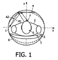
図1は、本発明による閉鎖型円筒状MR装置の空所1を示している。この図は、x軸及びy軸どちらにも直角な長手軸(z軸、回転軸)に沿ったものである。x軸、y軸及びz軸は、3次元座標系を表す。この空所は、60cmの内径を有し、xy平面に両方が存在する2つの開口部を有する。
FIG. 1 shows a
この空所の内側にいるのは、患者ベッド3に横たわる患者2である。患者ベッド3は部分的に湾曲した主面5を有するものの、その中央部分は、概ね平坦であり、zy平面内に存在する。患者は、患者ベッド3の主面5に垂直なx軸において目を向ける。患者の頭6の上方にあるのは、zy平面内に、したがって患者ベッド3の主面5に平行に配置される平坦な鏡4である。鏡から座標系の中心までの距離は27cmである。鏡4の中心は、上部カバー8に対して3cmの距離を有する。
Inside this void is the
この鏡は、当該カバーの中に一体化され、当該カバーがこの領域において平坦化されるようになっている。代替例においては、この鏡をQBC(quadrature body coil)の内側に置き、そのQBCカバー8が透明なものに選択されるようにすることができる。この場合、鏡4から患者ベッド3までの距離を長くすることができ、鏡4を大きくすることができる。その場合、知覚される空間はさらに大きくなる。
The mirror is integrated into the cover so that the cover is flattened in this area. In an alternative example, the mirror can be placed inside a QBC (quadrature body coil) so that the QBC cover 8 is selected to be transparent. In this case, the distance from the
代替例として、このMR装置のQBC(及びこれに伴う空所)は、xy平面内に円形を呈しないが、楕円形状を呈する。これは、点線によって示されている。 As an alternative, the QBC (and associated void) of this MR device does not exhibit a circle in the xy plane, but exhibits an elliptical shape. This is indicated by the dotted line.
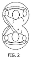
患者2が患者ベッド3に横たわるときに患者2が持つ知覚は、矢印A1,A2により示される。患者が上を見ると、患者は、自分自身を見ることができ、或いはその左右を見ることができる。経験的空間は、図2により示されるように窓を通じて見るようなものである。その印象は、患者の顔7が鏡から15cm離れていないものの自分の鏡像2´から30cm離れたものとなる。これにより、患者2は、自分自身と、自分の鏡像2´との間に鏡4のない場合よりも大きな空間を知覚する。
The perception that the
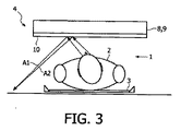
図3は、QBC(図示せず)の上部に平坦カバー8を備える開放型MRシステムを示している。カバー8は、厚さ2mmであり、ポリカーボネートにより作られる。カバー8は、金属のない非伝導性反射層10の基板9として振る舞う。カバー8及び層10は、1mの直径を有する円形鏡4の構成を視覚化するために正確な縮尺に従っていない。
FIG. 3 shows an open MR system with a flat cover 8 on top of a QBC (not shown). The cover 8 has a thickness of 2 mm and is made of polycarbonate. The cover 8 behaves as the substrate 9 of the non-conductive
図4は、図3のMR装置における患者ベッド3に患者が横たわるときの患者2の持つ知覚を示している。図2の状況と同様に、知覚される空間は、実際の空間よりも大きい。これは、患者2から自分の鏡像2´までの距離が鏡4までのものよりも大きいからである。
FIG. 4 shows the perception of the
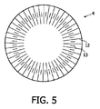
図5は、開放型MR装置において使用可能な鏡の実施例を示している。鏡4は、直径1mを有し、厚さ0.1 mのアルミニウムの層を含んでいる。鏡4は、交互に配された長いスリット12と短いスリット13とを有する。スリット12,13の全ては、半径方向に配され電気的経路長を長くする。小さめのスリット13は、RF場強度が特に高い領域に配される。
FIG. 5 shows an example of a mirror that can be used in an open MR apparatus. The
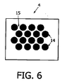
図6は、多数の金属領域14からなる層10を有する鏡4を示している。このガルヴァーニ電気の領域14は、小さな点状体であり、ここでは、領域15が金属を含まず、これにより金属領域14の間の電気的接続を回避している。当該点状体のサイズは、図示のために正確な縮尺ではない。
FIG. 6 shows a
Claims (11)
Applications Claiming Priority (2)
| Application Number | Priority Date | Filing Date | Title |
|---|---|---|---|
| EP04105728 | 2004-11-12 | ||
| PCT/IB2005/053698 WO2006051497A1 (en) | 2004-11-12 | 2005-11-10 | Medical examination apparatus |
Publications (1)
| Publication Number | Publication Date |
|---|---|
| JP2008519640A true JP2008519640A (en) | 2008-06-12 |
Family
ID=35822628
Family Applications (1)
| Application Number | Title | Priority Date | Filing Date |
|---|---|---|---|
| JP2007540804A Pending JP2008519640A (en) | 2004-11-12 | 2005-11-10 | Medical testing equipment |
Country Status (5)
| Country | Link |
|---|---|
| US (1) | US20090082659A1 (en) |
| EP (1) | EP1827225A1 (en) |
| JP (1) | JP2008519640A (en) |
| CN (1) | CN100525704C (en) |
| WO (1) | WO2006051497A1 (en) |
Cited By (2)
| Publication number | Priority date | Publication date | Assignee | Title |
|---|---|---|---|---|
| WO2013046906A1 (en) * | 2011-09-30 | 2013-04-04 | 株式会社日立メディコ | Inspection device |
| JP2015208427A (en) * | 2014-04-25 | 2015-11-24 | 株式会社日立メディコ | Magnetic resonance imaging system |
Families Citing this family (23)
| Publication number | Priority date | Publication date | Assignee | Title |
|---|---|---|---|---|
| GB2436290B (en) * | 2006-03-21 | 2008-04-23 | Siemens Magnet Technology Ltd | Patient calming arrangements |
| US8593728B2 (en) * | 2009-02-19 | 2013-11-26 | Toyota Motor Engineering & Manufacturing North America, Inc. | Multilayer photonic structures |
| US10788608B2 (en) | 2007-08-12 | 2020-09-29 | Toyota Jidosha Kabushiki Kaisha | Non-color shifting multilayer structures |
| US9612369B2 (en) | 2007-08-12 | 2017-04-04 | Toyota Motor Engineering & Manufacturing North America, Inc. | Red omnidirectional structural color made from metal and dielectric layers |
| US10870740B2 (en) | 2007-08-12 | 2020-12-22 | Toyota Jidosha Kabushiki Kaisha | Non-color shifting multilayer structures and protective coatings thereon |
| US8329247B2 (en) | 2009-02-19 | 2012-12-11 | Toyota Motor Engineering & Manufacturing North America, Inc. | Methods for producing omni-directional multi-layer photonic structures |
| US10048415B2 (en) | 2007-08-12 | 2018-08-14 | Toyota Motor Engineering & Manufacturing North America, Inc. | Non-dichroic omnidirectional structural color |
| US10690823B2 (en) | 2007-08-12 | 2020-06-23 | Toyota Motor Corporation | Omnidirectional structural color made from metal and dielectric layers |
| US8861087B2 (en) | 2007-08-12 | 2014-10-14 | Toyota Motor Corporation | Multi-layer photonic structures having omni-directional reflectivity and coatings incorporating the same |
| US9739917B2 (en) | 2007-08-12 | 2017-08-22 | Toyota Motor Engineering & Manufacturing North America, Inc. | Red omnidirectional structural color made from metal and dielectric layers |
| US8257784B2 (en) | 2010-08-10 | 2012-09-04 | Toyota Motor Engineering & Manufacturing North America, Inc. | Methods for identifying articles of manufacture |
| US8196823B2 (en) | 2010-08-10 | 2012-06-12 | Toyota Motor Engineering & Manufacturing North America, Inc. | Optical lock systems and methods |
| DE102010039469A1 (en) | 2010-08-18 | 2012-02-23 | Siemens Aktiengesellschaft | Medical imaging device |
| US10067265B2 (en) | 2010-10-12 | 2018-09-04 | Toyota Motor Engineering & Manufacturing North America, Inc. | Semi-transparent reflectors |
| US9658375B2 (en) | 2012-08-10 | 2017-05-23 | Toyota Motor Engineering & Manufacturing North America, Inc. | Omnidirectional high chroma red structural color with combination metal absorber and dielectric absorber layers |
| US9664832B2 (en) | 2012-08-10 | 2017-05-30 | Toyota Motor Engineering & Manufacturing North America, Inc. | Omnidirectional high chroma red structural color with combination semiconductor absorber and dielectric absorber layers |
| US9678260B2 (en) | 2012-08-10 | 2017-06-13 | Toyota Motor Engineering & Manufacturing North America, Inc. | Omnidirectional high chroma red structural color with semiconductor absorber layer |
| JP6324514B2 (en) * | 2013-09-30 | 2018-05-16 | コーニンクレッカ フィリップス エヌ ヴェKoninklijke Philips N.V. | A way to create an ambient experience |
| JP6741586B2 (en) | 2014-04-01 | 2020-08-19 | トヨタ モーター エンジニアリング アンド マニュファクチャリング ノース アメリカ,インコーポレイティド | Multi-layer structure without color shift |
| US9810824B2 (en) | 2015-01-28 | 2017-11-07 | Toyota Motor Engineering & Manufacturing North America, Inc. | Omnidirectional high chroma red structural colors |
| CN104840199A (en) * | 2015-06-02 | 2015-08-19 | 中国人民解放军南京军区南京总医院 | Nuclear magnetic resonance examination claustrophobic slow-release device |
| CN110025313A (en) * | 2019-04-01 | 2019-07-19 | 广东职业技术学院 | A kind of comprehensive physical examination instrument of nuclear magnetic resonance |
| EP3816646A1 (en) | 2019-10-28 | 2021-05-05 | Koninklijke Philips N.V. | Monitoring system with a camera and non-metallic mirror for magnetic resonance examination system |
Citations (9)
| Publication number | Priority date | Publication date | Assignee | Title |
|---|---|---|---|---|
| JPS6125105A (en) * | 1984-07-13 | 1986-02-04 | Nitto Electric Ind Co Ltd | Reflection type phase difference plate |
| JPH0219137A (en) * | 1988-07-06 | 1990-01-23 | Fujitsu Ltd | Nuclear magnetic resonance image pickup device |
| JPH04246328A (en) * | 1991-01-31 | 1992-09-02 | Shimadzu Corp | Magnetic resonance imaging device |
| JPH0524005U (en) * | 1991-09-17 | 1993-03-30 | 株式会社日立製作所 | MR imaging device |
| JPH05344964A (en) * | 1992-06-15 | 1993-12-27 | Toshiba Corp | CT device |
| JP2002336212A (en) * | 2001-04-27 | 2002-11-26 | Ge Medical Systems Global Technology Co Llc | Magnetic resonance imaging apparatus |
| JP2003052663A (en) * | 2001-08-08 | 2003-02-25 | Hitachi Medical Corp | Magnetic resonance imaging apparatus |
| WO2003032838A2 (en) * | 2001-10-19 | 2003-04-24 | Koninklijke Philips Electronics N.V. | Multimodality medical imaging system and method with patient handling assembly |
| JP2004174930A (en) * | 2002-11-27 | 2004-06-24 | Ricoh Co Ltd | Resin reflector and method of manufacturing the same |
Family Cites Families (8)
| Publication number | Priority date | Publication date | Assignee | Title |
|---|---|---|---|---|
| US4650299A (en) * | 1984-09-28 | 1987-03-17 | General Electric Company | Visual communication system |
| FR2623996A1 (en) | 1987-12-08 | 1989-06-09 | Thomson Csf | PATIENT MONITORING DEVICE IN MEDICAL EXAMINING APPARATUS |
| DE3935083A1 (en) * | 1989-10-20 | 1991-06-13 | Siemens Ag | MEASURING ARRANGEMENT FOR DETECTING A BREATHING MOTION |
| JP2774777B2 (en) * | 1994-11-25 | 1998-07-09 | 株式会社日立メディコ | Magnetic resonance imaging device |
| US5825563A (en) * | 1995-09-12 | 1998-10-20 | General Electric Company | Mirror and support for use in a magnetic resonance imaging device |
| US5794621A (en) * | 1995-11-03 | 1998-08-18 | Massachusetts Institute Of Technology | System and method for medical imaging utilizing a robotic device, and robotic device for use in medical imaging |
| DE10158313A1 (en) * | 2001-11-28 | 2003-06-26 | Siemens Ag | Medical investigation device with optically magnified inner chamber has stereoscopic image carrier, especially with no metal content, in patient's field of view to simulate larger volume |
| US20060074305A1 (en) * | 2004-09-30 | 2006-04-06 | Varian Medical Systems Technologies, Inc. | Patient multimedia display |
-
2005
- 2005-11-10 US US11/719,101 patent/US20090082659A1/en not_active Abandoned
- 2005-11-10 EP EP05807801A patent/EP1827225A1/en not_active Withdrawn
- 2005-11-10 WO PCT/IB2005/053698 patent/WO2006051497A1/en not_active Ceased
- 2005-11-10 CN CNB2005800387494A patent/CN100525704C/en not_active Expired - Fee Related
- 2005-11-10 JP JP2007540804A patent/JP2008519640A/en active Pending
Patent Citations (9)
| Publication number | Priority date | Publication date | Assignee | Title |
|---|---|---|---|---|
| JPS6125105A (en) * | 1984-07-13 | 1986-02-04 | Nitto Electric Ind Co Ltd | Reflection type phase difference plate |
| JPH0219137A (en) * | 1988-07-06 | 1990-01-23 | Fujitsu Ltd | Nuclear magnetic resonance image pickup device |
| JPH04246328A (en) * | 1991-01-31 | 1992-09-02 | Shimadzu Corp | Magnetic resonance imaging device |
| JPH0524005U (en) * | 1991-09-17 | 1993-03-30 | 株式会社日立製作所 | MR imaging device |
| JPH05344964A (en) * | 1992-06-15 | 1993-12-27 | Toshiba Corp | CT device |
| JP2002336212A (en) * | 2001-04-27 | 2002-11-26 | Ge Medical Systems Global Technology Co Llc | Magnetic resonance imaging apparatus |
| JP2003052663A (en) * | 2001-08-08 | 2003-02-25 | Hitachi Medical Corp | Magnetic resonance imaging apparatus |
| WO2003032838A2 (en) * | 2001-10-19 | 2003-04-24 | Koninklijke Philips Electronics N.V. | Multimodality medical imaging system and method with patient handling assembly |
| JP2004174930A (en) * | 2002-11-27 | 2004-06-24 | Ricoh Co Ltd | Resin reflector and method of manufacturing the same |
Cited By (3)
| Publication number | Priority date | Publication date | Assignee | Title |
|---|---|---|---|---|
| WO2013046906A1 (en) * | 2011-09-30 | 2013-04-04 | 株式会社日立メディコ | Inspection device |
| JP5663097B2 (en) * | 2011-09-30 | 2015-02-04 | 株式会社日立メディコ | Inspection device |
| JP2015208427A (en) * | 2014-04-25 | 2015-11-24 | 株式会社日立メディコ | Magnetic resonance imaging system |
Also Published As
| Publication number | Publication date |
|---|---|
| US20090082659A1 (en) | 2009-03-26 |
| CN101056577A (en) | 2007-10-17 |
| WO2006051497A1 (en) | 2006-05-18 |
| EP1827225A1 (en) | 2007-09-05 |
| CN100525704C (en) | 2009-08-12 |
Similar Documents
| Publication | Publication Date | Title |
|---|---|---|
| JP2008519640A (en) | Medical testing equipment | |
| Fagan et al. | 7T MR safety | |
| McElcheran et al. | Numerical simulations of realistic lead trajectories and an experimental verification support the efficacy of parallel radiofrequency transmission to reduce heating of deep brain stimulation implants during MRI | |
| Yang et al. | Reducing SAR and enhancing cerebral signal‐to‐noise ratio with high permittivity padding at 3 T | |
| Graedel et al. | An anatomically realistic temperature phantom for radiofrequency heating measurements | |
| Katscher et al. | Determination of electric conductivity and local SAR via B1 mapping | |
| Juchem et al. | Magnetic field modeling with a set of individual localized coils | |
| Liu et al. | Determining electrical properties based on B 1 fields measured in an MR scanner using a multi-channel transmit/receive coil: a general approach | |
| US9149205B2 (en) | Breast coil for use in magnetic resonance imaging | |
| Wintermark et al. | T1-weighted MRI as a substitute to CT for refocusing planning in MR-guided focused ultrasound | |
| Puchnin et al. | Metamaterial inspired wireless coil for clinical breast imaging | |
| US10908238B2 (en) | Magnetic resonance coil unit and method for its manufacture | |
| JP5666091B2 (en) | Magnetic tracking system for imaging system | |
| JPH069173B2 (en) | Cylindrical electromagnet | |
| Brown et al. | Design and application of combined 8-channel transmit and 10-channel receive arrays and radiofrequency shimming for 7-T shoulder magnetic resonance imaging | |
| JP4188384B2 (en) | Magnetic resonance imaging system | |
| Abel et al. | Flexible array coil for cervical and extraspinal (FACE) MRI at 3.0 Tesla | |
| WO2007108190A1 (en) | Magnetic resonance imager and rf coil for magnetic resonance imager | |
| Lechner-Greite et al. | Minimizing eddy currents induced in the ground plane of a large phased-array ultrasound applicator for echo-planar imaging-based MR thermometry | |
| US20190170838A1 (en) | Coil apparatus, magnetic resonance imaging apparatus, and method of controlling the coil apparatus | |
| Kim et al. | Development of double‐layer coupled coil for improving S/N in 7 T small‐animal MRI | |
| Kato et al. | < Editors’ Choice>: Evaluation of system-related magnetic resonance imaging geometric distortion in radiation therapy treatment planning: two approaches and effectiveness of three-dimensional distortion correction | |
| EP1733245B1 (en) | System for magnetic resonance imaging | |
| Tatebe et al. | Influence of geometric and material properties on artifacts generated by interventional MRI devices: Relevance to PRF‐shift thermometry | |
| Zanovello et al. | An ideal dielectric coat to avoid prosthesis RF-artefacts in magnetic resonance imaging |
Legal Events
| Date | Code | Title | Description |
|---|---|---|---|
| A621 | Written request for application examination |
Free format text: JAPANESE INTERMEDIATE CODE: A621 Effective date: 20081107 |
|
| A977 | Report on retrieval |
Free format text: JAPANESE INTERMEDIATE CODE: A971007 Effective date: 20110727 |
|
| A131 | Notification of reasons for refusal |
Free format text: JAPANESE INTERMEDIATE CODE: A131 Effective date: 20110728 |
|
| A02 | Decision of refusal |
Free format text: JAPANESE INTERMEDIATE CODE: A02 Effective date: 20120110 |