JP2008520902A - Variable capacity rotary compressor - Google Patents
Variable capacity rotary compressor Download PDFInfo
- Publication number
- JP2008520902A JP2008520902A JP2007542931A JP2007542931A JP2008520902A JP 2008520902 A JP2008520902 A JP 2008520902A JP 2007542931 A JP2007542931 A JP 2007542931A JP 2007542931 A JP2007542931 A JP 2007542931A JP 2008520902 A JP2008520902 A JP 2008520902A
- Authority
- JP
- Japan
- Prior art keywords
- vane
- rotary compressor
- pressure
- variable displacement
- casing
- Prior art date
- Legal status (The legal status is an assumption and is not a legal conclusion. Google has not performed a legal analysis and makes no representation as to the accuracy of the status listed.)
- Granted
Links
Images




Classifications
-
- F—MECHANICAL ENGINEERING; LIGHTING; HEATING; WEAPONS; BLASTING
- F04—POSITIVE - DISPLACEMENT MACHINES FOR LIQUIDS; PUMPS FOR LIQUIDS OR ELASTIC FLUIDS
- F04C—ROTARY-PISTON, OR OSCILLATING-PISTON, POSITIVE-DISPLACEMENT MACHINES FOR LIQUIDS; ROTARY-PISTON, OR OSCILLATING-PISTON, POSITIVE-DISPLACEMENT PUMPS
- F04C28/00—Control of, monitoring of, or safety arrangements for, pumps or pumping installations specially adapted for elastic fluids
- F04C28/06—Control of, monitoring of, or safety arrangements for, pumps or pumping installations specially adapted for elastic fluids specially adapted for stopping, starting, idling or no-load operation
- F04C28/065—Capacity control using a multiplicity of units or pumping capacities, e.g. multiple chambers, individually switchable or controllable
-
- F—MECHANICAL ENGINEERING; LIGHTING; HEATING; WEAPONS; BLASTING
- F04—POSITIVE - DISPLACEMENT MACHINES FOR LIQUIDS; PUMPS FOR LIQUIDS OR ELASTIC FLUIDS
- F04C—ROTARY-PISTON, OR OSCILLATING-PISTON, POSITIVE-DISPLACEMENT MACHINES FOR LIQUIDS; ROTARY-PISTON, OR OSCILLATING-PISTON, POSITIVE-DISPLACEMENT PUMPS
- F04C18/00—Rotary-piston pumps specially adapted for elastic fluids
- F04C18/30—Rotary-piston pumps specially adapted for elastic fluids having the characteristics covered by two or more of groups F04C18/02, F04C18/08, F04C18/22, F04C18/24, F04C18/48, or having the characteristics covered by one of these groups together with some other type of movement between co-operating members
- F04C18/34—Rotary-piston pumps specially adapted for elastic fluids having the characteristics covered by two or more of groups F04C18/02, F04C18/08, F04C18/22, F04C18/24, F04C18/48, or having the characteristics covered by one of these groups together with some other type of movement between co-operating members having the movement defined in group F04C18/08 or F04C18/22 and relative reciprocation between the co-operating members
- F04C18/356—Rotary-piston pumps specially adapted for elastic fluids having the characteristics covered by two or more of groups F04C18/02, F04C18/08, F04C18/22, F04C18/24, F04C18/48, or having the characteristics covered by one of these groups together with some other type of movement between co-operating members having the movement defined in group F04C18/08 or F04C18/22 and relative reciprocation between the co-operating members with vanes reciprocating with respect to the outer member
- F04C18/3562—Rotary-piston pumps specially adapted for elastic fluids having the characteristics covered by two or more of groups F04C18/02, F04C18/08, F04C18/22, F04C18/24, F04C18/48, or having the characteristics covered by one of these groups together with some other type of movement between co-operating members having the movement defined in group F04C18/08 or F04C18/22 and relative reciprocation between the co-operating members with vanes reciprocating with respect to the outer member the inner and outer member being in contact along one line or continuous surfaces substantially parallel to the axis of rotation
- F04C18/3564—Rotary-piston pumps specially adapted for elastic fluids having the characteristics covered by two or more of groups F04C18/02, F04C18/08, F04C18/22, F04C18/24, F04C18/48, or having the characteristics covered by one of these groups together with some other type of movement between co-operating members having the movement defined in group F04C18/08 or F04C18/22 and relative reciprocation between the co-operating members with vanes reciprocating with respect to the outer member the inner and outer member being in contact along one line or continuous surfaces substantially parallel to the axis of rotation the surfaces of the inner and outer member, forming the working space, being surfaces of revolution
-
- F—MECHANICAL ENGINEERING; LIGHTING; HEATING; WEAPONS; BLASTING
- F04—POSITIVE - DISPLACEMENT MACHINES FOR LIQUIDS; PUMPS FOR LIQUIDS OR ELASTIC FLUIDS
- F04C—ROTARY-PISTON, OR OSCILLATING-PISTON, POSITIVE-DISPLACEMENT MACHINES FOR LIQUIDS; ROTARY-PISTON, OR OSCILLATING-PISTON, POSITIVE-DISPLACEMENT PUMPS
- F04C23/00—Combinations of two or more pumps, each being of rotary-piston or oscillating-piston type, specially adapted for elastic fluids; Pumping installations specially adapted for elastic fluids; Multi-stage pumps specially adapted for elastic fluids
- F04C23/008—Hermetic pumps
Landscapes
- Engineering & Computer Science (AREA)
- Mechanical Engineering (AREA)
- General Engineering & Computer Science (AREA)
- Applications Or Details Of Rotary Compressors (AREA)
Abstract
本発明による容量可変型ロータリ圧縮機は、吐出圧状態を維持するケーシング100と、ケーシング100の内部に固定設置されて駆動力を発生するモータ200と、ケーシング100の内部に固定設置され、モータ200の回転軸230に偏心結合されて旋回運動するローリングピストン340、430及びローリングピストン340、430に接して直線運動するベーン350、440により冷媒を圧縮する少なくとも1つのシリンダ組立体300、400と、ベーン440に加えられる圧力差に応じて、ベーン440をローリングピストン430から離隔させて拘束するか、又はベーン440を解除してローリングピストン430に接するようにするベーン拘束ユニット500とを含む。前記ロータリ圧縮機は、全体構造を簡単にし、組立工程を簡素化し、これにより生産コストを低減して生産性を向上させる。また、ベーン440をシステムの圧力差を利用して拘束することにより信頼性を高める。特に、ストッパ550を利用した場合は、その信頼性をさらに高める。 The variable displacement rotary compressor according to the present invention includes a casing 100 that maintains a discharge pressure state, a motor 200 that is fixedly installed inside the casing 100 and generates a driving force, and a motor 200 that is fixedly installed inside the casing 100. Rolling pistons 340 and 430 that are eccentrically coupled to the rotating shaft 230 of the rotating shaft 230 and at least one cylinder assembly 300 and 400 that compresses the refrigerant by the vanes 350 and 440 that linearly move in contact with the rolling pistons 340 and 430, and the vanes A vane restraining unit 500 that restrains the vane 440 from being separated from the rolling piston 430 or releases the vane 440 to contact the rolling piston 430 according to a pressure difference applied to the 440. The rotary compressor simplifies the overall structure and simplifies the assembly process, thereby reducing production costs and improving productivity. In addition, the reliability is improved by restraining the vane 440 by utilizing the pressure difference of the system. In particular, when the stopper 550 is used, the reliability is further improved.
Description
本発明はロータリ圧縮機に関し、特に、ベーンスロットの側面に吸入圧又は吐出圧を供給することによりベーンを拘束又は解除する容量可変型ロータリ圧縮機に関する。 The present invention relates to a rotary compressor, and more particularly to a variable displacement rotary compressor that restrains or releases a vane by supplying suction pressure or discharge pressure to a side surface of the vane slot.
一般に、空気調和機は、室内温度を設定温度に維持して室内を快適な状態に維持する。このような空気調和機は冷却システムを含み、冷却システムは、冷媒を圧縮する圧縮機と、圧縮機で圧縮された冷媒を凝縮することにより外部に熱を放出する凝縮器と、凝縮器で凝縮された冷媒の圧力を低下させる膨張バルブと、膨張バルブを経た冷媒を蒸発させることにより外部の熱を吸収する蒸発器とから構成される。 Generally, an air conditioner maintains a room in a comfortable state by maintaining the room temperature at a set temperature. Such an air conditioner includes a cooling system, which includes a compressor that compresses the refrigerant, a condenser that releases heat by condensing the refrigerant compressed by the compressor, and a condenser that condenses the refrigerant. The expansion valve is configured to reduce the pressure of the refrigerant, and an evaporator that absorbs external heat by evaporating the refrigerant that has passed through the expansion valve.
冷却システムにおいては、電力が供給されて圧縮機が動作することによってその圧縮機から吐出された高温高圧の冷媒が、凝縮器、膨張バルブ、蒸発器を順次経た後に圧縮機に吸入され、このような過程が繰り返される。上記過程において、凝縮器が熱を発生し、蒸発器が外部の熱を吸収して冷気を形成するが、凝縮器から発生する熱と蒸発器で形成される冷気を選択的に室内に循環させることにより、室内を快適な状態に維持する。 In the cooling system, the high-temperature and high-pressure refrigerant discharged from the compressor when electric power is supplied and the compressor is operated sequentially passes through the condenser, the expansion valve, and the evaporator, and then is sucked into the compressor. The process is repeated. In the above process, the condenser generates heat, and the evaporator absorbs external heat to form cold air. The heat generated from the condenser and the cold air formed by the evaporator are selectively circulated in the room. This keeps the room comfortable.
一方、冷却システムを構成する圧縮機の種類は多様であるが、特に、空気調和機に適用される圧縮機としては、ロータリ圧縮機、スクロール圧縮機などがある。 On the other hand, there are various types of compressors constituting the cooling system. In particular, compressors applied to the air conditioner include a rotary compressor and a scroll compressor.
このような空気調和機の製造において最も重要な要素は、製品の競争力を高めるために製造コストを最小化することと、空気調和機の消費電力を最小化することである。 The most important factors in the manufacture of such an air conditioner are minimizing the manufacturing cost in order to increase the competitiveness of the product and minimizing the power consumption of the air conditioner.
消費電力を最小化するために、空気調和機は、その空気調和機が設置された室内空間の負荷、すなわち、温度条件に応じて運転を行わなければならない。すなわち、空気調和機は、室内温度が急激に上昇した場合、設定温度を維持するために、その急激な温度変化(過度な負荷)に応じて冷気の発生が多くなるようにパワーモードに切り替え、室内温度の設定温度からの変化幅が小さい場合、設定温度を維持するために、冷気の発生が少なくなるようにセーブモードに切り替える。 In order to minimize the power consumption, the air conditioner must be operated according to the load of the indoor space in which the air conditioner is installed, that is, the temperature condition. That is, the air conditioner switches to the power mode so that the generation of cool air increases in accordance with the rapid temperature change (excessive load) in order to maintain the set temperature when the room temperature rises rapidly, When the change width of the room temperature from the set temperature is small, the mode is switched to the save mode so as to reduce the generation of cool air in order to maintain the set temperature.
このようなモード切替を実現するために、圧縮機で圧縮されて吐出される冷媒の量を調節することにより、冷却システムの冷却能力を変化させる。 In order to realize such mode switching, the cooling capacity of the cooling system is changed by adjusting the amount of refrigerant compressed and discharged by the compressor.
圧縮機から吐出される冷媒の量を調節する方法の1つとして、圧縮機を構成する駆動モータの回転数を変化させることのできるインバータモータを適用する方法がある。空気調和機が設置された室内空間の負荷に応じて圧縮機の駆動モータの回転数を調節することにより、圧縮機から吐出される冷媒の量を調節する。圧縮機から吐出される冷媒の量が変化することによって、凝縮器から発生する熱と蒸発器で形成される冷気の量が調節される。 One method of adjusting the amount of refrigerant discharged from the compressor is to apply an inverter motor that can change the rotational speed of a drive motor that constitutes the compressor. The amount of refrigerant discharged from the compressor is adjusted by adjusting the number of revolutions of the drive motor of the compressor according to the load in the indoor space where the air conditioner is installed. By changing the amount of refrigerant discharged from the compressor, the heat generated from the condenser and the amount of cold air formed by the evaporator are adjusted.
しかし、圧縮機の駆動モータとしてインバータモータを適用した場合、インバータモータが非常に高価であるため製造コストが上昇し、価格競争力が低下するという欠点があった。 However, when an inverter motor is applied as a drive motor for a compressor, the inverter motor is very expensive, so that there is a disadvantage that the manufacturing cost increases and the price competitiveness decreases.
これにより、近年、インバータ方式に代えて、圧縮機のシリンダで圧縮される冷媒の一部をシリンダの外部にバイパスして圧縮室の容量を変化させる技術、又はベーンをローリングピストンから離隔させて圧縮室と吸入室を連通することにより空転させる技術が広く開発されている。しかし、前者は、冷媒をシリンダの外部にバイパスするパイプシステムが複雑であるため、冷媒の流動抵抗を増加させて効率を低下させるという問題があった。また、後者は、ベーンをベーンスロットに拘束するために磁石又は引張スプリングを利用するが、このためには複雑な設置工程が要求される。特に、磁石を利用する場合は、圧縮機又は冷却システムの金属粉がベーンに付着してベアリング面を損傷させるという問題があった。 As a result, in recent years, instead of the inverter system, a part of the refrigerant compressed in the compressor cylinder is bypassed outside the cylinder to change the capacity of the compression chamber, or the vane is separated from the rolling piston for compression. The technology of idling by communicating the chamber and the suction chamber has been widely developed. However, since the pipe system for bypassing the refrigerant to the outside of the cylinder is complicated, the former has a problem that the flow resistance of the refrigerant is increased to lower the efficiency. The latter uses magnets or tension springs to constrain the vanes to the vane slots, but this requires a complicated installation process. In particular, when a magnet is used, there is a problem that metal powder of the compressor or the cooling system adheres to the vane and damages the bearing surface.
そこで、本発明は、空転時にローリングピストンから離れたベーンを容易に拘束することができ、信頼性を高めることができる容量可変型ロータリ圧縮機を提供することを目的とする。 Accordingly, an object of the present invention is to provide a variable displacement rotary compressor that can easily restrain a vane that is separated from a rolling piston during idling and can improve reliability.
上記の目的を達成するために、本発明は、吐出圧状態を維持するケーシングと、ケーシングの内部に固定設置されて駆動力を発生するモータと、ケーシングの内部に固定設置され、モータの回転軸に偏心結合されて旋回運動するローリングピストン及びローリングピストンに接して直線運動するベーンにより冷媒を圧縮する少なくとも1つのシリンダ組立体と、ベーンに加えられる圧力差に応じて、ベーンをローリングピストンから離隔させて拘束するか、又はベーンを解除してローリングピストンに接するようにするベーン拘束ユニットとを含む容量可変型ロータリ圧縮機を提供する。 In order to achieve the above object, the present invention provides a casing that maintains a discharge pressure state, a motor that is fixedly installed inside the casing and generates a driving force, a fixed installation inside the casing, and a rotating shaft of the motor. A rolling piston that is eccentrically coupled to the rolling piston, at least one cylinder assembly that compresses the refrigerant by a vane that moves linearly in contact with the rolling piston, and the vane is separated from the rolling piston in accordance with a pressure difference applied to the vane. Or a vane restraining unit that releases a vane and comes into contact with a rolling piston.
本発明による容量可変型ロータリ圧縮機は、ベーンをその前方側と後方側の圧力差及び側面に加えられる圧力差を利用して拘束することにより、全体構造を簡単にし、組立工程を簡素化し、これにより生産コストを低減して生産性を向上させる。また、ベーンをシステムの圧力差を利用して拘束することにより信頼性を高める。特に、ストッパを利用した場合は、その信頼性をさらに高める。 The variable displacement rotary compressor according to the present invention restrains the vane by utilizing the pressure difference between the front side and the rear side and the pressure difference applied to the side surface, thereby simplifying the overall structure and simplifying the assembly process, This reduces production costs and improves productivity. In addition, the reliability is improved by restraining the vane by utilizing the pressure difference of the system. In particular, when a stopper is used, the reliability is further increased.
以下、本発明による容量可変型ロータリ圧縮機の好ましい実施形態について、添付図面を参照して詳細に説明する。 Hereinafter, preferred embodiments of a variable displacement rotary compressor according to the present invention will be described in detail with reference to the accompanying drawings.
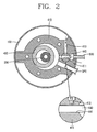
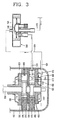
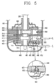
図1は本発明による容量可変型ロータリ圧縮機を示す縦断面図であり、図2は図1のI−I線断面図であり、図3及び図4は本発明による容量可変型ロータリ圧縮機においてベーンを拘束する一実施形態における正常運転時及びセーブ運転時を示す縦断面図であり、図5は本発明による容量可変型ロータリ圧縮機においてベーンを拘束する他の実施形態を示す縦断面図である。 FIG. 1 is a longitudinal sectional view showing a variable displacement rotary compressor according to the present invention, FIG. 2 is a sectional view taken along the line II of FIG. 1, and FIGS. 3 and 4 are variable displacement rotary compressors according to the present invention. FIG. 5 is a longitudinal sectional view showing a normal operation and a save operation in one embodiment of restraining the vane in FIG. 5, and FIG. 5 is a longitudinal sectional view showing another embodiment of restraining the vane in the variable displacement rotary compressor according to the present invention. It is.
図1に示すように、本発明によるツインロータリ圧縮機は、複数のガス吸入管SP1、SP2及び1つのガス吐出管DPが連通するケーシング100と、ケーシング100の上側に設置されて回転力を発生する電動機構部200と、ケーシング100の下側に設置されて電動機構部200から発生した回転力により冷媒を圧縮する第1圧縮機構部300及び第2圧縮機構部400と、第2圧縮機構部400が正常運転又はセーブ運転を行うようにし、第2圧縮機構部400のセーブ運転時に第2ベーン440が第2ベーンスロット411に収納された状態を維持するようにするベーン拘束ユニット500とから構成される。
As shown in FIG. 1, the twin rotary compressor according to the present invention has a
電動機構部200は、定速駆動又は可変速(インバータ)駆動を行うもので、ケーシング100の内部に設置されて外部から電力を供給する固定子210と、固定子210の内部に所定の空隙を介して配置されて固定子210との相互作用により回転する回転子220と、回転子220に結合されて回転力を第1圧縮機構部300及び第2圧縮機構部400に伝達する回転軸230とから構成される。
The
第1圧縮機構部300は、環状に形成されてケーシング100の内部に設置される第1シリンダ310と、第1シリンダ310の上下両側を覆蓋して共に第1圧縮空間V1を形成し、回転軸230を半径方向に支持する上部ベアリングプレート(以下、上部ベアリングという)320及び中間ベアリングプレート(以下、中間ベアリングという)330と、回転軸230の上側偏心部に回転可能に結合され、第1シリンダ310の第1圧縮空間V1で旋回して冷媒を圧縮する第1ローリングピストン340と、第1ローリングピストン340の外周面に圧接するように第1シリンダ310に半径方向に移動可能に結合されて、第1シリンダ310の第1内部空間V1を第1吸入室と第1圧縮室に区画する第1ベーン350と、第1ベーン350の後方側を弾性支持するように圧縮スプリングからなるベーン支持スプリング360と、上部ベアリング320の中央付近に備えられた第1吐出口321の先端に開閉可能に結合され、第1内部空間V1の第1圧縮室から吐出される冷媒ガスの吐出を制御する第1吐出バルブ370と、第1吐出バルブ370を収納するように内部体積を有して上部ベアリング320に結合される第1マフラ380とから構成される。
The first
第2圧縮機構部400は、環状に形成されてケーシング100内部の第1シリンダ310の下側に設置される第2シリンダ410と、第2シリンダ410の上下両側を覆蓋して共に第2圧縮空間V2を形成し、回転軸230を半径方向及び軸方向に支持する中間ベアリング330及び下部ベアリング420と、回転軸230の下側偏心部に回転可能に結合され、第2シリンダ410の第2圧縮空間V2で旋回して冷媒を圧縮する第2ローリングピストン430と、第2ローリングピストン430の外周面に圧接するか、又は第2ローリングピストン430の外周面から離れるように、第2シリンダ410に半径方向に移動可能に結合されて、第2シリンダ410の第2圧縮空間V2を第2吸入室と第2圧縮室に区画又は連通する第2ベーン440と、下部ベアリング420の中央付近に備えられた第2吐出口421の先端に開閉可能に結合され、第2圧縮室から吐出される冷媒ガスの吐出を制御する第2吐出バルブ450と、第2吐出バルブ450を収納するように内部体積を有して下部ベアリング420に結合される第2マフラ460とから構成される。
The second
第2シリンダ410は、図2に示すように、第2圧縮空間V2を形成する内周面の一側に、第2ベーン440が半径方向に往復運動を行えるように第2ベーンスロット411が形成され、第2ベーンスロット411の一側には、冷媒を第2圧縮空間V2に案内する第2吸入口(図示せず)が半径方向に形成され、第2ベーンスロット411の他側には、冷媒をケーシング100の内部に吐出する第2吐出案内溝(図示せず)が軸方向に傾斜して形成される。また、第2ベーンスロット411の半径方向の後方側には、後述する共用側連結管530に連結されて第2ベーン440の後方側が吸入圧雰囲気又は吐出圧雰囲気となるように、密閉空間からなるベーンチャンバ412が形成される。さらに、第2シリンダ410には、第2ベーン440の運動方向に対して直交する方向又は傾斜方向にケーシング100の内部と第2ベーンスロット411を連通して、ケーシング100内部の吐出圧により第2ベーン440を拘束するベーン拘束流路413が形成される。
As shown in FIG. 2, the
ベーン拘束流路413は、図2に示すように、第2ベーン440を中心に第2シリンダ410の吐出案内溝(図示せず)側に位置し、第2シリンダ410の外周面から第2ベーンスロット411の中心に貫通して形成される。また、ベーン拘束流路413は、2段ドリルを利用して、第2ベーンスロット411側が狭く2段の段差を有するように形成される。さらに、ベーン拘束流路413は、第2ベーン440が直線運動を安定して行えるように、その出口端が第2ベーンスロット411の長手方向のほぼ中間に形成される。さらに、ベーン拘束流路413の断面積は、第2ベーンスロット411の縦断面積、すなわち、第2ベーン440の背面の断面積と等しいかそれより小さいことが、第2ベーン440が過度に拘束されることを防止できて好ましい。また、ベーン拘束流路413は、第2ベーン440の高さ方向に沿って複数(図においては、上下2段の場合を図示する)形成することができる。
As shown in FIG. 2, the vane restricting
ベーン拘束流路413は、図2に示すように、第2ベーン440の左右側面に対応するように、第2シリンダ410に横方向に形成することもでき、第2ベーン440の左右側面又は上下面に対応するように、中間ベアリング330又は下部ベアリング420に横方向又は縦方向に形成することもできる。
As shown in FIG. 2, the vane restricting
ベーン拘束ユニット500は、第2ガス吸入管SP2から分岐する吸入圧側連結管510と、ケーシング100の内部空間に連結される吐出圧側連結管520と、第2シリンダ410のベーンチャンバ412に連結され、吸入圧側連結管510及び吐出圧側連結管520に連通する共用側連結管530と、共用側連結管530を介して第2シリンダ410のベーンチャンバ412に連結される圧力切替バルブ540とから構成される。
The
吸入圧側連結管510は、第2シリンダ410の吸入側と、アキュムレータ110の入口側第2ガス吸入管SP2との間に連結される。
The suction pressure
吐出圧側連結管520は、ケーシング100の下半部に連通して、ケーシング100内部のオイルをベーンチャンバ412に直接流入させることもできるが、場合によっては、ガス吐出管DPの中間から分岐して連結することもできる。この場合、ベーンチャンバ412が密封されており、オイルが第2ベーン440と第2ベーンスロット411との間に供給されないことによって摩擦損失が発生する恐れがあるので、下部ベアリング420にオイル供給孔(図示せず)を形成して、第2ベーン440の往復運動時にオイルを供給する。
The discharge pressure
また、ベーン拘束ユニット500は、第2シリンダ410、中間ベアリング330、又は下部ベアリング420にベーン拘束流路413が形成されており、ベーンチャンバ412に吸入圧が供給されるとき、第2ベーンスロット411に収納される第2ベーン440を押して拘束するように構成されるか、又は図5に示すように、第2シリンダ410、中間ベアリング330、又は下部ベアリング420にストッパピン551及びピンスプリング552からなるストッパ550が設置されており、ベーンチャンバ412に吸入圧が供給されるとき、ストッパピン551がピンスプリング552に打ち勝って第2ベーン440をストッパピン551の反対側に密着させて拘束するか、又は第2ベーン440を直接係止して拘束するように構成される。
In the
図中の符号1は凝縮器、2は膨張機構、3は蒸発器、541はバルブハウジング、542はスライドバルブである。
In the figure,
以下、このような本発明による容量可変型ツインロータリ圧縮機の動作について説明する。 The operation of the variable capacity twin rotary compressor according to the present invention will be described below.
電動機構部200の固定子210に電力が供給されて回転子220が回転すると、回転子220と共に回転軸230が回転して電動機構部200の回転力を第1圧縮機構部300と第2圧縮機構部400に伝達する。第1圧縮機構部300と第2圧縮機構部400の両方を正常運転する場合は大容量の冷却能力が発生し、第1圧縮機構部300は正常運転して第2圧縮機構部400はセーブ運転する場合は小容量の冷却能力を発生する。
When electric power is supplied to the
ここで、圧縮機又はこれを備える冷却システムが正常運転を行う場合は、図3に示すように、スライドバルブ542が動作することによって、吸入圧側連結管510は遮断される反面、吐出圧側連結管520が共用側連結管530に連通して、第2シリンダ410のベーンチャンバ412には高圧である吐出圧のオイル又は冷媒が供給される。従って、ベーンチャンバ412の圧力により第2ベーン440が第2ローリングピストン430側に押されて、第2ローリングピストン430に圧接した状態を維持し、第2圧縮空間V2に流入した冷媒ガスを正常に圧縮して吐出する。ここで、第2シリンダ410に備えられたベーン拘束流路413を介して高圧の冷媒ガス又はオイルが供給されるが、ベーン拘束流路413の断面積が第2ベーンスロット411の半径方向の断面積よりも小さくて、第2ベーン440の側面への加圧力がベーンチャンバ412における前後方向の加圧力よりも低いため、第2ベーン440を拘束できなくなることによって、第2ベーン440は、第2ローリングピストン430の旋回運動によって持続的に前後方向に往復運動を行う。また、図5に示すように、ストッパ550が設置された場合も、ベーンチャンバ412が高圧の吐出圧を維持することによってストッパピン551両端の圧力が同一であるため、結局、ピンスプリング552によりストッパピン551が第2ベーン440を拘束できなくなる。
Here, when the compressor or the cooling system including the compressor operates normally, as shown in FIG. 3, the suction pressure
このようにして、第1ベーン350と第2ベーン440がそれぞれ、第1ローリングピストン340と第2ローリングピストン430に圧接して、第1圧縮空間V1と第2圧縮空間V2を吸入室と圧縮室に区画し、それぞれの吸入室に吸入される冷媒全体を圧縮して吐出することにより、圧縮機又はこれを備える冷却システムは100%運転を行う。
In this way, the
それに対し、圧縮機又はこれを備える冷却システムが起動時のようにセーブ運転を行う場合は、図4に示すように、圧力切替バルブ540のスライドバルブ542が正常運転とは反対に動作して、吸入圧側連結管510と共用側連結管530を連通し、これにより、ベーンチャンバ412には低圧の冷媒が流入し、相対的に高圧の第2圧縮空間V2の圧力により第2ベーン440がベーンチャンバ412側に押されて、第2ローリングピストン430から離れ、第2圧縮空間V2の吸入室と圧縮室が連通する。これにより、第2圧縮空間V2に吸入される冷媒が吸入室に漏洩して圧縮されず、結局、第2圧縮機構部400は圧縮を行えなくなる。ここで、第2シリンダ410に備えられたベーン拘束流路413を介して高圧のオイル又は冷媒ガスが流入して、第2ベーン440を第2ベーンスロット411の内部で拘束することにより、第2ベーン440が第2ローリングピストン430から離れた状態で動けなくなる。また、図5に示すように、ストッパ550が設置された場合も、ベーンチャンバ412が吸入圧を維持することによって、ストッパピン551両端の圧力差によりストッパピン551がピンスプリング552の弾性力に打ち勝って第2ベーン440側に移動して、第2ベーン440が中間ベアリング330に密着して拘束される。
On the other hand, when the compressor or the cooling system including the same performs the save operation as at the time of starting, as shown in FIG. 4, the
このようにして、第2シリンダ410の圧縮室と吸入室が連通することによって、第2シリンダ410の吸入室に吸入される冷媒全体が圧縮されず、第2ローリングピストン430の軌跡に沿って再び吸入室に移動して、第2圧縮機構部400が圧縮を行えなくなることによって、圧縮機又はこれを備える冷却システムは第1圧縮機構部300の容量だけ運転を行う。
In this way, the compression chamber and the suction chamber of the
以下、本発明による容量可変型ロータリ圧縮機のベーン拘束ユニットの他の実施形態について説明する。 Hereinafter, other embodiments of the vane restraining unit of the variable displacement rotary compressor according to the present invention will be described.
前述した実施形態は、ベーンチャンバ412に吸入圧が供給されて第2ベーン440がベーンスロット411に収納された状態で、吐出圧又はストッパを利用して第2ベーン440を拘束するものであるが、本実施形態は、第2シリンダ410の圧縮空間V2とベーンチャンバ412との圧力差を利用して第2ベーン440を拘束するものである。
In the above-described embodiment, the suction pressure is supplied to the
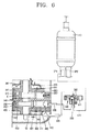
例えば、ベーン拘束ユニット500は、図6に示すように、第1ガス吸入管SP1から分岐する吸入圧側連結管510をベーンチャンバ412に連結される共用側連結管530に連通することによって第2圧縮機構部400がセーブ運転を行う場合は、正常運転を行う第1圧縮機構部300の吸入圧がセーブ運転を行う第2圧縮機構部400のベーンチャンバ412の圧力と同一に維持されるように構成される。
For example, as shown in FIG. 6, the
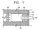
この場合、第1圧縮機構部300の第1圧縮空間V1と第2圧縮機構部400の第2圧縮空間V2には吸入圧の冷媒が供給されるが、第2圧縮機構部400に備えられたベーンチャンバ412が吸入圧を維持することによって、第2ベーン440がベーンチャンバ412の内側に移動し、これにより、第2圧縮機構部400の第2圧縮空間V2では圧縮室から吸入室への冷媒漏洩が発生して空転する。また、図7に示すように、第2シリンダ410の第2圧縮空間V2から発生した冷媒漏洩により、第2ガス案内管SP2では冷媒が停滞する現象が発生して、第2シリンダ410の第2圧縮空間V2の内部圧力(ほぼ中間圧力Pb)が、第1圧縮機構部300の吸入圧力Ps、すなわち、ベーンチャンバ412の内部圧力より高くなり、結局、第2ベーン440は第2ベーンスロット412に収納された状態を維持する。
In this case, the suction pressure refrigerant is supplied to the first compression space V1 of the first
その後、圧力切替バルブ540内のスライドバルブ542が移動して、吐出圧側連結管520と共用側連結管530が連通すると、第2圧縮機構部400のベーンチャンバ412が高圧となって第2シリンダ410の第2圧縮空間V2内の圧力より高くなり、これにより、第2ベーン440が第2ローリングピストン430に圧接した状態で第2圧縮機構部400が正常運転を行う。
Thereafter, when the
以下、本発明による容量可変型ロータリ圧縮機のベーン拘束ユニットのさらに他の実施形態について説明する。 Hereinafter, still another embodiment of the vane restraining unit of the variable displacement rotary compressor according to the present invention will be described.
前述した実施形態は、第2圧縮機構部400のベーンチャンバ412がケーシング100の内部空間と分離された密閉空間から構成されるものであるが、第2ベーン440の後方側がケーシング100の内部空間に連通するように開放空間から構成される場合も、圧力差を利用して第2ベーン440を拘束することができる。
In the above-described embodiment, the
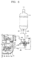
このために、図8に示すように、第2圧縮機構部400の第2ベーン440がケーシング100の内部空間の吐出圧により支持されるように、第2ベーン440の後方側がケーシング100の内部空間に連通し、下部ベアリング420、中間ベアリング330、又は第2シリンダ410には、第2ベーン440の前方側と後方側との圧力差により第2ベーン440を拘束又は解除するためのベーン拘束流路422が形成され、ベーン拘束流路422と第2シリンダ410の圧縮空間V2に吸入圧又は吐出圧の冷媒を選択的に供給できるように、吸入圧側連結管610、吐出圧側連結管620、共用側連結管630、及びシリンダ側連結管640が圧力切替バルブ650に連結される。
Therefore, as shown in FIG. 8, the rear side of the
例えば、圧力切替バルブ650は、4つの管路を有するバルブハウジング651の内部にスライドバルブ652がスライド可能に備えられて、スライドバルブ652が電磁石(図示せず)により動作して4つの管路を選択的に連通するもので、バルブハウジング651の第1管路は第2ガス吸入管SP2から延びる吸入圧側連結管610に連通し、第2管路はケーシング100の内部空間に連通する吐出圧側連結管620に連通し、第3管路はベーン拘束流路422に連通する共用側連結管630に連通し、第4管路は第2シリンダ410の吸入口に連通するシリンダ側連結管640に連通する。
For example, in the
第2ベーン440の後方側がケーシング100の内部空間に連通してオイルが持続的にケーシング100内に供給されるため、吐出圧側連結管640は、オイルの油面より高く設置してベーン拘束流路422に冷媒が供給されるようにしてもよい。
Since the rear side of the
以下、このような本発明による容量可変型ロータリ圧縮機において第2ベーンが拘束される過程を説明する。 Hereinafter, a process in which the second vane is restrained in the variable displacement rotary compressor according to the present invention will be described.
圧力切替バルブ650のスライドバルブ652が第1管路と第3管路を連通するように移動すると、残りの第2管路と第4管路が自動的に連通する。これにより、吐出圧側連結管620とシリンダ側連結管640が連通して高圧の吐出圧が第2シリンダ410の圧縮空間V2に供給されると共に、吸入圧側連結管610と共用側連結管630が連通して低圧の吸入圧がベーン拘束流路422に供給される。従って、第2ベーン440の後方側はケーシング100の内部空間の圧力と同一の高圧を維持する一方、第2ベーン440の前方側、すなわち、第2シリンダ410の圧縮空間V2の圧力は高圧を維持して圧力平衡状態となり、この状態で第2ベーン440の側面に低圧が供給されることによって、図9に示すように、第2ベーン440の前後両側に形成される高圧の吐出圧Pdがベーン拘束流路422に形成される低圧の吸入圧Ps側に漏洩することによって、第2ベーン440を強く拘束する。
When the
それに対し、圧力切替バルブ650のスライドバルブ652が第1管路と第4管路を連通し、残りの第2管路と第3管路を連通するように移動すると、第2シリンダ410の圧縮空間V2には吸入圧の冷媒が流入すると共に、ベーン拘束流路422には高圧の吐出圧が供給されて、第2ベーン440がその前方側と後方側との圧力差により、第2ローリングピストン430に向かって移動し、第2ローリングピストン430に圧接して正常運転する。
On the other hand, when the
図10に示すように、ベーン拘束流路422にストッパピン661とピンスプリング662とからなるストッパ660を設置した場合は、第2ベーン440をより堅固に拘束することができる。すなわち、圧力切替バルブ650を利用してベーン拘束流路422に吸入圧を供給した場合は、ベーン拘束流路422の圧力とピンスプリング661の弾性力とを合わせた力が、ケーシング100の内部空間の圧力より小さいため、ストッパピン661が第2ベーン440側に押されて第2ベーン440を拘束する反面、ベーン拘束流路422に吐出圧を供給した場合は、ストッパピン661がピンスプリング662の弾性力により移動して第2ベーン440の拘束を解除する。
As shown in FIG. 10, when the
以上の実施形態では、複数のシリンダ組立体を有するロータリ圧縮機でいずれか1つのシリンダ組立体にベーン拘束ユニットを設置した場合を例に説明したが、ベーン拘束ユニットは、それぞれのシリンダ組立体に設置することもでき、1つのシリンダ組立体を有するシングルロータリ圧縮機にも同様に適用することができる。 In the above embodiment, the case where the vane restraining unit is installed in any one cylinder assembly in the rotary compressor having a plurality of cylinder assemblies has been described as an example. However, the vane restraining unit is provided in each cylinder assembly. It can also be installed and can be similarly applied to a single rotary compressor having one cylinder assembly.
Claims (15)
前記ケーシングの内部に固定設置されて駆動力を発生するモータと、
前記ケーシングの内部に固定設置され、前記モータの回転軸に偏心結合されて旋回運動するローリングピストン及び前記ローリングピストンに接して直線運動するベーンにより冷媒を圧縮する少なくとも1つのシリンダ組立体と、
前記ベーンに加えられる圧力差に応じて、前記ベーンを前記ローリングピストンから離隔させて拘束するか、又は前記ベーンを解除して前記ローリングピストンに接するようにするベーン拘束ユニットと、
を含むことを特徴とする、容量可変型ロータリ圧縮機。 A casing for maintaining the discharge pressure state;
A motor that is fixedly installed inside the casing and generates a driving force;
A rolling piston fixedly installed inside the casing, eccentrically coupled to a rotating shaft of the motor and revolving; and at least one cylinder assembly that compresses refrigerant by a vane that linearly moves in contact with the rolling piston;
A vane restraining unit that restrains the vane by separating the vane from the rolling piston according to a pressure difference applied to the vane, or releases the vane and comes into contact with the rolling piston;
A variable displacement rotary compressor characterized by comprising:
Applications Claiming Priority (9)
| Application Number | Priority Date | Filing Date | Title |
|---|---|---|---|
| KR10-2005-0015128 | 2005-02-23 | ||
| KR1020050015128A KR100595766B1 (en) | 2005-02-23 | 2005-02-23 | Capacity variable device of rotary compressor and air conditioner |
| KR10-2005-0015127 | 2005-02-23 | ||
| KR1020050015127A KR100620040B1 (en) | 2005-02-23 | 2005-02-23 | Capacity variable device of rotary compressor and air conditioner |
| KR1020050055953A KR100620041B1 (en) | 2005-06-27 | 2005-06-27 | Vane support device of rotary compressor |
| KR10-2005-0055953 | 2005-06-27 | ||
| KR10-2005-0134568 | 2005-12-29 | ||
| KR1020050134568A KR100724450B1 (en) | 2005-12-29 | 2005-12-29 | Variable displacement rotary compressors |
| PCT/KR2006/000007 WO2006090978A1 (en) | 2005-02-23 | 2006-01-02 | Capacity varying type rotary compressor |
Publications (2)
| Publication Number | Publication Date |
|---|---|
| JP2008520902A true JP2008520902A (en) | 2008-06-19 |
| JP4796073B2 JP4796073B2 (en) | 2011-10-19 |
Family
ID=36927590
Family Applications (1)
| Application Number | Title | Priority Date | Filing Date |
|---|---|---|---|
| JP2007542931A Expired - Fee Related JP4796073B2 (en) | 2005-02-23 | 2006-01-02 | Variable capacity rotary compressor |
Country Status (3)
| Country | Link |
|---|---|
| US (1) | US7611341B2 (en) |
| JP (1) | JP4796073B2 (en) |
| WO (1) | WO2006090978A1 (en) |
Cited By (1)
| Publication number | Priority date | Publication date | Assignee | Title |
|---|---|---|---|---|
| JP2006291799A (en) * | 2005-04-08 | 2006-10-26 | Matsushita Electric Ind Co Ltd | Hermetic rotary compressor |
Families Citing this family (16)
| Publication number | Priority date | Publication date | Assignee | Title |
|---|---|---|---|---|
| TWI363137B (en) * | 2004-07-08 | 2012-05-01 | Sanyo Electric Co | Compression system, multicylinder rotary compressor, and refrigeration apparatus using the same |
| WO2006090977A1 (en) * | 2005-02-23 | 2006-08-31 | Lg Electronics Inc. | Capacity varying type rotary compressor and refrigeration system having the same |
| JP2006300048A (en) * | 2005-03-24 | 2006-11-02 | Matsushita Electric Ind Co Ltd | Hermetic compressor |
| EP1923571B1 (en) * | 2006-11-20 | 2015-10-14 | LG Electronics Inc. | Capacity-variable rotary compressor |
| KR100816656B1 (en) * | 2006-12-27 | 2008-03-26 | 엘지전자 주식회사 | Variable displacement rotary compressors |
| JP4325677B2 (en) * | 2007-01-24 | 2009-09-02 | ダイキン工業株式会社 | Rotary compressor |
| KR101442545B1 (en) * | 2008-07-22 | 2014-09-22 | 엘지전자 주식회사 | Capacity variable type rotary compressor |
| CN102803734B (en) * | 2009-06-11 | 2015-06-10 | 三菱电机株式会社 | Refrigerant compressor and heat pump device |
| US9267504B2 (en) | 2010-08-30 | 2016-02-23 | Hicor Technologies, Inc. | Compressor with liquid injection cooling |
| US8794941B2 (en) | 2010-08-30 | 2014-08-05 | Oscomp Systems Inc. | Compressor with liquid injection cooling |
| CN102691660B (en) * | 2011-12-15 | 2014-12-24 | 珠海凌达压缩机有限公司 | Two-stage double-cylinder compressor with high refrigeration performance |
| CN103953544B (en) * | 2014-04-10 | 2016-01-27 | 珠海格力节能环保制冷技术研究中心有限公司 | Compressor and air conditioner |
| CN104806524B (en) * | 2015-05-13 | 2017-01-04 | 广东美芝制冷设备有限公司 | Rotary compression thermomechanical components |
| CN106704189A (en) * | 2015-08-10 | 2017-05-24 | 珠海格力节能环保制冷技术研究中心有限公司 | Compressor and heat exchange system |
| KR102083966B1 (en) * | 2018-09-05 | 2020-03-03 | 엘지전자 주식회사 | A compressor |
| KR20240176123A (en) * | 2023-06-14 | 2024-12-24 | 삼성전자주식회사 | Rotary compressor |
Citations (5)
| Publication number | Priority date | Publication date | Assignee | Title |
|---|---|---|---|---|
| JPS52130009A (en) * | 1976-04-24 | 1977-11-01 | Sanwa Seiki Mfg Co Ltd | Fixed delivery fluid pumps |
| JPS5928694U (en) * | 1982-08-17 | 1984-02-22 | 三菱電機株式会社 | Capacity control of multi-cylinder rotary compressor |
| JPH05256286A (en) * | 1992-03-13 | 1993-10-05 | Toshiba Corp | Multicylinder rotary compressor |
| JPH0658280A (en) * | 1992-08-06 | 1994-03-01 | Toshiba Corp | Multicylinder type rotary compressor |
| JP2004301114A (en) * | 2003-03-18 | 2004-10-28 | Toshiba Kyaria Kk | Rotary hermetic compressor and refrigeration cycle device |
Family Cites Families (8)
| Publication number | Priority date | Publication date | Assignee | Title |
|---|---|---|---|---|
| JPS5612085A (en) * | 1979-07-12 | 1981-02-05 | Sanyo Electric Co Ltd | Capacity controller for multicylinder rotary compressor |
| DE2946906C2 (en) * | 1979-11-21 | 1985-02-14 | Bitzer Kühlmaschinenbau GmbH & Co KG, 7032 Sindelfingen | Rotary compressor |
| JPS5830498A (en) * | 1981-08-17 | 1983-02-22 | Hitachi Ltd | Rotary compressor |
| JPS61175295A (en) * | 1985-01-29 | 1986-08-06 | Toshiba Corp | Rotary compressor |
| JP2769177B2 (en) * | 1989-01-20 | 1998-06-25 | 松下冷機株式会社 | Rotary compressor |
| JPH1047285A (en) | 1996-07-26 | 1998-02-17 | Matsushita Electric Ind Co Ltd | 2-cylinder rotary compressor |
| KR100466620B1 (en) * | 2002-07-09 | 2005-01-15 | 삼성전자주식회사 | Variable capacity rotary compressor |
| KR20040100078A (en) * | 2003-05-21 | 2004-12-02 | 삼성전자주식회사 | Variable capacity rotary compressor |
-
2006
- 2006-01-02 JP JP2007542931A patent/JP4796073B2/en not_active Expired - Fee Related
- 2006-01-02 US US11/667,693 patent/US7611341B2/en not_active Expired - Fee Related
- 2006-01-02 WO PCT/KR2006/000007 patent/WO2006090978A1/en not_active Ceased
Patent Citations (5)
| Publication number | Priority date | Publication date | Assignee | Title |
|---|---|---|---|---|
| JPS52130009A (en) * | 1976-04-24 | 1977-11-01 | Sanwa Seiki Mfg Co Ltd | Fixed delivery fluid pumps |
| JPS5928694U (en) * | 1982-08-17 | 1984-02-22 | 三菱電機株式会社 | Capacity control of multi-cylinder rotary compressor |
| JPH05256286A (en) * | 1992-03-13 | 1993-10-05 | Toshiba Corp | Multicylinder rotary compressor |
| JPH0658280A (en) * | 1992-08-06 | 1994-03-01 | Toshiba Corp | Multicylinder type rotary compressor |
| JP2004301114A (en) * | 2003-03-18 | 2004-10-28 | Toshiba Kyaria Kk | Rotary hermetic compressor and refrigeration cycle device |
Cited By (1)
| Publication number | Priority date | Publication date | Assignee | Title |
|---|---|---|---|---|
| JP2006291799A (en) * | 2005-04-08 | 2006-10-26 | Matsushita Electric Ind Co Ltd | Hermetic rotary compressor |
Also Published As
| Publication number | Publication date |
|---|---|
| WO2006090978A1 (en) | 2006-08-31 |
| JP4796073B2 (en) | 2011-10-19 |
| US20080003123A1 (en) | 2008-01-03 |
| US7611341B2 (en) | 2009-11-03 |
Similar Documents
| Publication | Publication Date | Title |
|---|---|---|
| JP4856091B2 (en) | Variable capacity rotary compressor and cooling system including the same | |
| CN100585186C (en) | variable capacity rotary compressor | |
| US8251683B2 (en) | Variable capacity rotary compressor | |
| JP4796073B2 (en) | Variable capacity rotary compressor | |
| JP4801017B2 (en) | Variable capacity rotary compressor | |
| KR100795958B1 (en) | Variable displacement rotary compressors | |
| KR100620044B1 (en) | Variable capacity device of rotary compressor | |
| US8651841B2 (en) | Rotary compressor with improved connection | |
| KR100677522B1 (en) | Variable capacity device of rotary compressor | |
| KR100608866B1 (en) | Variable capacity device of rotary compressor | |
| KR100724452B1 (en) | Variable displacement rotary compressors | |
| KR100621026B1 (en) | Variable capacity device of rotary compressor | |
| KR100621027B1 (en) | Variable capacity device of rotary compressor | |
| KR101194608B1 (en) | Modulation type rotary compressor | |
| KR100724450B1 (en) | Variable displacement rotary compressors | |
| JP2007146747A (en) | Refrigeration cycle equipment | |
| KR100621025B1 (en) | Variable capacity device of rotary compressor | |
| KR100677525B1 (en) | Variable capacity device of rotary compressor | |
| KR100621028B1 (en) | Variable capacity device of rotary compressor | |
| KR100677527B1 (en) | Rotary compressor | |
| KR100677524B1 (en) | Valve assembly and rotary compressor using the same | |
| KR20060116353A (en) | Multi-stage rotary compressor and air conditioner using the same | |
| KR20070000329A (en) | Valve assembly and rotary compressor with this | |
| KR20060136299A (en) | Valve assembly and rotary compressor with this |
Legal Events
| Date | Code | Title | Description |
|---|---|---|---|
| A131 | Notification of reasons for refusal |
Free format text: JAPANESE INTERMEDIATE CODE: A131 Effective date: 20091222 |
|
| A521 | Request for written amendment filed |
Free format text: JAPANESE INTERMEDIATE CODE: A523 Effective date: 20100323 |
|
| A131 | Notification of reasons for refusal |
Free format text: JAPANESE INTERMEDIATE CODE: A131 Effective date: 20100914 |
|
| A521 | Request for written amendment filed |
Free format text: JAPANESE INTERMEDIATE CODE: A523 Effective date: 20101214 |
|
| A131 | Notification of reasons for refusal |
Free format text: JAPANESE INTERMEDIATE CODE: A131 Effective date: 20110301 |
|
| A521 | Request for written amendment filed |
Free format text: JAPANESE INTERMEDIATE CODE: A523 Effective date: 20110601 |
|
| TRDD | Decision of grant or rejection written | ||
| A01 | Written decision to grant a patent or to grant a registration (utility model) |
Free format text: JAPANESE INTERMEDIATE CODE: A01 Effective date: 20110628 |
|
| A01 | Written decision to grant a patent or to grant a registration (utility model) |
Free format text: JAPANESE INTERMEDIATE CODE: A01 |
|
| A61 | First payment of annual fees (during grant procedure) |
Free format text: JAPANESE INTERMEDIATE CODE: A61 Effective date: 20110728 |
|
| R150 | Certificate of patent or registration of utility model |
Free format text: JAPANESE INTERMEDIATE CODE: R150 |
|
| FPAY | Renewal fee payment (event date is renewal date of database) |
Free format text: PAYMENT UNTIL: 20140805 Year of fee payment: 3 |
|
| R250 | Receipt of annual fees |
Free format text: JAPANESE INTERMEDIATE CODE: R250 |
|
| R250 | Receipt of annual fees |
Free format text: JAPANESE INTERMEDIATE CODE: R250 |
|
| R250 | Receipt of annual fees |
Free format text: JAPANESE INTERMEDIATE CODE: R250 |
|
| R250 | Receipt of annual fees |
Free format text: JAPANESE INTERMEDIATE CODE: R250 |
|
| LAPS | Cancellation because of no payment of annual fees |