JP2008521202A - Reorientable electrical receptacle - Google Patents
Reorientable electrical receptacle Download PDFInfo
- Publication number
- JP2008521202A JP2008521202A JP2007543014A JP2007543014A JP2008521202A JP 2008521202 A JP2008521202 A JP 2008521202A JP 2007543014 A JP2007543014 A JP 2007543014A JP 2007543014 A JP2007543014 A JP 2007543014A JP 2008521202 A JP2008521202 A JP 2008521202A
- Authority
- JP
- Japan
- Prior art keywords
- electrical
- conductive
- outlet
- housing
- annular
- Prior art date
- Legal status (The legal status is an assumption and is not a legal conclusion. Google has not performed a legal analysis and makes no representation as to the accuracy of the status listed.)
- Pending
Links
- 230000000712 assembly Effects 0.000 claims description 7
- 238000000429 assembly Methods 0.000 claims description 7
- 238000000034 method Methods 0.000 claims description 7
- 238000009429 electrical wiring Methods 0.000 claims description 6
- 239000004676 acrylonitrile butadiene styrene Substances 0.000 claims description 4
- 239000004417 polycarbonate Substances 0.000 claims description 4
- 229920000515 polycarbonate Polymers 0.000 claims description 4
- 239000011347 resin Substances 0.000 claims description 4
- 229920005989 resin Polymers 0.000 claims description 4
- XECAHXYUAAWDEL-UHFFFAOYSA-N acrylonitrile butadiene styrene Chemical compound C=CC=C.C=CC#N.C=CC1=CC=CC=C1 XECAHXYUAAWDEL-UHFFFAOYSA-N 0.000 claims description 3
- 229920000122 acrylonitrile butadiene styrene Polymers 0.000 claims description 3
- 244000309464 bull Species 0.000 claims 1
- 239000004020 conductor Substances 0.000 abstract description 6
- 238000013461 design Methods 0.000 description 8
- 239000002184 metal Substances 0.000 description 6
- 229910052751 metal Inorganic materials 0.000 description 6
- 229910001369 Brass Inorganic materials 0.000 description 5
- 239000010951 brass Substances 0.000 description 5
- 238000003780 insertion Methods 0.000 description 5
- 230000037431 insertion Effects 0.000 description 5
- RYGMFSIKBFXOCR-UHFFFAOYSA-N Copper Chemical compound [Cu] RYGMFSIKBFXOCR-UHFFFAOYSA-N 0.000 description 3
- 229910052802 copper Inorganic materials 0.000 description 3
- 239000010949 copper Substances 0.000 description 3
- 238000009413 insulation Methods 0.000 description 3
- 239000012811 non-conductive material Substances 0.000 description 3
- 239000004033 plastic Substances 0.000 description 3
- 229920003023 plastic Polymers 0.000 description 3
- 239000011810 insulating material Substances 0.000 description 2
- 238000002955 isolation Methods 0.000 description 2
- 239000004800 polyvinyl chloride Substances 0.000 description 2
- 229910000851 Alloy steel Inorganic materials 0.000 description 1
- 239000004677 Nylon Substances 0.000 description 1
- 229910045601 alloy Inorganic materials 0.000 description 1
- 239000000956 alloy Substances 0.000 description 1
- 238000005452 bending Methods 0.000 description 1
- 230000000903 blocking effect Effects 0.000 description 1
- 239000011248 coating agent Substances 0.000 description 1
- 238000000576 coating method Methods 0.000 description 1
- 238000007796 conventional method Methods 0.000 description 1
- 238000010292 electrical insulation Methods 0.000 description 1
- 238000005516 engineering process Methods 0.000 description 1
- 238000000227 grinding Methods 0.000 description 1
- 239000000463 material Substances 0.000 description 1
- 239000000203 mixture Substances 0.000 description 1
- 238000012986 modification Methods 0.000 description 1
- 230000004048 modification Effects 0.000 description 1
- 230000007935 neutral effect Effects 0.000 description 1
- 229920001778 nylon Polymers 0.000 description 1
- 238000006467 substitution reaction Methods 0.000 description 1
- 229920001897 terpolymer Polymers 0.000 description 1
- 238000012360 testing method Methods 0.000 description 1
Images












Classifications
-
- H—ELECTRICITY
- H01—ELECTRIC ELEMENTS
- H01R—ELECTRICALLY-CONDUCTIVE CONNECTIONS; STRUCTURAL ASSOCIATIONS OF A PLURALITY OF MUTUALLY-INSULATED ELECTRICAL CONNECTING ELEMENTS; COUPLING DEVICES; CURRENT COLLECTORS
- H01R35/00—Flexible or turnable line connectors, i.e. the rotation angle being limited
- H01R35/04—Turnable line connectors with limited rotation angle with frictional contact members
Landscapes
- Connector Housings Or Holding Contact Members (AREA)
- Details Of Connecting Devices For Male And Female Coupling (AREA)
Abstract
リオリエンタブル電気拡張アウトレット(20)が、開示される。アウトレットは、ハウジングキャビティを有するハウジングおよびキャビティ内にすえつけられる回転可能な電気メスレセプタクル(73)を有する。プラグは、もう一方のアウトレットを拡張するために別のアウトレットに接続するために備えられる。好適には、各回転可能なメス電気レセプタクルは、互いに電気的に絶縁されて位置し、上下に配置される電気導体(205,210)のセットを含む。一実施形態において、ハウジングキャビティは、スライド可能な接触(206、211)が回転してたどる電気伝導性通路を提供するために、上下に形成される環状の伝導性構造(12)のセットを有する。別の実施形態は、メスレセプタクルに環状の伝導性構造を置く。A reorientable electrical extension outlet (20) is disclosed. The outlet has a housing having a housing cavity and a rotatable electric scalpel receptacle (73) mounted in the cavity. A plug is provided for connecting to another outlet to expand the other outlet. Preferably, each rotatable female electrical receptacle includes a set of electrical conductors (205, 210) that are positioned electrically isolated from each other and arranged one above the other. In one embodiment, the housing cavity has a set of annular conductive structures (12) formed one above the other to provide an electrically conductive path that the slidable contacts (206, 211) follow in rotation. . Another embodiment places an annular conductive structure in the female receptacle.
Description
(技術分野)
本発明は、電気レセプタクル(electrical receptacle)、特に、リオリエンタブル(reorientable)レセプタクルに関する。
(Technical field)
The present invention relates to an electrical receptacle, and in particular to a reorientable receptacle.
(背景技術)
平均的家庭における電気器具の数が増えるに従い、多くの電気アウトレット(outlet)への便利なアクセスに対するニーズが増える。電気アウトレットは、もちろん、公知の技術であり、典型的には、フェースプレート、複数のメスソケット、およびアウトレット本体を備える。
(Background technology)
As the number of appliances in the average home increases, the need for convenient access to many electrical outlets increases. The electrical outlet is, of course, a known technique and typically includes a faceplate, a plurality of female sockets, and an outlet body.
典型的な住宅の電気アウトレットにおいて、メス電気ソケットは、オリエンテーション(orientation)が固定している。そのようなソケットの固定されたオリエンテーションは、電気アウトレットのフレキシビリティを減少させ得る。いくつかのアプリケーションにおいて、固定されたソケットオリエンテーションは、事実上2ソケットアウトレットを1ソケットアウトレットに減少させ得る。 In typical residential electrical outlets, female electrical sockets are fixed in orientation. Such a fixed orientation of the socket may reduce the flexibility of the electrical outlet. In some applications, a fixed socket orientation can effectively reduce two socket outlets to one socket outlet.
電力送出しソケットおよびプラグのフレキシビリティを増加させるために、種々の技術が考案されている。例えば、電源コードをオスプラグのプロング(prong)の軸から離れるようにオリエント(orient)する低外形(low profile)のオスプラグの種類が開発されている。そのような電源コードは、ソケットが取り付けられている壁から垂直に延伸するよりはむしろ、横にまたは曲がって延伸し、その結果、電源コードが居住スペースへ入り込む意図または家具への妨害を減少させる。しかしながら、そのような低外形オスプラグは、アウトレットのフレキシビリティを減少させ得る。例えば、偏向したソケットおよびプラグ配置において、要求される方向のオリエンテーションは、プラグが一方向のみに向かって挿入されるように指示する。いくつかの場合、特に4ソケットアウトレットの場合において、電源コードが同じアウトレットの他のソケットへのアクセスを妨害する結果となり得る。 Various techniques have been devised to increase the flexibility of power delivery sockets and plugs. For example, a low profile male plug type has been developed that orients the power cord away from the prong axis of the male plug. Rather than extending vertically from the wall where the socket is attached, such a power cord extends sideways or bent, thus reducing the intention of the power cord to enter the living space or obstructing furniture . However, such low profile male plugs can reduce outlet flexibility. For example, in a deflected socket and plug arrangement, the orientation in the required direction indicates that the plug is inserted in only one direction. In some cases, particularly in the case of a four socket outlet, the power cord can result in blocking access to other sockets of the same outlet.
電源コードが他のアウトレットレセプタクルに重ならないことを確実にするための従来の技術がある。そのような設計は、Dickieの特許文献1およびMasonの特許文献2に例示されている。これらの問題のいくつかは、コードがプロングに対して回転するオスプラグ設計によって解決され得る。回転可能なオスプラグの例は、Strakaの特許文献3に、その主張のとおり、示される。これらの設計の多くは、オスプラグと電源コードとの間の360度通路のまわりに自由に動けるようにする。しかしながら、プラグは、任意の特定な角度位置に設定または保持されるようには設計されていない。 There are conventional techniques to ensure that the power cord does not overlap other outlet receptacles. Such a design is illustrated in Dickie US Pat. Some of these problems can be solved by a male plug design where the cord rotates relative to the prong. An example of a rotatable male plug is shown in Straka, US Pat. Many of these designs allow free movement around the 360 degree path between the male plug and the power cord. However, the plug is not designed to be set or held at any particular angular position.
ソケット妨害は、低電圧デバイス用のトランスが壁アウトレットに直接挿入されるようにオス電源ソケットと統合されているとき、特に深刻となり得る。そのようなボックス様のトランスは、アウトレットフェースプレートにおいてその他のソケットへのアクセスを直接ふさぎ得る。 Socket obstruction can be particularly severe when a transformer for low voltage devices is integrated with a male power socket so that it is inserted directly into the wall outlet. Such a box-like transformer can directly block access to other sockets at the outlet faceplate.
従来の電気アウトレットは、通常、複数のメス電気レセプタクルを対称的な位置に置くことのみを可能にする。従って、統合オスプラグトランスが電気アウトレットの一つのメス電気レセプタクルに差し込まれたとき、隣接するソケットは、典型的にふさがれる。この妨害を軽減するために、マルチプラグアダプタは、電気アウトレットの所定のメス電気レセプタクルにおいて複数のオスプラグに適合するメス電気レセプタクルに挿入され得る。しかしながら、そのような複数のアダプタは、見苦しい乱雑さの他に、電気的な危険を引き起こし得る。 Conventional electrical outlets typically only allow multiple female electrical receptacles to be placed in symmetrical positions. Thus, when an integrated male plug transformer is plugged into one female electrical receptacle of an electrical outlet, the adjacent socket is typically blocked. To mitigate this interference, the multi-plug adapter can be inserted into a female electrical receptacle that fits multiple male plugs at a given female electrical receptacle at the electrical outlet. However, such adapters can pose electrical hazards in addition to unsightly clutter.
電気配線規約は、国の異なる地域または国々において異なり得る。いくつかの電気規約は、同じ電気アウトレットボックスにおけるメスレセプタクルが互いに水平に位置されることを要求し、一方、他の規約は、同じ電気アウトレットボックスにおけるメス電気レセプタクルが互いに垂直に位置されることを要求する。いくつかの例において、電気器具は、ある方向の電気アウトレットによって容易に適合され得るが、所定の方向から90度設定を変えての使用に適し得ない。 Electrical wiring conventions may vary in different regions or countries of the country. Some electrical codes require that female receptacles in the same electrical outlet box be positioned horizontally with respect to each other, while other codes require that female electrical receptacles in the same electrical outlet box be positioned perpendicular to each other. Request. In some examples, the appliance can be easily adapted with an electrical outlet in one direction, but may not be suitable for use with a 90 degree setting change from a given direction.
その結果、選択された角度方向が実質的に固定された状態で、種々の配列および組合せのオスプラグに適合する角度リオリエンタブルソケットに対するニーズがある。
(概要)
固定されたハウジング内のハウジングキャビティおよびハウジングキャビティにすえつけられた回転可能な電気メスレセプタクルを有するリオリエンタブルな電気アウトレットが開示される。好適には、回転可能なメス電気レセプタクルは、互いに電気的絶縁に位置し、上下に配置された電気導体の一式を含む。
(Overview)
A liotable electrical outlet is disclosed having a housing cavity in a fixed housing and a rotatable electrical knife receptacle mounted in the housing cavity. Preferably, the rotatable female electrical receptacle includes a set of electrical conductors positioned in electrical isolation from each other and arranged one above the other.
一実施形態において、ハウジングキャビティは、スライド可能な接触が回転しながらたどる電気伝導性通路の一式を提供することをサポートするために、上下に形成される環状の伝導性構造体の一式を有する。別の実施形態は、環状の伝導性構造体をメスレセプタクル上に置く。そのような構造体は、ハウジングキャビティ内の固定された接触上をスライドしながらたどる。回転可能なメス電気レセプタクルは、さらに、電気伝導性スリーブに整列された外側上面上のアパーチャの一式を含み、該アパーチャの一式は、オスプラグのプロングの一式が、電気伝導性スリーブを介して電気伝導性通路と電気的に接触を得るために延伸することを可能にするためである。 In one embodiment, the housing cavity has a set of annular conductive structures formed one above the other to support providing a set of electrically conductive paths that the slidable contact follows while rotating. Another embodiment places an annular conductive structure on the female receptacle. Such a structure follows while sliding over a fixed contact within the housing cavity. The rotatable female electrical receptacle further includes a set of apertures on the outer top surface aligned with the electrically conductive sleeve, wherein the set of apertures includes a set of male plug prongs that are electrically conducted through the electrically conductive sleeve. This is because it enables stretching to obtain electrical contact with the sex passage.
(好適な実施形態の詳細な説明)
図1は、本発明の好適な実施形態の透視図を示す。リオリエンタブル電気アウトレット20は、プラスチックまたはポリ塩化ビニル(PVC)などの不伝導性材料から好適に形成される。不伝導性ポーションもまた、ナイロンまたは任意のその他の適切な支持材料から形成され得る。いくつかの実施形態において、アウトレット20は、GE PlasticsのCycoloy(登録商標)CY6120などの高衝撃アモリファスポリカーボネート(PC)およびアクリロニトリルブタジエンスチレン(ABS)ターポリマーブレンドを含む樹脂を使用して製造され得る。樹脂におけるPCのABSに対する割合を変動させることによって、アウトレット20は、住宅用または産業用に仕立てられ得る。さらに、アウトレット20の総コストは、リグラインドまたはパウダリング技術を使用することによって減少され得る。好適には、わずか15%のリグラインドが採用される。アウトレット20は、フェースプレートポーション35を有するプレート30および二つのハウジングキャビティ45Aおよび45Bを有するレセプタクルハウジング40から構成される。さらねじ穴50などのねじ穴は、電気ボックスまたは壁などの所望の表面にリオリエンタブル電気アウトレット20を取り付けるためのねじを受ける。
(Detailed description of preferred embodiments)
FIG. 1 shows a perspective view of a preferred embodiment of the present invention. The reorientable
二つの電気レセプタクル60Aおよび60B(総称的に「60」)は、円形のアパーチャ70Aおよび70Bによってそれぞれのレセプタクルハウジングキャビティ45Aおよび45Bに適合される。
Two
円形アパーチャ70Aおよび70Bは、図1の断面図に示された環状の伝導性接触12(「接触12」、「環状の接触12」)を有する。環状の接触12は、銅または真鍮などの金属導体から好適に作られる。好適には、環状の接触12は、レセプタクル60Aおよび60B上の電気接触に電気的接続を提供するように考えられた方法で、円形アパーチャ70Aおよび70Bの内部壁のあたりに配置される。そのような接続は、さらに、後に参照される図に関して記述される。そのような実施形態において、環状の接触12は、レセプタクル60Aおよび60B上の接触205、210および215のそれぞれへの接続のための固定内部面を提供する(図2)。
環状の接触12は、代わりに、レセプタクル60Aおよび60Bの一部であり得る。そのような実施形態において、環状の接触12は、内部壁または円形アパーチャ70Aおよび70B上の固定接触に回転面を提供する。
The
各メス電気レセプタクル60Aおよび60Bは、パワープラグの挿入のために設定されたアパーチャ80、90をさらに含む。描かれたアパーチャ80および90は、一般に異なるサイズであり、特定の電気規約および/または規格によって決定され得るような形となる。各描かれたメス電気レセプタクル60Aおよび60Bは、それぞれの接地アパーチャ100をさらに含む。
Each female
好適な実施形態において、共通アパーチャ80、電源アパーチャ90および接地アパーチャ100付きのメス電気レセプタクル60Aは、メス電気レセプタクルサブアセンブリを形成する。メス電気レセプタクル60Aサブアセンブリは、円形アパーチャ70Aの中にはめ込まれる。アパーチャ70Aの直径は、メス電気レセプタクル60Aサブアセンブリの直径よりわずかに大きい。
In the preferred embodiment, the female
メス電気レセプタクル60Aおよび60Bサブアセンブリは、軸ねじ120によってまとめて保持される層で好適に構成される。好適な実施形態において、軸ねじ120は、電気レセプタクル60の下部から挿入され、絶縁カバープレートの表面の下で終端する。
The female
動作時、オスプラグ95がリオリエンタブル電気アウトレット20にプラグインされるとき、オスプラグ95は、回転可能なメス電気レセプタクル60Aの角度オリエンテーションを修正することによって所望の角度位置に簡単にリオリエントされ得、それによって、異なるサイズとコンフィギュレーションを有する種々の電気オスプラグの異なるオリエンテーションの簡単な配置が可能になる。
In operation, when the male plug 95 is plugged into the lioretable
本発明の描かれた好適な実施形態は、二つの接地メス電気レセプタクルを採用しているが、本発明は、一つのレセプタクルを採用するメス電気レセプタクルを含む種々のメス電気レセプタクル用に使用可能である。メス電気レセプタクル60におけるアパーチャ80、90および100は、正しい挿入およびオスプラグの一致するオスタイプの伝導性プロングに接触を可能にする任意のタイプの同様なメスソケットによって置き換えられ得る。さらに、本発明は、110−220VACタイプまたはDCタイプ器具で使用されることに限定されない。
Although the depicted preferred embodiment of the present invention employs two grounded female electrical receptacles, the present invention can be used for a variety of female electrical receptacles, including female electrical receptacles employing a single receptacle. is there. The
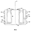
図2は、メス電気レセプタクル60の断面描画であり、断面は、図1の「A」と表された方向に沿って取られている。この実施形態において、レセプタクル60は、本体61に含まれる伝導性スリーブ205および210を有する。伝導性スリーブ205および210は、アパーチャ80およびアパーチャ90のそれぞれを通ってアクセス可能である(図1)。第3の伝導性スリーブ215は、図3に描かれる。伝導性スリーブ205、210および215(「描かれた伝導性スリーブ」)は、銅または真鍮などの伝導性金属から成る。描かれた伝導性スリーブは、二つ以上の金属部品をファスナーによって組合わせることによって作られ得る。スリーブ205および210の好適な実施形態は、二つの金属部品から作られる。
FIG. 2 is a cross-sectional depiction of the female
この実施形態において、スリーブ205および210は、伝導性接触通路206および211をそれぞれ有する。伝導性接触通路206および211(「接触」)は、各々、メスレセプタクル60の中心Cから離れた伝導性通路を形成する。伝導性接触通路206は、好適には、レセプタクル60の中心から離れて環状の接触12に向かって、少なくとも小距離を半径的に横切りまたは横切って延伸し、環状の接触12は、本実施形態において、レセプタクル60の外側の回りに配置される。別の実施形態は、レセプタクル60の中心に向かって配置された環状の伝導性接触を有し得、レセプタクル60はそのような接触のまわりを回転する。外側が好適である。接触206は、環状の接触12Cにスライド可能なように接触または寄りかかる。12Cのラベルのついた描画の二つのポーションは、同じ環状の接触12の反対のポーションである。この実施形態において、接触206は、伝導性スリーブ205から環状の接触12Cへの距離を放射状に横切って延伸する。そのような延伸は、直線の半径方向に向き得るかまたは向き得ない。接触206は、少なくとも部分的には、環状の接触12Cの垂直高さに配置される。
In this embodiment,
スリーブ210は、伝導性スリーブ210から環状の接触12Bに放射状に横切り、延伸する伝導性接触通路211を有する。そのような通路は、直接の放射方向に向き得るかまたは向き得ない。伝導性接触通路211は、メスレセプタクル60がその中心Cのまわりを回るとき、他の伝導性接触通路または環状のリングに対して機械的な妨害を避けるように考案される方法で、少なくとも部分的には、環状の接触12Bの垂直高さに配置される。好適には、そのような回転には制限はなく、レセプタクル60は、全360度回転され得る。好適には、スリーブ205および210は、伝導性接触通路206および211と共に、それらを構成する金属部品を曲げることによって、形成される。
The
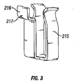
図3は、本発明の好適な実施形態に従った伝導性スリーブ215を描く。本実施形態において、伝導性スリーブ215は、アパーチャ100を通ってアクセス可能であり、典型的には、ソケット20の接地接続に対応する。伝導性スリーブ215は、レセプタクル60の中心Cから離れる半径距離を横切るように好適に配置される。この実施形態において、伝導性接触通路216は、上部環状の接触12Aの垂直高さにある(図2)。外側接触面217は、環状の接触12の内部のレセプタクル60の回転を可能にするように考案された方法で、環状の接触12Aにスライド可能に接触または寄りかかるように位置が定められる。
FIG. 3 depicts a
図4は、本発明の好適な実施形態に従ったメス電気レセプタクル60の上面図を描く。アパーチャ80および90は、プラグプロングを受けるために上方への伝導性スリーブ205および210において開口部を提供する。アパーチャ100は、同様に伝導性スリーブ215の開口上部を提供する。好適な実施形態において、図4に描かれた伝導性スリーブ205、210および215の露出したポーションを覆うように絶縁カバープレートが置かれる。
FIG. 4 depicts a top view of a female
図5は、本発明の好適な実施形態に従ったアウトレット20のハウジング40の下部ポーション502を描く。
FIG. 5 depicts a
図6は、図5に描かれたポーション502の断面描画であり、断面は「D」と表された方向に沿って取られている。
FIG. 6 is a cross-sectional drawing of the
図5および図6を参照すると、本実施形態におけるハウジングは、下部層がポーション502である層で構成される。ポーション502は、ハウジングキャビティ45Aおよび45Bの下部分を表し、そのキャビティは、フロア(floor)506を有する。キャビティ45Aおよび45Bの描かれたポーションは、各々、環状の伝導性接触12を保持するためのレッジ(ledge)510を有する。ライン602は、本実施形態において、ポーション502の中間にスロット504の存在を表示するために示される。キャビティ45Aは、環状の伝導性接触12Cがキャビティ45Aの壁の伝導性リングポーションを提供するように挿入された状態で描かれる。
Referring to FIGS. 5 and 6, the housing according to the present embodiment is composed of a layer whose portion is a
一代替の実施形態は、フロア506を有してなく、それによって、伝導性メンバが環状の伝導性接触12のより低いポーションへの接続を可能にする。
One alternative embodiment does not have a
本実施形態において、ポーション502は、その上部側に、伝導性メンバ902の挿入のために形成されるスロット504を有する(図9)。この実施形態において、伝導性メンバ902は、環状の伝導性接触12への電気的接続を形成し、電気的配線を取り付けるためのねじ穴904を提供する。構成の一好適なシーケンスにおいて、ポーション502は、形成され、次に、環状の伝導性接触12は、妨害がフィットする状態で挿入される。伝導性ポーション902は、環状の伝導性接触12にはんだづけまたは溶接される。伝導性ポーション902は、代わりに、妨害がフィットしている状態においてのみ接触12に接続され得、または、ポーション902はまた、接触12と共に一体として形成され得る。
In this embodiment, the
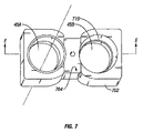
図7は、本発明の好適な実施形態に従ったアウトレット20のハウジング40のポーション702を描く。
FIG. 7 depicts a
図8は、図7に描かれたポーション702の断面描画であり、断面は「E」と表された方向に沿って取られている。
FIG. 8 is a cross-sectional depiction of the
図7および図8を参照すると、本実施形態におけるハウジング40は、二つの内部層が各々ポーション702に対して形成される状態で、層に構成される。ポーション702は、ハウジングキャビティ45Aおよび45Bの上部ポーションを表す。キャビティ45Aおよび45Bの描かれたポーションは、各々、環状の伝導性接触12を保持するためのレッジ710を有する。ポーション702は、その上部側に、伝導性メンバ902の挿入のために形成されるスロット704を有する(図9)。この実施形態において、伝導性メンバ902は、環状の伝導性接触12への電気的接続を形成し、電気的配線を取り付けるためのねじ穴904を提供する。構成の一好適なシーケンスにおいて、ポーション702は、形成され、次に、環状の伝導性接触12は、レッジ710においてフィットするように、妨害がフィットしている状態で挿入される。他の実施形態は、伝導性接触12を場所に接着またはさもなければ、固定する。
Referring to FIGS. 7 and 8, the
図9は、本発明の好適な実施形態に従った伝導性フィッティングを描く。 FIG. 9 depicts a conductive fitting according to a preferred embodiment of the present invention.
図10Aは、本発明の好適な実施形態に従った別の伝導性フィッティング1002を描く。 FIG. 10A depicts another conductive fitting 1002 according to a preferred embodiment of the present invention.
図10Bは、本発明の代替の実施形態に従った別の伝導性フィッティング1004を描く。この実施形態において、環状の伝導性接触12は、伝導性フィティング1004と一体に組み合わされる。伝導性フィティング1004は、下部ポーション502の上のスロット504にはめ込まれる。スロット504もまた、伝導性フィッティング1004が、電気配線を取り付けるためのねじ穴1006を提供するために、ポーション502の下に延伸することを可能にするように考案された方法で、下部ポーション502の下に位置が定められ得る。
FIG. 10B depicts another conductive fitting 1004 according to an alternative embodiment of the present invention. In this embodiment, the annular
図11は、本発明の好適な実施形態に従った上部伝導性プレート1102を描く。プレート11は、電気配線のねじ取り付けのための接触1104を有する。
FIG. 11 depicts an upper
前の図を参照すると、本発明に従ったソケット20をアセンブリする一好適なシーケンスは、次のとおりである。下部ポーション502は、スロット504に置かれた伝導性メンバ902に接続された環状の伝導性接触12Cが備えつけられる。第1ポーション702は、下部ポーション502の上に置かれ、環状の伝導性接触12Bが備えつけられる。伝導性メンバ902は、環状の伝導性接触12Bと電気的に接続され、スロット704に置かれる。第2のポーション702は、第1ポーション702の上に置かれ、環状の伝導性接触12Aが備えつけられる。伝導性メンバ1002は、環状の伝導性接触12Aと電気的に接続され、第2のポーションのスロット704に置かれる。そのような接続は、ハウジングキャビティを形成するように整列されるポーション502および702の各々の開口部45Aおよび45Bを有するハウジングを形成する。
Referring to the previous figure, one preferred sequence for assembling the
第1および第2のメス電気レセプタクルアセンブリ60は、ハウジングキャビティ45Aおよび45Bの中にそれぞれ置かれる。それぞれの電気的接続は、図2に描かれているように、アセンブリ60および環状の伝導性リング上の接触間になされる。次に、上部伝導性プレート1102は、伝導性メンバ1002と電気的に接続され、アセンブリされたソケットの上に置かれる。
First and second female
本発明の描かれた実施形態において採用される種々の伝導性コンポーネントは、好適には真鍮製である。しかしながら、この目的のために任意の適切な伝導性材料が使用され得ることは、当業者は認識する。例えば、真鍮、銅、鋼合金、およびその他の合金を使用することは、広く認められる。本発明の描かれた実施形態の採用された不伝導性コンポーネントは、プラスチックおよびポリ塩化ビニル(PVC)を含む任意の不伝導性または絶縁材料製であり得る。再び、任意の適切な不伝導性または絶縁材料が採用され得ることを当業者は理解する。本説明の明快さのため、単純な例示的リオリエンタブル電気アウトレット20が例示される。但し、本明細書に記述されたリオリエンタブル電気アウトレット20は、種々のモデル、コンフィギュレーションに適応でき、メス電気レセプタクルおよびアダプタの多くのその他のタイプを含むように考案され得ることは当業者は理解する。例えば、本発明は、固定ソケットをリオリエンタブル手段に変換するように考案されたアダプタにおいて実施され得る。
The various conductive components employed in the depicted embodiments of the present invention are preferably made of brass. However, those skilled in the art will recognize that any suitable conductive material can be used for this purpose. For example, the use of brass, copper, steel alloys, and other alloys is widely accepted. The employed non-conductive components of the depicted embodiments of the present invention can be made of any non-conductive or insulating material including plastic and polyvinyl chloride (PVC). Again, those skilled in the art will appreciate that any suitable non-conductive or insulating material may be employed. For clarity of this description, a simple exemplary lioretable
メス電気レセプタクルの数、形状、および構造は、単に例であり、本発明の採用のために必要な設計制限として解釈されるべきではない。例えば、メス電気レセプタクル60Aおよび60Bは、接地および非接地の両方の典型的な住宅用レセプタクルからテーブルタップ、220Vレセプタクル、および2、3、4またはそれ以上のプロング受け設計を含む480Vレセプタクルまでの広い範囲に広がっている。これらのデバイスは、種々のオスプラグのプロングがメスの電気レセプタクルに挿入されること、および任意の所望の位置に回転されることを可能にし得、それによって、他のオスプラグまたは任意の所定のオスプラグが隣接するメス電気レセプタクルの中への使用を不可能にし得るその他の制限に関して妨害しない位置に定めることを可能にする。
The number, shape, and structure of the female electrical receptacles are merely examples and should not be construed as necessary design limitations for employing the present invention. For example, female
本発明の代替の実施形態において、メス電気レセプタクルは、例示的無極オスプラグの従来の電力および共通プロングの挿入のために方向を合わせられ、反対に配置されたアパーチャのみを含むように考案され得る。メス電気レセプタクルのそのような2プロングオスプラグ受け設計は、3プロングオスプラグ受けの好適な実施形態の場合に存在する接地プロングが無いことによる構造コンポーネントを支持する外側の同心の環状の伝導性を必要としない。 In an alternative embodiment of the present invention, a female electrical receptacle can be devised to include only apertures oriented and oppositely oriented for the insertion of the conventional power and common prongs of an exemplary non-polar male plug. Such a two-prong male plug receptacle design of the female electrical receptacle provides an outer concentric annular conductivity that supports structural components due to the absence of ground prongs present in the preferred embodiment of the three-prong male plug receptacle. do not need.
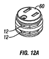
図12Aは、本発明の別の実施形態に従ったメス電気レセプタクル60を描く。
FIG. 12A depicts a female
図12Bは、図12Aのメス電気レセプタクル60の分解図を描く。図12Aおよび図12Bを参照すると、この実施形態において、メス電気レセプタクル60は、環状の伝導性接触12を有する。分割された接触12は、八角形の真鍮フィッティングとして実施される。この実施形態において、レセプタクル60は、2個の環状の伝導性接触12のみを有する。上部の描かれた接触12は、伝導性スリーブ205に接続される。伝導性スリーブ205のポーションは、逆さL形を有し、それぞれのスリーブ12へ放射状に横切る伝導性通路を提供する。下部の描かれた接触12は、伝導性スリーブ210に接続される。伝導性スリーブ205のポーションは、L形を有し、下部スリーブ12へ放射状に横切る伝導性通路を提供する。
FIG. 12B depicts an exploded view of the female
この実施形態において、中央サポートポーション1202は、描かれたスロットへ挿入された伝導性スリーブ205、210および215ならびにレッジ1208に隣接する環状の伝導性接触12と共にアセンブリされる。下部ポーション1204は、下部の描かれた接触12を適切な場所にロックするために、中央サポートポーション1202にフィットする。同様に、スロットキャップ1206は、上部の描かれた接触12を適切な場所にロックするために、中央サポートポーション1202にフィットする。この実施形態において、スリーブ215は、導体1304に電気的に接続するための下部接触ポーション1210を有する(図13)。
In this embodiment, the
図13は、本発明の代替の実施形態に従ったハウジング40を描く。接触1302は、回転可能なレセプタクル60を受けるように考案される。この実施形態において、接触1302および環状の接触12は、その周囲にまっすぐにされたセクションを有するように考案される。これらの描かれたまっすぐのセクションは、ある整列された方向においてレセプタクル60の回転動作の限度を提供するためのストッパとして働き得る。そのようなストッパは、また、例えば、刻み目または高くなったバンプ(bump)または他の特徴を置くことによって達成され得る。接触1302は、ねじ1306に取り付けられた線への電流をサポートするように考案された方法で、選択されたねじ1306に電気的に接続される。導体1304は、好適には、接地線を受ける。
FIG. 13 depicts a
図14は、本発明の一実施形態に従ってレセプタクル60がハウジング40にはめ込まれる方法のアウトレット20の分解図を描く。一般に、レセプタクル60は、伝導性接触1302の中に収容される。各レセプタクル60に関して、伝導性接触1302は、好適には電力の異なる極性を伝える。例えば、上部の描かれた接触1302は、レセプタクル60のホットライン電圧を伝え得、一方、下部の描かれた接触1302は、レセプタクル60の中立ライン電圧を伝え得る。
FIG. 14 depicts an exploded view of the
図15は、本発明の別の代替の実施形態に従った別のメス電気レセプタクル60を描く。この実施形態において、レセプタクル60は、伝導性スリーブ205および210を受けるためのスロット1502を有する。スリーブ205および210の各々は、好適には、スプリングポーションを形成するように形作られた伝導性接触通路1504を有する。スプリングポーションは、回転に対する抵抗を生成するために環状の伝導性接触12に対して押圧するかまたは接触する。そのような抵抗は、例えば、接触通路1502上のバンプポーションおよび/または環状の伝導性接触12上のバンプポーションなどの停止特徴の使用によってさらに強化され得る。
FIG. 15 depicts another female
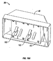
図16Aおよび図16Bは、本発明の別の実施形態に従ったアウトレットを描く。図16Aは、下部立面図である。図16Bは、上部立面図である。この実施形態において、拡張アウトレット20は、壁プラグまたはその他の電気アウトレットへの接続のためのプラグ162が備えつけられている。3プロングの米国標準プラグが示されているが、他のプラグは、もちろん、使用され得る。プラグ162のプロングは、4拡張プラグレセプタクルを提供するように考案される類似の方法で、レセプタクル60A〜60Dの接触に並行して好適に接続される。描かれたアウトレットは、壁アウトレットフェースプレートを覆ってはめこまれ、確実な機械的支持を提供するように考案されたリップ161を有する。他の実施形態は、他の種類の取り付け具にはめこむように考案され得る。2プラグ〜4プラグ拡張アウトレットが示されるが、他の数のプラグ、例えば、1プラグ〜4プラグアウトレットなどは、もちろん、使用され得る。
16A and 16B depict an outlet according to another embodiment of the present invention. FIG. 16A is a bottom elevation view. FIG. 16B is a top elevation view. In this embodiment, the
図17は、本発明の別の実施形態に従ったアウトレットの分解図を示す。アウトレット20は、積み重ねてはめこまれ、まとめてねじ止めされアウトレット20を作成するフェースプレートポーション35およびいくつかの部品171〜178を有するプレート30を含む。ハウジングキャビティ45は、バッキング部品178以外の描かれたすべての部品を通って延伸する。メス電気レセプタクルは、図1〜図2に関して記述された方法と同様な方法で、ハウジングキャビティ45にはめこまれる。
FIG. 17 shows an exploded view of an outlet according to another embodiment of the present invention. The
プレート30の下に描かれているのは、絶縁層部品174である。部品174の下は、伝導性はめこみ部品171であり、図5〜6に関して記述された方法と同様な方法で、部品絶縁層部品175にはめこまれるように設計される。描かれた部品175は、4つの環状の接触12にはめこまれ、部品175の穴45にはめこまれる。穴45は、レッジ510を有し、該レッジ510は、各環状の接触を支持し、部品175の下の伝導性はめこみ部品172上の環状の接触からの絶縁分離を提供する。伝導性はめこみ部品172は、絶縁層部品176に同様に配置される。
Depicted below the
この実施形態において、最下に描かれる伝導性はめこみ部品173は、絶縁層部品177に置かれる。この実施形態において、部品177は、レッジ512を有しないで、代わりに、バッキング部品178上にある部品173の環状の接触12を有する。この実施形態において、伝導性はめこみ部品は環状の接触12を有し、該環状の接触の上部は平部品によって接続されているが、他の実施形態は、4つの環状の接触12を、例えば、環状の接触12の下部に接続されたプレートなどと一緒に接続するための他の構造を有し得る。
In this embodiment, the
さらに図17を参照すると、伝導性はめこみ部品171〜173は、各々、プラグ162A〜Cを形成するためのプロング162A〜Cを有する。プロング162A〜Cは、描かれた穴を通って、種々の絶縁層部品およびバッキング部品178に突き出る。好適には、プロング162は、描かれた部品がアセンブリされるとき、バッキング178の外側に均一または所望のプロング長を有するプラグを作成するようにスタッガードの長さを有し得る。
Still referring to FIG. 17, conductive inset components 171-173 have
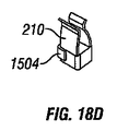
図18A〜図18Eは、別の実施形態に従ったメス電気レセプタクルの分解された部品を描く。描かれた部品は、図15に示された部品と同様である。伝導性接触スリーブ205、210および215は、下部部品182にはめこまれるように考案される。次に、上部部品181は、接触スリーブを覆うようにはめこまれる。次に、スプリングポーション1504は、レセプタクルがハウジングキャビティ45の中に挿入されるとき、スプリングポーション1504が伝導性スリーブ12に接触するように、アセンブリされたレセプタクルの外側に沿って3つの異なる高さで配置される。
18A-18E depict disassembled parts of a female electrical receptacle according to another embodiment. The depicted parts are similar to the parts shown in FIG.
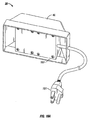
図19Aおよび図19Bは、本発明の別の実施形態に従ったアウトレットを描く。図19Aは下部立面図である。図19Bは上部立面図である。この実施形態において、アウトレット20は、図16Bに示されるものと同様な4つの回転可能なプラグレセプタクルが備えつけられる。この実施形態は、ハウジング40に取りつけられた固定プラグよりはむしろ、延長コードプラグ191を有する。
19A and 19B depict an outlet according to another embodiment of the present invention. FIG. 19A is a bottom elevation view. FIG. 19B is a top elevation view. In this embodiment,
当業者は、この仕様を理解した後に理解するように、本明細書の発明コンセプトは、種々のアプリケーションにおいて使用され得る。例えば、本明細書に記述された回転可能なアウトレットおよび拡張アウトレットは、任意の電圧規格およびプラグ設計と共に使用されるように作られ得る。さらに、例えば、リセットまたはテストボタンを有する接地事故回路インタラプタ(GFCI)を有する接地事故インタラプト(GFI)アウトレットは、本明細書に記述されるコンセプトと組み合わせて使用され得、種々の数のレセプタクルを有する種々のパワーストリップ設計が使用され得る。 As those skilled in the art will appreciate after understanding this specification, the inventive concepts herein can be used in a variety of applications. For example, the rotatable outlets and expansion outlets described herein can be made to be used with any voltage standard and plug design. Further, for example, a ground fault interrupt (GFI) outlet having a ground fault circuit interrupter (GFCI) with a reset or test button can be used in combination with the concepts described herein and has various numbers of receptacles. Various power strip designs can be used.
図20は、本発明の別の実施形態に従った環状の伝導性接触12を描く。この実施形態において、接触12は、絶縁ポーション202を有し、該絶縁ポーション202は、電力がアウトレットに供給されない「オフ」位置を提供するために使用される。オフ位置は、レセプタクルを直立位置から最も遠くのオフ軸方向に回すことによって、好適に達成される。他の実施形態は、傾斜した円形の接触12を有し得、該接触12は、アクティブポーションの下に絶縁ポーション202を提供し、直立「オフ」位置および直立「オン」位置を可能にする。
FIG. 20 depicts an annular
この実施形態において、絶縁ポーション202は、絶縁されたオフ位置において211および206のような伝導性接触通路を確保するためのバンプポーション204を有する。バンプポーション204は、また、レセプタクルが「オフ」位置になっているという触知できるフィードバックを提供し得る。さらに、アウトレット20の前面のインジケータウィンドウは、色づけされたタブ、または、レセプラクルが「オフ」位置になっているという他の表示信号を提供し得る。その他の実施形態は、レセプタクルをオフ位置にするためのスイッチを採用し得る。
In this embodiment, the
絶縁ポーション202は、金属伝導性接触12の全体に絶縁コーティングを使用してインプリメントされ得、または、例えば、間隙および堅固な絶縁構造などの電気的絶縁を提供するための他の構造またはそのような構造の組み合わせであり得る。
Insulating
本明細書の実施形態は、詳細に記述されているが、種々の特定の形式をとり、変更、代替、修正を表す多くの実施形態は、本発明の精神と範囲を逸脱することなく、なされ得ることは、当業者にとって明らかである。記述された実施形態は、特許請求の範囲の範囲を例示するが、特許請求の範囲を制限するものではない。 Although the embodiments herein have been described in detail, many embodiments that take various specific forms and represent changes, substitutions, and modifications can be made without departing from the spirit and scope of the invention. It will be apparent to those skilled in the art that The described embodiments illustrate the scope of the claims, but do not limit the scope of the claims.
Claims (43)
固定ハウジングと、
互いに電気的に絶縁された第1および第2の電気伝導性スリーブを有する電気レセプタクルと、
該メス電気レセプタクルを受けるために該固定ハウジングに配置されたハウジングキャビティであって、該ハウジングキャビティは、第1および第2の環状の電気伝導性通路が上下にあるように配置された実質的に円形の壁を有する、ハウジングキャビティと、
該第1および第2の電気スリーブを、それぞれ、該第1および第2の環状の電気伝導性通路に接続する伝導性通路と
を備える、リオリエンタブル電気アウトレット。 Reorientable electric outlet,
A fixed housing;
An electrical receptacle having first and second electrically conductive sleeves that are electrically isolated from each other;
A housing cavity disposed in the stationary housing for receiving the female electrical receptacle, wherein the housing cavity is substantially disposed with the first and second annular electrically conductive passages above and below. A housing cavity having a circular wall;
A conductive passage connecting the first and second electrical sleeves to the first and second annular electrical conductive passages, respectively.
該第3の電気伝導性スリーブと電気的に通信する第3の伝導性通路と
をさらに備える、請求項1に記載のリオリエンタブル電気アウトレット A third electrically conductive sleeve electrically insulated from the first and second electrically conductive sleeves;
The lioretable electrical outlet of claim 1, further comprising: a third conductive passage in electrical communication with the third electrically conductive sleeve.
二つの環状の伝導性接触に対して二つの環状の電気接触をスライドさせるステップであって、該二つの環状の伝導性接触は上下に置かれる、ステップ
を包含する、方法。 A method of rotating an electrical plug in a socket, the method comprising:
Sliding the two annular electrical contacts against the two annular conductive contacts, the two annular conductive contacts being placed one above the other.
固定ハウジングと、
第1および第2のメス電気レセプタクルアセンブリであって、各メスレセプタクルアセンブリは、互いに電気的に絶縁された第1および第2の電気伝導性スリーブを有し、第1の伝導性通路は、該第1の電気伝導性スリーブに接続され、該第1の伝導性通路は、該メス電気レセプタクルアセンブリに対して少なくとも部分的に放射状に延伸し、第2の伝導性通路は、該第2の電気伝導性スリーブに接続され、該第2の伝導性通路は、該メス電気レセプタクルアセンブリに対して少なくとも部分的に放射状に延伸する、第1および第2のメス電気レセプタクルアセンブリと、
該第1および第2のメス電気レセプタクルアセンブリを受けるために該固定ハウジングに配置された第1および第2のハウジングキャビティであって、該第1および第2のハウジングキャビティは、各々、第1および第2の環状の伝導性通路を有し、該環状の伝導性通路に対して該第1および第2の伝導性通路が、それぞれ、配置され、該第1および第2のメス電気アセンブリは、該第1および第2のハウジングキャビティにおいてそれぞれ回転可能であり、該第1および第2の伝導性通路を該第1および第2の環状の伝導性通路に接触してスライド可能なように維持する、第1および第2のハウジングキャビティと
を備える、リオリエンタブル電気アウトレット。 Reorientable electric outlet,
A fixed housing;
First and second female electrical receptacle assemblies, each female receptacle assembly having first and second electrically conductive sleeves that are electrically isolated from each other, wherein the first electrically conductive passages include Connected to a first electrically conductive sleeve, the first conductive passage extending at least partially radially with respect to the female electrical receptacle assembly, and a second conductive passage extending to the second electrically conductive sleeve; First and second female electrical receptacle assemblies connected to a conductive sleeve and wherein the second conductive passage extends at least partially radially with respect to the female electrical receptacle assembly;
First and second housing cavities disposed in the stationary housing to receive the first and second female electrical receptacle assemblies, wherein the first and second housing cavities are respectively first and second A second annular conductive passage, wherein the first and second conductive passages are disposed relative to the annular conductive passage, respectively, and the first and second female electrical assemblies include: Rotating in the first and second housing cavities, respectively, and maintaining the first and second conductive passages in contact with and sliding on the first and second annular conductive passages. A lioretable electrical outlet comprising: a first and a second housing cavity.
露出した表面と、
前記第1および第2の電気伝導性スリーブに整列された該露出した表面を通る第1および第2のアパーチャであって、オスプラグの第1および第2のプロングが該第1および第2のアパーチャをそれぞれ通って延伸し、該第1および第2の電気伝導性スリーブと電気的接触を得ることを可能にする、第1および第2のアパーチャと
をさらに備える、請求項12に記載のリオリエンタブル電気アウトレット。 The first and second female electrical receptacles are:
Exposed surface,
First and second apertures through the exposed surfaces aligned with the first and second electrically conductive sleeves, wherein the first and second prongs of the male plug are the first and second apertures; The first and second apertures, respectively, extending through each of the first and second electrically conductive sleeves to allow electrical contact with the first and second electrically conductive sleeves. Bull electric outlet.
該第3の電気伝導性スリーブと電気的に通信する第3の伝導性通路と
をさらに備える、請求項12に記載のリオリエンタブル電気アウトレット。 A third electrically conductive sleeve electrically insulated from the first and second electrically conductive sleeves;
The lioretable electrical outlet of claim 12, further comprising: a third conductive passage in electrical communication with the third electrically conductive sleeve.
露出した表面と、
前記第1、第2のおよび第3の電気伝導性スリーブに整列された該露出した表面を通る第1、第2および第3のアパーチャは、オスプラグの第1、第2および第3のプロングが該第1、第2および第3のアパーチャをそれぞれ通って延伸し、該第1、第2および第3の電気伝導性スリーブと電気的接触を得ることを可能にする、第1、第2および第3のアパーチャと
をさらに備える、請求項12に記載のリオリエンタブル電気アウトレット。 The first and second female electrical receptacles are:
Exposed surface,
The first, second and third apertures through the exposed surfaces aligned with the first, second and third electrically conductive sleeves are connected to the first, second and third prongs of the male plug. First, second and third, respectively, extending through the first, second and third apertures, allowing electrical contact with the first, second and third electrically conductive sleeves; The lioretable electrical outlet of claim 12, further comprising: a third aperture.
固定ハウジングと、
二つ以上のメス電気レセプタクルであって、各メス電気レセプタクルは、互いに電気的に絶縁された第1および第2の電気伝導性スリーブを有する、二つ以上のメス電気レセプタクルと、
該メス電気レセプタクルをそれぞれ受けるように該固定ハウジングに配置された二つ以上のハウジングキャビティであって、該ハウジングキャビティは各々実質的に円形の壁を有し、該壁に沿って第1および第2の環状の伝導性通路が上下に配置される、二つ以上のハウジングキャビティと、
該メス電気レセプタクルの各々の該第1および第2の電気スリーブを該ハウジングキャビティのそれぞれの第1および第2の環状の伝導性通路のそれぞれに接続する伝導性通路と、
壁アウトレットに接続するように適合された第1および第2の電気プロングを有する電気プラグであって、該第1および第2の電気プロングは、各ハウジングキャビティの該第1および第2の環状の伝導性通路のそれぞれに並行して電気的に接続される、電気プラグと
を備える、リオリエンタブル電気拡張アウトレット。 Reorientable electrical expansion outlet,
A fixed housing;
Two or more female electrical receptacles, each female electrical receptacle having two and more female electrical receptacles having first and second electrically conductive sleeves that are electrically isolated from each other;
Two or more housing cavities disposed in the stationary housing to each receive the female electrical receptacle, the housing cavities each having a substantially circular wall, the first and the second along the wall; Two or more housing cavities in which two annular conductive passages are arranged one above the other;
A conductive passage connecting the first and second electrical sleeves of each of the female electrical receptacles to a respective first and second annular conductive passage of the housing cavity;
An electrical plug having first and second electrical prongs adapted to connect to a wall outlet, wherein the first and second electrical prongs are the first and second annular prongs of each housing cavity. A lioretable electrical extension outlet comprising: an electrical plug electrically connected in parallel to each of the conductive passages.
をさらに備える、請求項24に記載のリオリエンタブル電気アウトレット。 In each female electrical receptacle, a third electrically conductive sleeve electrically insulated from the first and second electrically conductive sleeves, and a third electrically conductive sleeve in electrical communication with the third electrically conductive sleeve 25. The lioretable electrical outlet of claim 24, further comprising a conductive passage.
ハウジングと、
該固定ハウジングに配置された第1および第2のハウジングキャビティであって、該第1および第2のハウジングキャビティは、環状の領域を各々規定する第1および第2の環状の伝導性通路を各々有する、第1および第2のハウジングキャビティと、
該第1および第2のハウジングキャビティにそれぞれ少なくとも部分的に挿入されるように適合された第1および第2のメス電気レセプタクルアセンブリであって、各メスレセプタクルアセンブリは、互いに電気的に絶縁された第1および第2の電気伝導性スリーブならびに該第1および第2環状の伝導性通路によってそれぞれ規定される環状の領域の内部に部分的に配置される第1および第2の伝導性接触を有し、該第1および第2の伝導性接触は、該第1および第2の環状の伝導性通路に対して部分的に配置される第1および第2のスプリングメンバをそれぞれ有し、該第1および第2のメス電気アセンブリは、該第1および第2ハウジングキャビティにおいてそれぞれ回転可能であり、一方、該第1および第2のスプリングメンバが該第1および第2の環状の伝導性通路に接触することをスライド可能なように維持する、第1および第2のメス電気レセプタクルアセンブリと、
壁アウトレットに接続するように適合された第1および第2の電気プロングを有する電気プラグであって、該第1および第2の電気プロングは、各ハウジングキャビティの該第1および第2の環状の伝導性通路のそれぞれに並行して電気的に接続される、電気プラグと
を備える、リオリエンタブル電気拡張アウトレット。 Reorientable electrical expansion outlet,
A housing;
First and second housing cavities disposed in the stationary housing, wherein the first and second housing cavities each define first and second annular conductive passages that each define an annular region; Having first and second housing cavities;
First and second female electrical receptacle assemblies adapted to be at least partially inserted into the first and second housing cavities, respectively, each female receptacle assembly being electrically isolated from one another; First and second electrically conductive sleeves and first and second conductive contacts disposed partially within an annular region defined by the first and second annular conductive passages, respectively. And the first and second conductive contacts have first and second spring members, respectively, partially disposed with respect to the first and second annular conductive passages, The first and second female electrical assemblies are rotatable in the first and second housing cavities, respectively, while the first and second spring members are Maintaining to allow slide to contact the first and second annular conductive path, and the first and second female electrical receptacle assembly,
An electrical plug having first and second electrical prongs adapted to connect to a wall outlet, wherein the first and second electrical prongs are the first and second annular prongs of each housing cavity. A lioretable electrical extension outlet comprising: an electrical plug electrically connected in parallel to each of the conductive passages.
前記第1および第2の電気伝導性スリーブから電気的に絶縁された第3の電気伝導性スリーブと、
該第3の電気伝導性スリーブと電気的に通信する第3の伝導性接触と
をさらに備える、請求項32に記載のリオリエンタブル電気アウトレット。 Each female electrical assembly
A third electrically conductive sleeve electrically insulated from the first and second electrically conductive sleeves;
33. A liotable electric outlet according to claim 32, further comprising: a third conductive contact in electrical communication with the third electrically conductive sleeve.
露出した表面と、
前記第1、第2および第3の電気伝導性スリーブに整列された該露出した表面を通る第1、第2および第3のアパーチャであって、オスプラグの第1、第2および第3のプロングが該第1、第2および第3のアパーチャをそれぞれ通って延伸し、該第1、第2および第3の電気伝導性スリーブと電気的接触を得ることを可能にする、第1、第2および第3のアパーチャと
をさらに備える、請求項32に記載のリオリエンタブル電気アウトレット。 The first and second female electrical receptacles are:
Exposed surface,
First, second, and third apertures of the male plug through the exposed surfaces aligned with the first, second, and third electrically conductive sleeves, the first, second, and third prongs of the male plug Extending through the first, second and third apertures, respectively, allowing to make electrical contact with the first, second and third electrically conductive sleeves 33. The lioretable electrical outlet of claim 32, further comprising: and a third aperture.
上下に配置された二つ以上の環状の伝導性経路を備えるハウジングと、
電気レセプタクルであって、該電気レセプタクルは、それぞれの環状の伝導性通路に対して各々配置された二つ以上のスプリング様の接触を有し、該電気レセプタクルは、該ハウジングに対して少なくとも部分的に回転可能である、電気レセプタクルと、
該環状の伝導性通路に電気的に接続された電気プラグであって、該電気プラグは該拡張アウトレットを別の電気アウトレットに接続するように適合された、電気プラグと
を備える、電気拡張アウトレット。 An electrical expansion outlet,
A housing comprising two or more annular conductive paths disposed one above the other;
An electrical receptacle, the electrical receptacle having two or more spring-like contacts, each disposed with respect to a respective annular conductive passage, wherein the electrical receptacle is at least partially with respect to the housing; An electrical receptacle that is rotatable,
An electrical expansion outlet comprising: an electrical plug electrically connected to the annular conductive passage, the electrical plug adapted to connect the expansion outlet to another electrical outlet.
Applications Claiming Priority (3)
| Application Number | Priority Date | Filing Date | Title |
|---|---|---|---|
| US10/996,106 US7125256B2 (en) | 2004-11-23 | 2004-11-23 | Reorientable electrical outlet |
| US11/081,282 US7121834B2 (en) | 2004-11-23 | 2005-03-16 | Reorientable electrical receptacle |
| PCT/US2005/012673 WO2006057661A1 (en) | 2004-11-23 | 2005-04-14 | Reorientable electrical receptacle |
Publications (1)
| Publication Number | Publication Date |
|---|---|
| JP2008521202A true JP2008521202A (en) | 2008-06-19 |
Family
ID=36461481
Family Applications (1)
| Application Number | Title | Priority Date | Filing Date |
|---|---|---|---|
| JP2007543014A Pending JP2008521202A (en) | 2004-11-23 | 2005-04-14 | Reorientable electrical receptacle |
Country Status (6)
| Country | Link |
|---|---|
| US (2) | US7125256B2 (en) |
| JP (1) | JP2008521202A (en) |
| CN (1) | CN1780071A (en) |
| CA (1) | CA2586652C (en) |
| MX (1) | MX2007006087A (en) |
| WO (1) | WO2006057661A1 (en) |
Cited By (3)
| Publication number | Priority date | Publication date | Assignee | Title |
|---|---|---|---|---|
| CN102882094A (en) * | 2012-10-25 | 2013-01-16 | 浙江大学 | Rotatable wiring board of single socket |
| JP5180401B1 (en) * | 2012-09-13 | 2013-04-10 | 株式会社アドバーンス企画 | Recessed power outlet |
| WO2020166275A1 (en) * | 2019-02-13 | 2020-08-20 | 日本航空電子工業株式会社 | Connector |
Families Citing this family (30)
| Publication number | Priority date | Publication date | Assignee | Title |
|---|---|---|---|---|
| US7500854B2 (en) * | 2005-11-02 | 2009-03-10 | Gottstein M Peter | Electrical power distribution apparatus having a rotatable socket |
| US7666010B2 (en) * | 2006-10-27 | 2010-02-23 | Leviton Manufacturing Company, Inc. | Modular wiring system with locking elements |
| WO2008125118A1 (en) * | 2007-04-11 | 2008-10-23 | Tell It Online Aps | An electrical outlet system for distributing electrical power |
| CN201118055Y (en) * | 2007-10-13 | 2008-09-17 | 东莞欧陆电子有限公司 | Multi-size plug/socket power converter |
| US7435091B1 (en) * | 2007-12-18 | 2008-10-14 | Felix Cruz | Rotating electrical power plug adapter |
| US20140259651A1 (en) * | 2009-05-04 | 2014-09-18 | Nicholas Fletcher | Socket switch |
| US7824196B1 (en) | 2009-07-17 | 2010-11-02 | Hubbell Incorporated | Multiple outlet electrical receptacle |
| US20110124233A1 (en) * | 2009-11-23 | 2011-05-26 | Ernest Jerold Case | Method and apparatus for power supply connection |
| CN102694324B (en) * | 2011-04-19 | 2014-09-03 | 东莞维升电子制品有限公司 | Arbitrarily rotatable connecting structure and socket |
| US9028274B2 (en) | 2011-04-27 | 2015-05-12 | Quirky, Inc. | Reconfigurable plug strip |
| US8262399B1 (en) | 2011-04-27 | 2012-09-11 | Quirky Incorporated | Reconfigurable plug strip |
| USD701169S1 (en) | 2011-07-13 | 2014-03-18 | Quirky, Inc. | Reconfigurable plug adapter |
| US8500492B2 (en) | 2011-10-20 | 2013-08-06 | Quirky Incorporated | Reconfigurable plug adapter |
| US8439692B1 (en) | 2011-11-01 | 2013-05-14 | Hubbell Incorporated | Bus bar arrangements for multiple outlet electrical receptacles |
| US20140199883A1 (en) * | 2013-01-14 | 2014-07-17 | Mark Medley | Reversed Plug Orientation |
| US11011878B1 (en) | 2014-04-25 | 2021-05-18 | Jeffrey P. Baldwin | Electrical receptacle with prong receptacles within a front plate thickness |
| US9502808B1 (en) | 2014-04-25 | 2016-11-22 | Jeffrey Baldwin | Linear locking electrical device |
| WO2015168221A1 (en) | 2014-04-29 | 2015-11-05 | Bretford Manufacturing, Inc. | Recessed power system |
| US10320137B2 (en) * | 2016-01-06 | 2019-06-11 | Alon Almouli | Continuously rotatable plug |
| US9960524B2 (en) * | 2016-02-16 | 2018-05-01 | Sigma Electric Manufacturing Corporation | Slim line while in use cover and methods for making and using the same |
| TWI644488B (en) * | 2017-08-07 | 2018-12-11 | 勝德國際研發股份有限公司 | Rotatable socket device and socket module thereof |
| CN107658625A (en) * | 2017-10-23 | 2018-02-02 | 温州金樽家具有限公司 | A kind of multifunction rotary disc |
| US10033144B1 (en) * | 2017-11-08 | 2018-07-24 | Brenda Patterson | Electrical outlet having rotatable receptacles |
| CN111082273B (en) * | 2018-10-19 | 2021-05-25 | 南宁富桂精密工业有限公司 | Rotary socket |
| USD910573S1 (en) | 2018-11-06 | 2021-02-16 | Halo International SEZC Ltd. | Portable power strip |
| US10483068B1 (en) | 2018-12-11 | 2019-11-19 | Eaton Intelligent Power Limited | Switch disconnector systems suitable for molded case circuit breakers and related methods |
| US12418144B1 (en) | 2021-12-29 | 2025-09-16 | Titan3 Technology LLC | Gripping electrical receptacle |
| CN119318080A (en) * | 2022-06-16 | 2025-01-14 | 达伦·李·罗 | Power outlet |
| TWI837807B (en) * | 2022-09-05 | 2024-04-01 | 品威電子國際股份有限公司 | Electrical connector assembly and base thereof |
| WO2025097207A1 (en) * | 2023-11-06 | 2025-05-15 | Michael Edmund Gary Holt | Electrical power board |
Citations (3)
| Publication number | Priority date | Publication date | Assignee | Title |
|---|---|---|---|---|
| JPH02138888A (en) * | 1988-11-18 | 1990-05-28 | Fujitsu Ltd | Positional information system |
| JPH02141986A (en) * | 1988-11-24 | 1990-05-31 | Hitachi Ltd | Tape count detection device |
| JP2001189183A (en) * | 2000-01-06 | 2001-07-10 | Ricoh Co Ltd | Current collector |
Family Cites Families (31)
| Publication number | Priority date | Publication date | Assignee | Title |
|---|---|---|---|---|
| US1098501A (en) * | 1912-05-20 | 1914-06-02 | Mary E Holdaway | Electric-wire connection. |
| US2134355A (en) * | 1934-07-09 | 1938-10-25 | Eby Inv S Inc | Swivel electrical connection |
| US2288259A (en) * | 1939-08-03 | 1942-06-30 | Gladulich Ricardo | Connecting device for electrical conductors |
| US2459032A (en) * | 1946-10-03 | 1949-01-11 | Sam W Levine | Electrical connector |
| US2582800A (en) * | 1946-11-22 | 1952-01-15 | Jesse F Sorenson | Swiveling device for electric current |
| US2898572A (en) * | 1954-08-30 | 1959-08-04 | Henry L Shinn | Swiveling electrical connector |
| US3321728A (en) * | 1964-08-13 | 1967-05-23 | Bell Telephone Labor Inc | Rotating electrical connector for armored cord |
| US3437976A (en) * | 1967-05-11 | 1969-04-08 | Russell A Nelson | Swiveling connector for electric cord |
| US3771106A (en) * | 1971-04-14 | 1973-11-06 | New Nippon Electric Co | Socket suited for revolving the lamp attached thereto |
| US3975075A (en) * | 1974-09-18 | 1976-08-17 | Dracon Industries | Unitary offset wall plug |
| BE831559A (en) * | 1975-07-18 | 1975-11-17 | Faco Sa | ANTI-TWISTING DEVICE FOR ELECTRICAL CONNECTION |
| US4026618A (en) * | 1975-12-31 | 1977-05-31 | Straka Robert J | Low profile electrical male plug |
| US4520239A (en) * | 1982-09-30 | 1985-05-28 | Cable Electric Products, Inc. | Electrical cord reel and storage system |
| US4583798A (en) * | 1985-05-20 | 1986-04-22 | Blazowich Daniel L | Rotatable electrical connector |
| US4927376A (en) * | 1989-05-17 | 1990-05-22 | Paige Manufacturing Company Incorporated | Electrical plug assembly and system |
| US5352122A (en) * | 1992-12-15 | 1994-10-04 | Speyer Henning J | Rotatable electrical connector |
| US5425645A (en) * | 1993-11-19 | 1995-06-20 | Remington Products Company | Electric power cord connector having two axes of movement |
| US5399093A (en) * | 1994-02-01 | 1995-03-21 | Woods Industries, Inc. | Low profile rotatable electrical plug |
| US5484299A (en) * | 1994-06-06 | 1996-01-16 | Schlessinger; Marc A. | Switching type electrical receptacles having selectively orientable plug-receiving contact carriers |
| US5595503A (en) * | 1995-06-07 | 1997-01-21 | Woods Industries, Inc. | Rotatable electrical plug and power cord |
| US5700150A (en) * | 1996-03-01 | 1997-12-23 | Morin; Aurele | Electrical outlet type extension cord reel with auxiliary outlet |
| US5772447A (en) * | 1996-02-26 | 1998-06-30 | Koontat Development Co. Ltd. | Pivoting electrical plug |
| CA2173798C (en) * | 1996-04-10 | 2000-09-12 | Jonie Chou | Electrical plug |
| CA2228089A1 (en) * | 1997-04-14 | 1998-10-14 | Max Salzberg | Rotatable electrical connector assembly |
| US5967815A (en) * | 1998-03-19 | 1999-10-19 | Marc A. Schlessinger | Variable orientation switching type electrical receptacle |
| US6315617B1 (en) * | 1998-03-27 | 2001-11-13 | Sabah Naser Al-Sabah | Apparatus and method for distributing power from a power supply |
| US5997310A (en) * | 1998-10-21 | 1999-12-07 | Chiu; Pen-Li | Swivel electric plug |
| US6196851B1 (en) * | 1999-12-09 | 2001-03-06 | Intelliglobe, Inc. | Reorientable electrical outlet |
| US6369999B1 (en) * | 2000-03-31 | 2002-04-09 | Fellowes Manufacturing Company | Portable surge protector |
| US6302743B1 (en) * | 2001-02-09 | 2001-10-16 | Pen-Li Chiu | Electric outlet assembly with rotary receptacles |
| US6955559B2 (en) * | 2003-09-10 | 2005-10-18 | Pyrros Chrestos T | Multiplex electrical receptacle |
-
2004
- 2004-11-23 US US10/996,106 patent/US7125256B2/en not_active Expired - Lifetime
-
2005
- 2005-03-16 US US11/081,282 patent/US7121834B2/en not_active Expired - Lifetime
- 2005-04-14 MX MX2007006087A patent/MX2007006087A/en active IP Right Grant
- 2005-04-14 WO PCT/US2005/012673 patent/WO2006057661A1/en not_active Ceased
- 2005-04-14 CA CA2586652A patent/CA2586652C/en not_active Expired - Lifetime
- 2005-04-14 JP JP2007543014A patent/JP2008521202A/en active Pending
- 2005-10-10 CN CNA2005101137981A patent/CN1780071A/en active Pending
Patent Citations (3)
| Publication number | Priority date | Publication date | Assignee | Title |
|---|---|---|---|---|
| JPH02138888A (en) * | 1988-11-18 | 1990-05-28 | Fujitsu Ltd | Positional information system |
| JPH02141986A (en) * | 1988-11-24 | 1990-05-31 | Hitachi Ltd | Tape count detection device |
| JP2001189183A (en) * | 2000-01-06 | 2001-07-10 | Ricoh Co Ltd | Current collector |
Cited By (4)
| Publication number | Priority date | Publication date | Assignee | Title |
|---|---|---|---|---|
| JP5180401B1 (en) * | 2012-09-13 | 2013-04-10 | 株式会社アドバーンス企画 | Recessed power outlet |
| CN102882094A (en) * | 2012-10-25 | 2013-01-16 | 浙江大学 | Rotatable wiring board of single socket |
| WO2020166275A1 (en) * | 2019-02-13 | 2020-08-20 | 日本航空電子工業株式会社 | Connector |
| JP2020135936A (en) * | 2019-02-13 | 2020-08-31 | 日本航空電子工業株式会社 | connector |
Also Published As
| Publication number | Publication date |
|---|---|
| US20060110947A1 (en) | 2006-05-25 |
| US7125256B2 (en) | 2006-10-24 |
| US20060110946A1 (en) | 2006-05-25 |
| WO2006057661A1 (en) | 2006-06-01 |
| MX2007006087A (en) | 2007-10-04 |
| CA2586652A1 (en) | 2006-06-01 |
| CN1780071A (en) | 2006-05-31 |
| HK1096202A1 (en) | 2007-05-25 |
| US7121834B2 (en) | 2006-10-17 |
| CA2586652C (en) | 2012-08-21 |
Similar Documents
| Publication | Publication Date | Title |
|---|---|---|
| JP2008521202A (en) | Reorientable electrical receptacle | |
| US7238028B2 (en) | Reorientable electrical receptacle | |
| US7753682B2 (en) | Reorientable electrical receptacle | |
| US7249976B1 (en) | Electrical plug, receptacle and switch | |
| US6196851B1 (en) | Reorientable electrical outlet | |
| CA2714504C (en) | Rotating plug adaptor | |
| US5660554A (en) | Universal plug adaptor | |
| CN102460844B (en) | Socket switch | |
| TW201244301A (en) | Freely rotatable electrical conduction structure and socket | |
| KR102551599B1 (en) | Adapter | |
| CN100426601C (en) | Reorientable electrical receptacle | |
| US20010018277A1 (en) | Safety electrical outlet | |
| CN101615751A (en) | 360 rotatory power plug of degree | |
| KR200398891Y1 (en) | Safety concentric plug having rotated connection | |
| KR102195704B1 (en) | disc contact type rotary plug | |
| KR102192389B1 (en) | sandwich type rotary plug | |
| HK1096202B (en) | Reorientable electrical receptacle | |
| CN201430330Y (en) | 360 rotatory power plug of degree | |
| CN117220104B (en) | Socket | |
| HK1092595A (en) | Reorientable electrical outlet | |
| WO2024226257A2 (en) | Wire terminals | |
| KR20090129917A (en) | Rotary Connection Outlet | |
| PL229525B1 (en) | Electric socket of plug-in type, with the prong - a protecting, earthing contact - for the three-wire, single-phase, low-voltage installations |
Legal Events
| Date | Code | Title | Description |
|---|---|---|---|
| A621 | Written request for application examination |
Free format text: JAPANESE INTERMEDIATE CODE: A621 Effective date: 20080409 |
|
| A131 | Notification of reasons for refusal |
Free format text: JAPANESE INTERMEDIATE CODE: A131 Effective date: 20100428 |
|
| A521 | Request for written amendment filed |
Free format text: JAPANESE INTERMEDIATE CODE: A821 Effective date: 20100727 |
|
| RD02 | Notification of acceptance of power of attorney |
Free format text: JAPANESE INTERMEDIATE CODE: A7422 Effective date: 20100727 |
|
| A601 | Written request for extension of time |
Free format text: JAPANESE INTERMEDIATE CODE: A601 Effective date: 20100728 |
|
| A521 | Request for written amendment filed |
Free format text: JAPANESE INTERMEDIATE CODE: A821 Effective date: 20100727 |
|
| A602 | Written permission of extension of time |
Free format text: JAPANESE INTERMEDIATE CODE: A602 Effective date: 20100819 |
|
| A601 | Written request for extension of time |
Free format text: JAPANESE INTERMEDIATE CODE: A601 Effective date: 20100826 |
|
| A602 | Written permission of extension of time |
Free format text: JAPANESE INTERMEDIATE CODE: A602 Effective date: 20100902 |
|
| A601 | Written request for extension of time |
Free format text: JAPANESE INTERMEDIATE CODE: A601 Effective date: 20100927 |
|
| A602 | Written permission of extension of time |
Free format text: JAPANESE INTERMEDIATE CODE: A602 Effective date: 20101004 |
|
| A02 | Decision of refusal |
Free format text: JAPANESE INTERMEDIATE CODE: A02 Effective date: 20110329 |