JP2008521237A - Feedback control system for controlling light output of LED unit - Google Patents
Feedback control system for controlling light output of LED unit Download PDFInfo
- Publication number
- JP2008521237A JP2008521237A JP2007542398A JP2007542398A JP2008521237A JP 2008521237 A JP2008521237 A JP 2008521237A JP 2007542398 A JP2007542398 A JP 2007542398A JP 2007542398 A JP2007542398 A JP 2007542398A JP 2008521237 A JP2008521237 A JP 2008521237A
- Authority
- JP
- Japan
- Prior art keywords
- light
- frame
- light output
- control system
- detection
- Prior art date
- Legal status (The legal status is an assumption and is not a legal conclusion. Google has not performed a legal analysis and makes no representation as to the accuracy of the status listed.)
- Ceased
Links
Images


Classifications
-
- H—ELECTRICITY
- H05—ELECTRIC TECHNIQUES NOT OTHERWISE PROVIDED FOR
- H05B—ELECTRIC HEATING; ELECTRIC LIGHT SOURCES NOT OTHERWISE PROVIDED FOR; CIRCUIT ARRANGEMENTS FOR ELECTRIC LIGHT SOURCES, IN GENERAL
- H05B45/00—Circuit arrangements for operating light-emitting diodes [LED]
- H05B45/20—Controlling the colour of the light
- H05B45/22—Controlling the colour of the light using optical feedback
-
- H—ELECTRICITY
- H05—ELECTRIC TECHNIQUES NOT OTHERWISE PROVIDED FOR
- H05B—ELECTRIC HEATING; ELECTRIC LIGHT SOURCES NOT OTHERWISE PROVIDED FOR; CIRCUIT ARRANGEMENTS FOR ELECTRIC LIGHT SOURCES, IN GENERAL
- H05B45/00—Circuit arrangements for operating light-emitting diodes [LED]
- H05B45/10—Controlling the intensity of the light
- H05B45/12—Controlling the intensity of the light using optical feedback
-
- Y—GENERAL TAGGING OF NEW TECHNOLOGICAL DEVELOPMENTS; GENERAL TAGGING OF CROSS-SECTIONAL TECHNOLOGIES SPANNING OVER SEVERAL SECTIONS OF THE IPC; TECHNICAL SUBJECTS COVERED BY FORMER USPC CROSS-REFERENCE ART COLLECTIONS [XRACs] AND DIGESTS
- Y02—TECHNOLOGIES OR APPLICATIONS FOR MITIGATION OR ADAPTATION AGAINST CLIMATE CHANGE
- Y02B—CLIMATE CHANGE MITIGATION TECHNOLOGIES RELATED TO BUILDINGS, e.g. HOUSING, HOUSE APPLIANCES OR RELATED END-USER APPLICATIONS
- Y02B20/00—Energy efficient lighting technologies, e.g. halogen lamps or gas discharge lamps
- Y02B20/30—Semiconductor lamps, e.g. solid state lamps [SSL] light emitting diodes [LED] or organic LED [OLED]
Landscapes
- Led Devices (AREA)
- Circuit Arrangement For Electric Light Sources In General (AREA)
- Optical Communication System (AREA)
- Liquid Crystal (AREA)
Abstract
本発明は、少なくとも一つの色の光を放射する少なくとも一つのLED(15)を有する発光ユニット(11)の光出力を制御する、制御システム(13)および方法に関する。制御システム(13)は、前記発光ユニット(11)の前記光出力を検出する検出ユニット(19)、検出パルス発生器(27)、検出光を妨害する周囲光を抑制する抑制ユニット(23)、および前記発光ユニットの所望の光出力を表す照合信号と前記抑制ユニットの出力信号との間の比較に基づいて、前記発光ユニットの光出力を制御する制御ユニット(21)、をベースとするフィードバックを有する。検出パルス発生器(27)は、非周期的に検出パルスを発生する。これにより、従来の抑制アルゴリズムを用いて、特にパルス状の光のような周囲光の干渉を、排除または軽減する可能性が提供される。The present invention relates to a control system (13) and method for controlling the light output of a light emitting unit (11) comprising at least one LED (15) that emits light of at least one color. The control system (13) includes a detection unit (19) that detects the light output of the light emitting unit (11), a detection pulse generator (27), a suppression unit (23) that suppresses ambient light that interferes with the detection light, And a control unit (21) for controlling the light output of the light-emitting unit based on a comparison between a verification signal representing a desired light output of the light-emitting unit and an output signal of the suppression unit. Have. The detection pulse generator (27) generates detection pulses aperiodically. This provides the possibility to eliminate or reduce interference of ambient light, particularly pulsed light, using conventional suppression algorithms.
Description
本発明は、LED(発光ダイオード)発光ユニットの光出力を制御する制御システム、LED発光ユニットおよびLED発光ユニットを制御する方法に関する。 The present invention relates to a control system for controlling light output of an LED (light emitting diode) light emitting unit, an LED light emitting unit, and a method for controlling the LED light emitting unit.
白色光発光ユニット、またはRGB−LED発光体およびLEDディスプレイのようなカラーLEDのアレイを有する色調整可能な発光ユニットは、いくつかの理由により関心が持たれている。例えば、これらのユニットは、低コストで効率的であり、これらのユニットの光出力の色度は、調整可能である。 White-light emitting units or color-tunable light-emitting units with an array of color LEDs such as RGB-LED emitters and LED displays are of interest for several reasons. For example, these units are low cost and efficient, and the chromaticity of the light output of these units is adjustable.
しかしながら、LEDの光出力は、LED間で変化するとともに、各LEDの寿命は変動する。またLEDの光出力は、温度に対して逆の変化を示し、この変化は、違う色では異なる。またLEDの出力の変化は、単一のLED発光ユニットにおいても問題となる。発光ユニットから安定な光出力を得るため、多くの対策が試みられている。これらの対策の中では、異なる種類のフィードバック制御が導入されてきた。すなわち、光出力が検出され、この検出を使用して、LEDの活性化が制御される。従来の一つの対策は、米国特許第6,495,964号に示されており、この文献では、検出される色のLEDをオフにすることにより、異なる色の組み合わせに対して、発光ユニットの光出力が検出される。従って、時間周期の間、いくつかの検出パルスが連続的に生じ、異なる色の光を発光するLEDの協調された連続的な停止が実施される。 However, the light output of LEDs varies between LEDs, and the lifetime of each LED varies. The light output of the LED also shows the opposite change with temperature, and this change is different for different colors. The change in LED output is also a problem in a single LED light emitting unit. Many measures have been tried to obtain a stable light output from the light emitting unit. Among these measures, different types of feedback control have been introduced. That is, the light output is detected and this detection is used to control the activation of the LED. One conventional measure is shown in US Pat. No. 6,495,964, which detects the light output of the light emitting unit for different color combinations by turning off the LED of the detected color. Is done. Thus, during the time period, several detection pulses occur continuously, and a coordinated continuous stop of the LEDs emitting different colors of light is performed.
このようなおよび他の従来の対策は、発光ユニットが専用の光源であるような、実質的に暗い環境では適正に行うことができる。しかしながら、実際のほとんどの場合、この仮定は、成立しない。また通常の場合、発光ユニットに取り付けられた検出器には、周囲光の一部が到達し得る。制御システムのフィードバック部では、LED自身によって放射された光から、この影響を区別して、色または発光の誤差を防止する必要がある。これは、時間内で色点の色度および安定性が強く要求される用途においては、特に重要な問題となる。この識別は、例えば、減算よって行われる。そのようなLED発光ユニットが使用される用途および特定の状況による変化のため、標準的な連続バックグラウンド減算では、十分に良好な結果を得ることはできない。連続バックグラウンド減算とは、全てのLEDがオフ状態の際の、いかなる残光も検出することを意味する。特に、近接のTL管、モニタまたは他のLEDモジュールのようなパルス光源で、問題が生じ得る。例えば、TL管が誤って常時放射し、赤色光の寄与が測定される場合を想像してみよう。その後、検出器は、歪んだ光を認識して、制御回路に誤った情報が提供され、これにより、色混合の誤った設定が生じる。
本発明の課題は、前述のような従来技術の問題を排除しまたは軽減することであり、周囲光条件にあまり依存しない発光ユニット制御を提供することである。 It is an object of the present invention to eliminate or reduce the problems of the prior art as described above, and to provide a light-emitting unit control that is less dependent on ambient light conditions.
この課題は、請求項1に記載の本発明によるLED発光ユニットの光出力を制御する制御システム、請求項11に記載のLED発光ユニットを制御する方法、および請求項10に記載のLED発光ユニットによって達成される。
This object is achieved by a control system for controlling the light output of the LED light-emitting unit according to the present invention described in claim 1, a method for controlling the LED light-emitting unit according to
本発明は、非周期的に出力光を測定することにより、周期的なパルス状の外部光源によって生じる干渉を有意に抑制する可能性が高まるという洞察に基づくものである。 The present invention is based on the insight that measuring output light non-periodically increases the possibility of significantly suppressing interference caused by a periodic pulsed external light source.
すなわち、本発明のある態様では、少なくとも一つの色の光を放射する少なくとも一つのLEDを有する発光ユニットの光出力を制御する制御システムが提供される。当該制御システムは、前記発光ユニットの前記光出力を検出して、光出力信号を提供する検出ユニットと、該検出ユニットに検出パルスを提供する検出パルス発生器と、前記光出力信号における周囲光の干渉を抑制して、改良された光出力信号を提供する抑制ユニットと、を有する。さらに、当該制御システムは、前記発光ユニットの所望の光出力を表す照合信号と前記改良された光出力信号の比較に基づいて、前記発光ユニットの前記光出力信号を制御する制御ユニットを有し、前記検出パルス発生器は、非周期的に検出パルスを発生する。 That is, in one aspect of the present invention, a control system is provided for controlling the light output of a light emitting unit having at least one LED that emits light of at least one color. The control system detects the light output of the light emitting unit and provides a light output signal, a detection pulse generator for providing a detection pulse to the detection unit, and ambient light in the light output signal. And a suppression unit that suppresses interference and provides an improved optical output signal. Further, the control system includes a control unit that controls the light output signal of the light emitting unit based on a comparison between a collation signal representing a desired light output of the light emitting unit and the improved light output signal, The detection pulse generator generates detection pulses aperiodically.
別の態様では、本発明によって、少なくとも一つの色の光を放射する少なくとも一つのLEDを有する発光ユニットを制御する方法が提供される。当該方法は、
前記発光ユニットの光出力を非周期的に検出して、これにより光出力信号を発生するステップと、
前記光出力信号における周囲の干渉を抑制して、これにより、改良された光出力信号を発生するステップと、
前記改良された光出力信号と、前記発光ユニットの所望の光出力を表す照合信号とを比較するステップと、
前期比較に基づいて、前記発光ユニットの前記光出力を制御するステップと、
を有する。
In another aspect, the present invention provides a method for controlling a light emitting unit having at least one LED that emits light of at least one color. The method is
Detecting the light output of the light emitting unit aperiodically, thereby generating a light output signal;
Suppressing ambient interference in the light output signal, thereby generating an improved light output signal;
Comparing the improved light output signal with a verification signal representing a desired light output of the light emitting unit;
Controlling the light output of the light emitting unit based on a previous comparison;
Have
すなわち、この発明では、発光ユニットの光フィードバックは、従来技術に比べて実質的に改良されている。また、光出力の色度の制御および安定性は、有意に改善される。 That is, in the present invention, the optical feedback of the light emitting unit is substantially improved as compared with the prior art. Also, the control and stability of the light output chromaticity is significantly improved.
少なくとも一つのLEDを有する発光ユニットとは、1または2以上のいかなる種類のLEDを有するいかなるユニットをも意味することに留意する必要がある。異なる種類の発光ユニットおよびLEDのいくつかの例は、通常複数の異なる色のLEDを有するLED発光体、個々のLED、LEDランプ、ディスプレイ、および画素化ランプまたは光源のような装置ディスプレイ、OLED(有機LED)ディスプレイ、ポリLEDディスプレイ、発光繊維、信号または証明に使用されるLED配列等である。 It should be noted that a light emitting unit having at least one LED means any unit having one or more LEDs of any kind. Some examples of different types of light emitting units and LEDs are usually LED light emitters with several different colored LEDs, individual LEDs, LED lamps, displays, and device displays such as pixelated lamps or light sources, OLEDs ( Organic LED) display, poly LED display, luminescent fiber, signal or LED array used for certification etc.
また、発光ユニットの光出力とは、オン状態とオフ状態の両方、すなわちLEDがオンのときとオフのときの両方を意味することに留意する必要がある。当然のことながら、後者の場合において、検出光出力がゼロを超える場合、検出される光は、干渉周囲光またはバックグラウンド光である。 It should also be noted that the light output of the light emitting unit means both the on state and the off state, that is, both when the LED is on and when it is off. Of course, in the latter case, if the detected light output exceeds zero, the detected light is interference ambient light or background light.
本発明の制御システムの実施例では、請求項2に記載のように、検出パルスを不規則に、すなわち非周期的に生じさせることにより、非周期性が得られる。この非周期性は、少なくとも比較的短い時間スケールで存在することに留意する必要がある。従って、数十または数百のフレームの後、パターンが繰り返され、パターン自身は、周期的になる。この用途のため、フレームは、パルスの開始時間に関係する時間素子として定められる。従って、時間または時間軸は、等しい時間部分に分割され、各部分は、フレームと呼ばれる。フレームは、一つのLED/各LEDの少なくとも一つの発光周期を有する。この実施例では、フレームと同じ時間部分の間にしばしば生じるパルス状の周囲光によって、発光ユニットの光出力の検出が妨害されるということが生じにくい。 In the embodiment of the control system of the present invention, as described in claim 2, aperiodicity is obtained by generating detection pulses irregularly, that is, aperiodically. It should be noted that this aperiodicity exists at least on a relatively short time scale. Thus, after tens or hundreds of frames, the pattern repeats and the pattern itself becomes periodic. For this application, a frame is defined as a time element related to the start time of the pulse. Thus, the time or time axis is divided into equal time parts, and each part is called a frame. The frame has one LED / at least one light emission period of each LED. In this embodiment, it is unlikely that the detection of the light output of the light emitting unit is disturbed by the pulsed ambient light that often occurs during the same time portion as the frame.
本発明の制御システムの実施例では、請求項3に記載のように、フレームのある時間間隔では、ある検出パルスが繰り返され、同じフレームの他の時間間隔では、検出パルスは、全く生じない。これは、時間内検出のさらなる広がりを提供し、周期的な周囲光の抑制が助長される。 In an embodiment of the control system of the present invention, as described in claim 3, a certain detection pulse is repeated at a certain time interval of a frame, and no detection pulse is generated at another time interval of the same frame. This provides further spread of in-time detection and helps to suppress periodic ambient light.
本発明の制御システムの実施例では、請求項4に記載のように、いくつかのフレームでは、ある検出パルスが繰り返され、他のフレームでは、検出パルスは、全く生じない。これにより、時間内検出の更なる広がりが提供され、周期的な周囲光の抑制が助長される。 In an embodiment of the control system of the present invention, as described in claim 4, some detection pulses are repeated in some frames, and no detection pulses occur in other frames. This provides further spread of in-time detection and facilitates periodic ambient light suppression.
請求項5および6に記載の制御システムの実施例では、異なる種類の非周期的なLED発光が提供される。LED光の特定の色の組み合わせが存在する場合、時間周期は、1つのフレームから別のフレームに移動されるため、特定の色の組み合わせと関連する検出パルスが、非周期的に生じる。従って、これらの実施例は、各フレームにおいてパルスがほぼ同じ時間で生じる場合であっても、非周期的な検出パルスの発生、またはこれと透過なものを含むと見なすことができる。 In the embodiments of the control system according to claims 5 and 6, different types of non-periodic LED emission are provided. When a particular color combination of LED light is present, the time period is moved from one frame to another, so that detection pulses associated with the particular color combination occur aperiodically. Thus, these embodiments can be considered to include the generation or transmission of non-periodic detection pulses, even if the pulses occur at approximately the same time in each frame.
本発明の制御システムの実施例では、請求項7に記載のように、抑制ユニットは、平均化ユニットを有する。これにより、非周期的な摂動が平均化され、正しいLED光に対応する増大部分が、残りの部分に提供される。 In an embodiment of the control system of the present invention, as described in claim 7, the suppression unit includes an averaging unit. This averages out the non-periodic perturbations and provides an increased portion corresponding to the correct LED light in the remaining portion.
本発明の制御システムの実施例では、請求項7に記載のように、抑制ユニットは、減算ユニットを有する。これにより、光出力信号から、バックグラウンド光信号を減算することが可能となる。正しいLED光に対応する、光出力信号の部分の増大が得られる。減算ユニットは、減算されるバックグラウンド光信号が良好に得られるように、平均化ユニットと組み合わされることが好ましい。 In an embodiment of the control system of the present invention, as described in claim 7, the suppression unit includes a subtraction unit. Thereby, the background light signal can be subtracted from the light output signal. An increase in the portion of the light output signal corresponding to the correct LED light is obtained. The subtraction unit is preferably combined with an averaging unit so that a subtracted background light signal is obtained.
本発明の方法に対応する実施例は、対応する利点を有する。 Embodiments corresponding to the method of the invention have corresponding advantages.
本発明のこれらのおよび他の態様ならびに利点は、以降に示す実施例を参照することにより明らかとなろう。 These and other aspects and advantages of the present invention will become apparent by reference to the examples given hereinafter.
以下、添付図面を参照して本発明をより詳しく説明する。 Hereinafter, the present invention will be described in more detail with reference to the accompanying drawings.
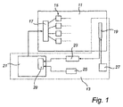
図1には、発光ユニット11および制御システム13が概略的に示されている。発光ユニット11は、LEDのアレイ15と、LED15を活性化させる電源ユニット17とを有する。LED15は、異なる色;主として、青色、緑色および赤色の光を放射する。当業者には明らかなように、通常の場合、制御システム13、電源ユニット17およびLED15は、全てPCB(プリント回路基盤)上に配置される。なお、図1には、いくつかの実施例に使用される部品のみが示されている。
FIG. 1 schematically shows the
制御システムは、検出ユニット19を有し、この検出ユニットは、発光ユニット11から放射される光の検出に使用され、制御ユニット21は、検出光に基づいて、発光ユニット11の光出力を制御する。特に、制御システムは、抑制ユニット23を有し、このユニットは、検出ユニット19の出力側に接続され、検出ユニット19からの光出力信号が受信される入力側と、制御ユニット21に接続され、制御ユニット21に改良された光出力信号を供給する出力側を有する。さらに制御ユニット13は、制御ユニット21に接続される照合信号発生ユニット25と、検出ユニット19に接続される検出パルス発生器27とを有する。制御ユニット21は、比較器29を有する。
The control system has a
制御システムは、以下のように作動する。時間は、前述のようにフレームに分割され、フレームの長さ、すなわち期間は、図2aに示すように、フレーム時間またはフレーム期間Tfと呼ばれる。各フレームのフレーム時間内で、異なる色の光を放射するLEDは、異なる広い時間窓の間に発光する。図2aを参照すると、例えば、次のように仮定される:赤色光を放射する全てのLED15は、時間窓31の間に発光され、その幅すなわち期間は、w1である;緑色のLED15は、時間窓33の間に発光し、その幅はw2であり、この幅はw1よりも広く、青色のLED15は、時間窓35内で発光し、この幅w3は、w2よりも広い。3つの時間窓31、33、35の各々の開始端は、それらの窓が重なるフレームの開始端では同時に生じる。従って、以降第1の期間とも呼ばれる赤色光の窓31内では、発光ユニット11の出力光に、緑および青の光も存在する。赤色光の窓31の終端と緑色光の窓33の終端の間の、第2の期間内では、緑色光および青色光が存在する。緑色光の窓の終端と青色光の窓の終端の間の、第3の時間内では、青色光のみが存在する。最後に、青色光の窓の終端と次のフレームの開始端の間の、第4の期間内では、いずれのLED15も発光しない。
The control system operates as follows. The time is divided into frames as described above, and the length of the frame, ie the period, is called the frame time or the frame period T f as shown in FIG. 2a. Within the frame time of each frame, LEDs that emit light of different colors emit during different wide time windows. Referring to FIG. 2a, for example, it is assumed that: All
この実施例では、検出パルス発生器27は、第1から第4の期間の各々の間に、各一つのパルスを発生し、すなわち、単位フレーム毎に、合計4つのパルスが発生する。パルスは、検出器ユニット19の作動を制御し、各パルスの期間、検出器ユニット19は、発光ユニット11の光出力を検出すなわち測定する。いかなる周囲の干渉光もLED光には混合されず、従って、干渉光は検出されない。仮に存在する場合でも、第4のパルス期間の間は、周囲干渉光、例えば一定のバックグラウンド光のみが検出される。各フレームにおいて、パルスは、前のフレームに対応する期間内で移動する。いかなる適当な方法が適用されても良いが、この移動は、準無秩序に定められることが好ましい。当業者は、この方法を決定することができる。各検出の実施に対して、検出ユニット10は、光出力信号を発生し、この信号は、抑制ユニット23に供給される。抑制ユニット23は、当業者には公知のいくつかの抑制アルゴリズムを用いて、光出力信号の干渉光信号部分を抑制する。抑制ユニットは、平均化ユニットを有し、平均化操作が行われる。例えば、標準的な平均化法が使用され、この方法では、光出力信号の予め定められた数、例えば10回分の測定が加えられ、その後、その回数で除算が行われる。別の方法は、浮動平均化処理である。この場合も、予め定められた数の値で平均化が行われる。新たな値を加えた場合、リスト中で最古のものが削除され、再度平均化が行われる。この方法では、各フレームの設定を調整することができる。さらに別の可能な方法は、重量平均処理である。周期的な干渉周囲光の寄与を遮断するため、平均化以外の方法を使用することも可能であることに留意する必要がある。その一例は、フーリエ解析であり、例えば周波数解析である。
In this embodiment, the detection pulse generator 27 generates one pulse during each of the first to fourth periods, that is, a total of four pulses are generated per unit frame. The pulses control the operation of the
この方法では、検出パルスは、非周期的に生じるため、少なくとも周期的なパルス状の周囲光、および一定の周囲バックグラウンド光を抑制することができる。パルス移動の形の非周期的な検出のため、前記第1から第4の周期と同じ期間に、周期的に生じる外部光信号パルスは、各事象で検出されず、これにより、光出力信号の全信号レベルに対する相対的な影響が抑制される。従って、抑制ユニット23は、改善された光出力信号を出力し、この信号が制御ユニット21に供給される。
In this method, since the detection pulse is generated aperiodically, at least periodic pulsed ambient light and constant ambient background light can be suppressed. Due to the non-periodic detection in the form of pulse movement, the external optical signal pulses that occur periodically in the same period as the first to fourth periods are not detected at each event, so that the optical output signal The relative influence on the total signal level is suppressed. Therefore, the
制御ユニット21は、比較器29を用いて、改良された光出力信号と照合信号とを、色度、すなわち信号の色バランスおよび光強度について比較する。差異がある場合、制御ユニット21は、適切な調節信号を発生し、この信号が電源ユニット17の方に供給される、平均化により、この調節は、各フレーム毎ではなく、より長い頻度、例えば10フレーム毎に行われ、この周期は、どのような平均化法が使用されたか、および発光ユニットの適用例によって変化する。通常の場合、電源ユニット17は、LED15用のPWM(パルス幅変調)電圧信号を発生する。当然のことながら、活性化信号の他の種類の変調も可能であり、これは当業者には明らかである。そのいくつかの例は、周波数変調、振幅変調、ビット角度またはデジタル変調、位相角度変調、およびビット電圧変調である。例えば、周波数変調の場合、フレーム時間Tfが変化することに留意する必要がある。次に、検出パルス発生器27は、変化に対応するように調整される。全ての場合において、フレーム時間は、50Hzの周波数に対応して、人間の目の典型的な遅延時間である約20msよりも短くなる。LED当たりのパルス幅は、その色の所望の光の強度によって定められ、すなわちこれは、必要な色度および発光ユニット11の調光性能に依存する。
The
調節信号は、電圧パルスの調整を促し、異なる色のLED光の強度に関して、LED15の光出力に変化が生じる。PWMの場合、図2aに示すように、強度の調節は、時間窓w1乃至w3の幅を変えることにより行われる。
The adjustment signal prompts the adjustment of the voltage pulse and causes a change in the light output of the
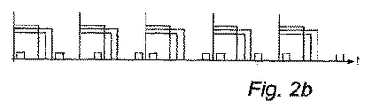
別の実施例のタイミング図を図2bに示す。ここでは、各フレームにおいて、2つの検出パルスのみが発生する。第1のパルスは、w1の間、すなわち発光ユニットの出力光に、全ての色が存在するときに生じる。第2のパルスは、全てのLED15がオフ状態となっているときに生じる。前述の実施例のように、パルスは、異なるフレームにおいて、フレームの開始端に対して、異なる時間で生じる。
A timing diagram for another embodiment is shown in FIG. 2b. Here, only two detection pulses are generated in each frame. The first pulse occurs during w1, ie when all colors are present in the output light of the light emitting unit. The second pulse occurs when all
図2cには、前述の実施例を修正した、さらに別のタイミング図が示されている。ここでは、LED15の光出力の測定用の検出パルスは、フレーム内でしばしば繰り返され、しばしば省略される。従って、あるフレームには、2つのそのようなパルスが存在し、いくつかのフレームには、そのようなパルスは含まれない。
FIG. 2c shows a further timing diagram, modified from the previous embodiment. Here, the detection pulse for measuring the light output of the
図2dには、さらに別の実施例のタイミング図が示されている。ここでは、LED放射窓w1乃至w3のシフトまたは対称化により、非周期的な特性が得られている。従って、図の第1のフレームから第2のフレームにおいて、時間窓w1乃至w3は、右側にシフトし、遅延化する。このため、例えば、第1の検出パルスは、フルカラー時間ではなく、ブラック期間に生じる。光出力信号を処理する計算が実施された場合、制御ユニットは、これらのシフトした検出特性を把握する。第4のフレームから第5のフレームでは、フレームの境界間で、時間窓が対称化される。これらの時間窓操作の結果は、前述のような、異なる時間で検出パルスが生じる場合と同様である。 FIG. 2d shows a timing diagram of yet another embodiment. Here, non-periodic characteristics are obtained by shifting or symmetrizing the LED emission windows w1 to w3. Accordingly, in the first frame to the second frame in the figure, the time windows w1 to w3 are shifted to the right and delayed. For this reason, for example, the first detection pulse occurs not in the full color time but in the black period. If a calculation is performed to process the optical output signal, the control unit keeps track of these shifted detection characteristics. In the fourth to fifth frames, the time windows are symmetrized between the frame boundaries. The results of these time window operations are the same as when detection pulses occur at different times as described above.
図2eには、さらに別の実施例のタイミング図が示されている。ここでは、LED放射窓は、より無秩序にシフトしているが、得られる結果は、前述の実施例と同様である。 FIG. 2e shows a timing diagram of yet another embodiment. Here, the LED emission window is shifted more disorderly, but the obtained result is the same as that of the above-mentioned embodiment.
図2fには、さらに別のタイミング図が示されている。ここでは、検出パルスの幅pw1乃至pw4が、フレーム毎に変化する。対応する光出力信号は、この幅、すなわち時間によって分割される。必要に応じて平均化処理と組み合わされた、この検出パルス幅の変調によって、周期的な周囲光の妨害の影響が排除/軽減される。検出パルスの開始時間および/または終了時間は、変化するため、この実施例も、非周期的な検出を行う方法として定義することができる。 In FIG. 2f, yet another timing diagram is shown. Here, the widths pw 1 to pw 4 of the detection pulse change for each frame. The corresponding light output signal is divided by this width, ie time. This detection pulse width modulation, combined with an averaging process as necessary, eliminates / reduces the effects of periodic ambient light interference. Since the start time and / or end time of the detection pulse changes, this embodiment can also be defined as a method of performing aperiodic detection.
図2gには、さらに別の実施例のタイミング図が示されている。ここでは、LEDは、連続的にオンにされ、ある期間の間、これらの全てのLEDが同時に発光する。図2aに示すような、放射窓内で検出パルスを時間的にシフトさせる方法が適用される。 FIG. 2g shows a timing diagram of yet another embodiment. Here, the LEDs are turned on continuously and all these LEDs emit light simultaneously for a period of time. A method of shifting the detection pulse in time within the radiation window as shown in FIG. 2a is applied.
以上、本発明による発光ユニットの実施例について説明した。これらは、単なる一例であって、本発明を限定するものと解してはならない。本発明の範囲内で、多くの変更および更なる別の実施例が可能であることは、当業者には明らかである。 The embodiment of the light emitting unit according to the present invention has been described above. These are merely examples and should not be construed as limiting the invention. It will be apparent to those skilled in the art that many modifications and further alternative embodiments are possible within the scope of the invention.
図2cおよび2fに示す原理は、図1に示すような4つのパルスに適用しても良い。ここでは、明確化のため、パルスが2つの場合について示されている。 The principles shown in FIGS. 2c and 2f may be applied to four pulses as shown in FIG. Here, for clarity, two pulses are shown.
LED発光の時間窓は、重ならないように調整しても良く、この場合、各検出パルスの間に、単一の色のLED光が放射される。 The LED emission time windows may be adjusted so that they do not overlap, in which case a single color of LED light is emitted between each detection pulse.
検出器は、概略的に発光ユニットの出口端に設置される。当然のことながら、実際には、検出器は、PCB上のLEDと並べたり、発光ユニットの壁に並べたりして、多くの場所に配置することができる。また、配置およびその他の因子に応じて、検出器には、LEDからの直接光、または反射光のいずれを照射しても良い。国際公開第WO02/099333号パンフレットには、LED内に検出器が配置された例が示されている。検出器に光出力の一部を反射する反射器を、発光ユニットの光出力側に配置しても良い。 The detector is generally installed at the outlet end of the light emitting unit. Of course, in practice the detectors can be placed in many places, either side by side with the LEDs on the PCB or side by side on the wall of the light emitting unit. Further, depending on the arrangement and other factors, the detector may be irradiated with either direct light from the LED or reflected light. International Publication No. WO02 / 099333 pamphlet shows an example in which a detector is arranged in an LED. A reflector that reflects part of the light output to the detector may be arranged on the light output side of the light emitting unit.
非周期的な特性を得る前述の代替例の多くを、必要に応じて組み合わせても良い。 Many of the aforementioned alternatives that obtain aperiodic characteristics may be combined as needed.
この場合、前述の実施例に示すように、光出力のフィードバック処理に、非周期性が導入される。処理の観点から、光出力の検出は、非周期的に実施され、例えば、検出器に対して非周期的に検出パルスを発生させることにより、あるいは非周期的にLED発光を生じさせることにより、またはこれらの両方により実施される。この場合、従来の抑制アルゴリズムによって、特にパルス光のような周囲光の干渉を除去し、または軽減することが可能になる。 In this case, as shown in the above-described embodiment, non-periodicity is introduced into the feedback process of the optical output. From a processing point of view, the detection of the light output is performed aperiodically, for example, by generating a detection pulse aperiodically for the detector, or by aperiodically generating LED emission. Or both. In this case, it is possible to eliminate or reduce interference of ambient light, particularly pulsed light, with conventional suppression algorithms.
本願の目的のため、特に従属請求項に関して、「有する」という用語は、他の要素またはステップを排斥するものではなく、「一つの」という用語は、複数のものを排斥するものではないことは、当業者には明らかであることに留意する必要がある。また、当業者には明らかなように、前述の少なくとも一部は、ハードウェアおよびソフトウェアで実現しても良い。 For the purposes of this application, particularly with respect to the dependent claims, the term “comprising” does not exclude other elements or steps, and the term “a” does not exclude a plurality. It should be noted that this will be apparent to those skilled in the art. Further, as will be apparent to those skilled in the art, at least a part of the above may be realized by hardware and software.
Claims (18)
当該制御システムは、前記発光ユニットの前記光出力を検出して、光出力信号を提供する検出ユニットと、該検出ユニットに検出パルスを提供する検出パルス発生器と、前記光出力信号における周囲光の干渉を抑制して、改良された光出力信号を提供する抑制ユニットと、前記発光ユニットの所望の光出力を表す照合信号と前記改良された光出力信号の比較に基づいて、前記発光ユニットの前記光出力信号を制御する制御ユニットとを有し、
前記検出パルス発生器は、非周期的に検出パルスを発生することを特徴とする制御システム。 A control system for controlling the light output of a light emitting unit having at least one LED that emits light of at least one color,
The control system detects the light output of the light emitting unit and provides a light output signal, a detection pulse generator for providing a detection pulse to the detection unit, and ambient light in the light output signal. A suppression unit that suppresses interference and provides an improved light output signal; and a comparison of the improved light output signal with a verification signal that represents a desired light output of the light emitting unit and the light output unit A control unit for controlling the optical output signal,
The control system, wherein the detection pulse generator generates detection pulses aperiodically.
前記検出パルスは、異なるフレームにおいて、前記フレームの開始端に対して、異なる時間で開始されることを特徴とする請求項1に記載の制御システム。 Time is divided into frames
2. The control system according to claim 1, wherein the detection pulse is started at different times with respect to a start end of the frame in different frames.
前記検出パルス発生器は、フレームのいくつかの時間間隔では、そのような組み合わせの検出パルスを繰り返し、同じフレームのある別の時間間隔では、検出パルスが排除されるように配置されることを特徴とする請求項2に記載の制御システム。 In order to detect a predetermined combination of LED light colors, each detection pulse occurs, the combination being present within the time interval of each frame,
The detection pulse generator is arranged to repeat such a combination of detection pulses at some time intervals of the frame and to eliminate the detection pulses at some other time interval of the same frame. The control system according to claim 2.
前記検出パルス発生器は、いくつかのフレーム内では、そのような組み合わせの検出パルスを繰り返し、他のフレーム内では、検出パルスが排除されるように配置されることを特徴とする請求項2に記載の制御システム。 In order to detect a predetermined combination of LED light colors, each detection pulse occurs, said combination being present within the time interval of each frame,
3. The detection pulse generator according to claim 2, wherein the detection pulse generator is arranged to repeat such a combination of detection pulses in some frames and to eliminate detection pulses in other frames. The described control system.
前記活性化は、非周期的であることを特徴とする前記請求項のいずれか一つに記載の制御システム。 Furthermore, the control unit is arranged to control the activation of the LED,
The control system according to claim 1, wherein the activation is aperiodic.
前記活性化は、一つのフレームから別のフレームの開始端に対する前記時間窓のシフト化、および一つのフレームと別のフレームの間の境界での前記時間窓の対称化、のいずれか一つにより実施されることを特徴とする請求項5に記載の制御システム。 Time is divided into frames, and the LEDs are activated to emit light within individual time windows within the frame,
The activation is by any one of shifting the time window from one frame to the start of another frame and symmetrizing the time window at the boundary between one frame and another. 6. The control system according to claim 5, wherein the control system is implemented.
前記請求項のいずれか一つに記載の制御システムを有することを特徴とする発光ユニット。 A light emitting unit comprising at least one LED emitting at least one color of light,
A light-emitting unit comprising the control system according to claim 1.
前記発光ユニットの光出力を非周期的に検出して、これにより光出力信号を発生するステップと、
前記光出力信号における周囲の干渉を抑制して、これにより、改良された光出力信号を発生するステップと、
前記改良された光出力信号と、前記発光ユニットの所望の光出力を表す照合信号とを比較するステップと、
前期比較に基づいて、前記発光ユニットの前記光出力を制御するステップと、
を有することを特徴とする方法。 A method for controlling a light emitting unit having at least one LED that emits light of at least one color comprising:
Detecting the light output of the light emitting unit aperiodically, thereby generating a light output signal;
Suppressing ambient interference in the light output signal, thereby generating an improved light output signal;
Comparing the improved light output signal with a verification signal representing a desired light output of the light emitting unit;
Controlling the light output of the light emitting unit based on a previous comparison;
A method characterized by comprising:
前記非周期的に検出するステップは、異なるフレームにおいて、前記フレームの開始端に対して、異なる時間で検出パルスを発生するステップを有することを特徴とする請求項11に記載の方法。 Time is divided into frames
12. The method according to claim 11, wherein the aperiodic detection includes generating detection pulses at different times with respect to a start edge of the frame in different frames.
前記非周期的に検出するステップは、それらのいくつかの時間間隔内で、そのような組み合わせの検出パルスを発生するステップと、それらのいくつかの時間間隔の別の組み合わせのパルスの発生を排除するステップとを有することを特徴とする請求項12に記載の方法。 In order to detect a predetermined combination of LED light colors, each detection pulse occurs, said combination being present within the time interval of each frame,
The aperiodic detection step eliminates the generation of such a combination of detection pulses within those several time intervals and the generation of another combination of those several time intervals. 13. The method of claim 12, further comprising the step of:
前記非周期的に検出するステップは、前記フレームの長さを変化させるステップを有することを特徴とする請求項11、12または13に記載の方法。 Time is divided into frames
14. The method according to claim 11, 12 or 13, wherein the aperiodic detection comprises changing the length of the frame.
前記LEDは、前記フレーム内の個々の時間窓内で発光するように活性化され、
前記非周期的に活性化させるステップは、一つのフレームから別のフレームの開始端に対し前記時間窓をシフトするステップ、および一つのフレームと別のフレームの間の境界で前記時間窓を対称化するステップ、のいずれか一つを有することを特徴とする請求項11乃至15のいずれか一つに記載の方法。 Time is divided into frames
The LEDs are activated to emit light within individual time windows within the frame,
The step of aperiodically activating comprises shifting the time window from one frame to the start of another frame, and symmetrizing the time window at the boundary between one frame and another frame 16. The method according to any one of claims 11 to 15, comprising any one of the following steps:
Applications Claiming Priority (2)
| Application Number | Priority Date | Filing Date | Title |
|---|---|---|---|
| EP04105921 | 2004-11-19 | ||
| PCT/IB2005/053745 WO2006054230A1 (en) | 2004-11-19 | 2005-11-14 | A feedback control system for controlling the light output of a led unit |
Publications (1)
| Publication Number | Publication Date |
|---|---|
| JP2008521237A true JP2008521237A (en) | 2008-06-19 |
Family
ID=35517519
Family Applications (1)
| Application Number | Title | Priority Date | Filing Date |
|---|---|---|---|
| JP2007542398A Ceased JP2008521237A (en) | 2004-11-19 | 2005-11-14 | Feedback control system for controlling light output of LED unit |
Country Status (9)
| Country | Link |
|---|---|
| US (1) | US7786678B2 (en) |
| EP (1) | EP1815719B1 (en) |
| JP (1) | JP2008521237A (en) |
| KR (1) | KR20070086371A (en) |
| CN (1) | CN100488329C (en) |
| AT (1) | ATE463145T1 (en) |
| DE (1) | DE602005020347D1 (en) |
| TW (1) | TW200625246A (en) |
| WO (1) | WO2006054230A1 (en) |
Cited By (2)
| Publication number | Priority date | Publication date | Assignee | Title |
|---|---|---|---|---|
| JP2008197048A (en) * | 2007-02-15 | 2008-08-28 | Honda Motor Co Ltd | Environment recognition device |
| KR20180068946A (en) * | 2018-06-15 | 2018-06-22 | 엘지디스플레이 주식회사 | Driving circuit of light emitting diodes and method driving of thereof |
Families Citing this family (18)
| Publication number | Priority date | Publication date | Assignee | Title |
|---|---|---|---|---|
| BRPI0621997A2 (en) * | 2006-09-21 | 2011-12-27 | Thomson Licensing | Method and system for three-dimensional model acquisition |
| WO2008083695A1 (en) * | 2006-12-20 | 2008-07-17 | Patent-Treuhand-Gesellschaft für elektrische Glühlampen mbH | Device and method for measuring the intensity of the light of a first group of light sources of a lighting unit |
| DE102007034177B4 (en) | 2007-07-23 | 2009-06-10 | Diehl Aerospace Gmbh | Method for dimming the light emitted by LED lights, in particular in the passenger cabin of a commercial aircraft |
| EP2174531B1 (en) | 2007-07-23 | 2013-06-05 | Koninklijke Philips Electronics N.V. | Light emitting unit arrangement and control system and method thereof |
| CN101766056B (en) * | 2007-08-02 | 2013-05-22 | Nxp股份有限公司 | Electronic device having a plurality of light emitting devices |
| DE102007036978A1 (en) | 2007-08-06 | 2009-02-12 | Tridonicatco Gmbh & Co. Kg | Device and method for controlling the light output |
| EP2324684A1 (en) | 2008-09-04 | 2011-05-25 | Koninklijke Philips Electronics N.V. | Method and device for driving a multicolor light source |
| JP4868025B2 (en) * | 2009-05-25 | 2012-02-01 | サンケン電気株式会社 | Current balancing device and method, LED lighting apparatus, LCD backlight module, LCD display device |
| DE102009030733B4 (en) | 2009-06-26 | 2015-11-05 | Diehl Aerospace Gmbh | Method and device for color-variable illumination |
| US8390205B2 (en) | 2010-09-01 | 2013-03-05 | Osram Sylvania Inc. | LED control using modulation frequency detection techniques |
| US8384294B2 (en) | 2010-10-05 | 2013-02-26 | Electronic Theatre Controls, Inc. | System and method for color creation and matching |
| US8723450B2 (en) | 2011-01-12 | 2014-05-13 | Electronics Theatre Controls, Inc. | System and method for controlling the spectral content of an output of a light fixture |
| US8593074B2 (en) | 2011-01-12 | 2013-11-26 | Electronic Theater Controls, Inc. | Systems and methods for controlling an output of a light fixture |
| US8729815B2 (en) | 2012-03-12 | 2014-05-20 | Osram Sylvania Inc. | Current control system |
| US9060410B2 (en) | 2013-07-25 | 2015-06-16 | Terralux, Inc. | Active flicker cancellation in lighting systems |
| JP2016151893A (en) * | 2015-02-17 | 2016-08-22 | 株式会社東芝 | Image processing apparatus, article processing apparatus, and image processing method |
| GB2547428A (en) * | 2016-02-16 | 2017-08-23 | Feasa Entpr Ltd | Method and apparatus for testing optical outputs |
| US20190187721A1 (en) * | 2017-12-15 | 2019-06-20 | Ankobot (Shanghai) Smart Technologies Co., Ltd. | Control method and system, and mobile robot using the same |
Citations (3)
| Publication number | Priority date | Publication date | Assignee | Title |
|---|---|---|---|---|
| JP2004077585A (en) * | 2002-08-12 | 2004-03-11 | Alpine Electronics Inc | Method and device for controlling luminance of backlight |
| JP2004517445A (en) * | 2000-12-27 | 2004-06-10 | コーニンクレッカ フィリップス エレクトロニクス エヌ ヴィ | LED lighting device for adjusting color balance electrically |
| JP2004170721A (en) * | 2002-11-20 | 2004-06-17 | Nec Mitsubishi Denki Visual Systems Kk | Liquid crystal display device and method for setting common voltage of same device |
Family Cites Families (6)
| Publication number | Priority date | Publication date | Assignee | Title |
|---|---|---|---|---|
| US5471052A (en) * | 1993-10-25 | 1995-11-28 | Eaton Corporation | Color sensor system using a secondary light receiver |
| FI109632B (en) * | 2000-11-06 | 2002-09-13 | Nokia Corp | White lighting |
| US6507159B2 (en) | 2001-03-29 | 2003-01-14 | Koninklijke Philips Electronics N.V. | Controlling method and system for RGB based LED luminary |
| US6741351B2 (en) | 2001-06-07 | 2004-05-25 | Koninklijke Philips Electronics N.V. | LED luminaire with light sensor configurations for optical feedback |
| US6630801B2 (en) * | 2001-10-22 | 2003-10-07 | Lümileds USA | Method and apparatus for sensing the color point of an RGB LED white luminary using photodiodes |
| US7148632B2 (en) * | 2003-01-15 | 2006-12-12 | Luminator Holding, L.P. | LED lighting system |
-
2005
- 2005-11-14 AT AT05803067T patent/ATE463145T1/en not_active IP Right Cessation
- 2005-11-14 WO PCT/IB2005/053745 patent/WO2006054230A1/en not_active Ceased
- 2005-11-14 DE DE602005020347T patent/DE602005020347D1/en not_active Expired - Lifetime
- 2005-11-14 EP EP05803067A patent/EP1815719B1/en not_active Expired - Lifetime
- 2005-11-14 CN CNB2005800395857A patent/CN100488329C/en not_active Expired - Fee Related
- 2005-11-14 KR KR1020077013768A patent/KR20070086371A/en not_active Abandoned
- 2005-11-14 US US11/719,299 patent/US7786678B2/en not_active Expired - Fee Related
- 2005-11-14 JP JP2007542398A patent/JP2008521237A/en not_active Ceased
- 2005-11-16 TW TW094140268A patent/TW200625246A/en unknown
Patent Citations (3)
| Publication number | Priority date | Publication date | Assignee | Title |
|---|---|---|---|---|
| JP2004517445A (en) * | 2000-12-27 | 2004-06-10 | コーニンクレッカ フィリップス エレクトロニクス エヌ ヴィ | LED lighting device for adjusting color balance electrically |
| JP2004077585A (en) * | 2002-08-12 | 2004-03-11 | Alpine Electronics Inc | Method and device for controlling luminance of backlight |
| JP2004170721A (en) * | 2002-11-20 | 2004-06-17 | Nec Mitsubishi Denki Visual Systems Kk | Liquid crystal display device and method for setting common voltage of same device |
Cited By (3)
| Publication number | Priority date | Publication date | Assignee | Title |
|---|---|---|---|---|
| JP2008197048A (en) * | 2007-02-15 | 2008-08-28 | Honda Motor Co Ltd | Environment recognition device |
| KR20180068946A (en) * | 2018-06-15 | 2018-06-22 | 엘지디스플레이 주식회사 | Driving circuit of light emitting diodes and method driving of thereof |
| KR101973501B1 (en) * | 2018-06-15 | 2019-04-29 | 엘지디스플레이 주식회사 | Driving circuit of light emitting diodes and method driving of thereof |
Also Published As
| Publication number | Publication date |
|---|---|
| US7786678B2 (en) | 2010-08-31 |
| EP1815719A1 (en) | 2007-08-08 |
| CN100488329C (en) | 2009-05-13 |
| EP1815719B1 (en) | 2010-03-31 |
| US20090140659A1 (en) | 2009-06-04 |
| TW200625246A (en) | 2006-07-16 |
| ATE463145T1 (en) | 2010-04-15 |
| KR20070086371A (en) | 2007-08-27 |
| CN101061753A (en) | 2007-10-24 |
| DE602005020347D1 (en) | 2010-05-12 |
| WO2006054230A1 (en) | 2006-05-26 |
Similar Documents
| Publication | Publication Date | Title |
|---|---|---|
| JP2008521237A (en) | Feedback control system for controlling light output of LED unit | |
| JP5409622B2 (en) | Light emitting unit configuration and control system and method | |
| US8664864B2 (en) | Method and apparatus for controlling and measuring aspects of time-varying combined light | |
| KR101193908B1 (en) | Method and apparatus for controlling an led based light system | |
| US8390205B2 (en) | LED control using modulation frequency detection techniques | |
| TWI498049B (en) | Three-color rgb led color mixing and control by variable frequency modulation | |
| US8358075B2 (en) | Device and a method for controlling light emission | |
| US20110057571A1 (en) | Device and method for controlling the color point of an led light source | |
| US20130181612A1 (en) | Light emitting apparatus and method for controlling the same | |
| KR20110098707A (en) | LED brightness control by WMF | |
| JP2011044367A5 (en) | ||
| WO2009040705A2 (en) | Method and apparatus for light intensity control with drive current modulation | |
| US7920111B2 (en) | LED-based optical system and method of compensating for aging thereof | |
| JP2005340809A (en) | Light emitting device, light emitting system, and control method thereof | |
| KR102824649B1 (en) | Light source device and light emission control | |
| JP2007080540A (en) | Lighting system | |
| JP2011166155A (en) | Method for operating light-emitting diode device, and circuit device | |
| WO2010049882A2 (en) | Lighting unit with temperature protection | |
| US11805585B2 (en) | Light emitting diode, LED, based lighting device arranged for emitting a particular color of light, as well as a corresponding method | |
| JP5558690B2 (en) | Lighting system | |
| US20060232501A1 (en) | Method and apparatus for implementing a pulse skip method of controlling light intensity | |
| WO2022209917A1 (en) | Light source device | |
| JP2009081353A5 (en) |
Legal Events
| Date | Code | Title | Description |
|---|---|---|---|
| A621 | Written request for application examination |
Free format text: JAPANESE INTERMEDIATE CODE: A621 Effective date: 20081113 |
|
| A977 | Report on retrieval |
Free format text: JAPANESE INTERMEDIATE CODE: A971007 Effective date: 20110713 |
|
| A131 | Notification of reasons for refusal |
Free format text: JAPANESE INTERMEDIATE CODE: A131 Effective date: 20110719 |
|
| A601 | Written request for extension of time |
Free format text: JAPANESE INTERMEDIATE CODE: A601 Effective date: 20111017 |
|
| A602 | Written permission of extension of time |
Free format text: JAPANESE INTERMEDIATE CODE: A602 Effective date: 20111024 |
|
| A521 | Request for written amendment filed |
Free format text: JAPANESE INTERMEDIATE CODE: A523 Effective date: 20120119 |
|
| A01 | Written decision to grant a patent or to grant a registration (utility model) |
Free format text: JAPANESE INTERMEDIATE CODE: A01 Effective date: 20121127 |
|
| A045 | Written measure of dismissal of application [lapsed due to lack of payment] |
Free format text: JAPANESE INTERMEDIATE CODE: A045 Effective date: 20130326 |