JP2008528131A - Video-assisted laryngeal mask airway device - Google Patents
Video-assisted laryngeal mask airway device Download PDFInfo
- Publication number
- JP2008528131A JP2008528131A JP2007552404A JP2007552404A JP2008528131A JP 2008528131 A JP2008528131 A JP 2008528131A JP 2007552404 A JP2007552404 A JP 2007552404A JP 2007552404 A JP2007552404 A JP 2007552404A JP 2008528131 A JP2008528131 A JP 2008528131A
- Authority
- JP
- Japan
- Prior art keywords
- laryngeal mask
- video sensor
- airway device
- laryngeal
- digital video
- Prior art date
- Legal status (The legal status is an assumption and is not a legal conclusion. Google has not performed a legal analysis and makes no representation as to the accuracy of the status listed.)
- Pending
Links
- 238000012545 processing Methods 0.000 claims abstract description 22
- 239000006260 foam Substances 0.000 claims description 17
- 238000005286 illumination Methods 0.000 claims description 16
- 230000029058 respiratory gaseous exchange Effects 0.000 claims description 10
- 238000007789 sealing Methods 0.000 claims description 4
- 230000008859 change Effects 0.000 claims description 3
- 230000002685 pulmonary effect Effects 0.000 claims description 3
- 230000000007 visual effect Effects 0.000 claims description 3
- 238000004891 communication Methods 0.000 claims description 2
- 238000012790 confirmation Methods 0.000 claims description 2
- 238000003384 imaging method Methods 0.000 abstract description 3
- 238000012897 Levenberg–Marquardt algorithm Methods 0.000 description 69
- 238000002627 tracheal intubation Methods 0.000 description 21
- 210000003800 pharynx Anatomy 0.000 description 9
- 239000013307 optical fiber Substances 0.000 description 8
- 238000003780 insertion Methods 0.000 description 7
- 230000037431 insertion Effects 0.000 description 7
- 210000000867 larynx Anatomy 0.000 description 7
- 210000004072 lung Anatomy 0.000 description 7
- 210000003437 trachea Anatomy 0.000 description 7
- 238000012800 visualization Methods 0.000 description 7
- 206010002091 Anaesthesia Diseases 0.000 description 6
- 230000037005 anaesthesia Effects 0.000 description 6
- 238000000034 method Methods 0.000 description 6
- 239000000835 fiber Substances 0.000 description 5
- 210000004704 glottis Anatomy 0.000 description 4
- 230000008901 benefit Effects 0.000 description 3
- 210000004556 brain Anatomy 0.000 description 3
- 238000011109 contamination Methods 0.000 description 3
- 210000002409 epiglottis Anatomy 0.000 description 3
- 210000003238 esophagus Anatomy 0.000 description 3
- 239000007789 gas Substances 0.000 description 3
- 210000003801 laryngeal nerve Anatomy 0.000 description 3
- 230000008569 process Effects 0.000 description 3
- 238000001356 surgical procedure Methods 0.000 description 3
- 206010003504 Aspiration Diseases 0.000 description 2
- 230000006931 brain damage Effects 0.000 description 2
- 231100000874 brain damage Toxicity 0.000 description 2
- 208000029028 brain injury Diseases 0.000 description 2
- 230000006378 damage Effects 0.000 description 2
- 239000013536 elastomeric material Substances 0.000 description 2
- 210000004211 gastric acid Anatomy 0.000 description 2
- 210000003736 gastrointestinal content Anatomy 0.000 description 2
- 239000007788 liquid Substances 0.000 description 2
- 238000012986 modification Methods 0.000 description 2
- 230000004048 modification Effects 0.000 description 2
- 230000003287 optical effect Effects 0.000 description 2
- 229920003023 plastic Polymers 0.000 description 2
- 239000004033 plastic Substances 0.000 description 2
- 238000010992 reflux Methods 0.000 description 2
- 210000002345 respiratory system Anatomy 0.000 description 2
- 239000007787 solid Substances 0.000 description 2
- 210000001685 thyroid gland Anatomy 0.000 description 2
- 238000009423 ventilation Methods 0.000 description 2
- 208000007204 Brain death Diseases 0.000 description 1
- 208000009612 Laryngismus Diseases 0.000 description 1
- 239000004698 Polyethylene Substances 0.000 description 1
- 208000003443 Unconsciousness Diseases 0.000 description 1
- 230000009471 action Effects 0.000 description 1
- 239000003994 anesthetic gas Substances 0.000 description 1
- 230000037007 arousal Effects 0.000 description 1
- QVGXLLKOCUKJST-UHFFFAOYSA-N atomic oxygen Chemical compound [O] QVGXLLKOCUKJST-UHFFFAOYSA-N 0.000 description 1
- 238000005452 bending Methods 0.000 description 1
- 230000000740 bleeding effect Effects 0.000 description 1
- 238000001444 catalytic combustion detection Methods 0.000 description 1
- 238000010276 construction Methods 0.000 description 1
- 238000013461 design Methods 0.000 description 1
- 238000003745 diagnosis Methods 0.000 description 1
- 238000005516 engineering process Methods 0.000 description 1
- 229920002457 flexible plastic Polymers 0.000 description 1
- 239000012530 fluid Substances 0.000 description 1
- 230000002496 gastric effect Effects 0.000 description 1
- 238000012966 insertion method Methods 0.000 description 1
- 238000002576 laryngoscopy Methods 0.000 description 1
- 238000002690 local anesthesia Methods 0.000 description 1
- 238000007726 management method Methods 0.000 description 1
- 238000004519 manufacturing process Methods 0.000 description 1
- 239000000463 material Substances 0.000 description 1
- 239000002184 metal Substances 0.000 description 1
- 238000012806 monitoring device Methods 0.000 description 1
- 238000012544 monitoring process Methods 0.000 description 1
- 210000003928 nasal cavity Anatomy 0.000 description 1
- 210000001989 nasopharynx Anatomy 0.000 description 1
- 239000001301 oxygen Substances 0.000 description 1
- 229910052760 oxygen Inorganic materials 0.000 description 1
- 230000000149 penetrating effect Effects 0.000 description 1
- 230000002093 peripheral effect Effects 0.000 description 1
- 239000006223 plastic coating Substances 0.000 description 1
- -1 polyethylene Polymers 0.000 description 1
- 229920000573 polyethylene Polymers 0.000 description 1
- 210000002416 recurrent laryngeal nerve Anatomy 0.000 description 1
- 230000028327 secretion Effects 0.000 description 1
- 239000004065 semiconductor Substances 0.000 description 1
- 230000000638 stimulation Effects 0.000 description 1
- 210000001260 vocal cord Anatomy 0.000 description 1
- 210000004916 vomit Anatomy 0.000 description 1
- 230000008673 vomiting Effects 0.000 description 1
Images



Classifications
-
- A—HUMAN NECESSITIES
- A61—MEDICAL OR VETERINARY SCIENCE; HYGIENE
- A61B—DIAGNOSIS; SURGERY; IDENTIFICATION
- A61B1/00—Instruments for performing medical examinations of the interior of cavities or tubes of the body by visual or photographical inspection, e.g. endoscopes; Illuminating arrangements therefor
- A61B1/267—Instruments for performing medical examinations of the interior of cavities or tubes of the body by visual or photographical inspection, e.g. endoscopes; Illuminating arrangements therefor for the respiratory tract, e.g. laryngoscopes, bronchoscopes
-
- A—HUMAN NECESSITIES
- A61—MEDICAL OR VETERINARY SCIENCE; HYGIENE
- A61M—DEVICES FOR INTRODUCING MEDIA INTO, OR ONTO, THE BODY; DEVICES FOR TRANSDUCING BODY MEDIA OR FOR TAKING MEDIA FROM THE BODY; DEVICES FOR PRODUCING OR ENDING SLEEP OR STUPOR
- A61M16/00—Devices for influencing the respiratory system of patients by gas treatment, e.g. ventilators; Tracheal tubes
- A61M16/04—Tracheal tubes
-
- A—HUMAN NECESSITIES
- A61—MEDICAL OR VETERINARY SCIENCE; HYGIENE
- A61M—DEVICES FOR INTRODUCING MEDIA INTO, OR ONTO, THE BODY; DEVICES FOR TRANSDUCING BODY MEDIA OR FOR TAKING MEDIA FROM THE BODY; DEVICES FOR PRODUCING OR ENDING SLEEP OR STUPOR
- A61M16/00—Devices for influencing the respiratory system of patients by gas treatment, e.g. ventilators; Tracheal tubes
- A61M16/04—Tracheal tubes
- A61M16/0402—Special features for tracheal tubes not otherwise provided for
- A61M16/0409—Special features for tracheal tubes not otherwise provided for with mean for closing the oesophagus
-
- A—HUMAN NECESSITIES
- A61—MEDICAL OR VETERINARY SCIENCE; HYGIENE
- A61M—DEVICES FOR INTRODUCING MEDIA INTO, OR ONTO, THE BODY; DEVICES FOR TRANSDUCING BODY MEDIA OR FOR TAKING MEDIA FROM THE BODY; DEVICES FOR PRODUCING OR ENDING SLEEP OR STUPOR
- A61M16/00—Devices for influencing the respiratory system of patients by gas treatment, e.g. ventilators; Tracheal tubes
- A61M16/04—Tracheal tubes
- A61M16/0434—Cuffs
- A61M16/0436—Special fillings therefor
-
- A—HUMAN NECESSITIES
- A61—MEDICAL OR VETERINARY SCIENCE; HYGIENE
- A61M—DEVICES FOR INTRODUCING MEDIA INTO, OR ONTO, THE BODY; DEVICES FOR TRANSDUCING BODY MEDIA OR FOR TAKING MEDIA FROM THE BODY; DEVICES FOR PRODUCING OR ENDING SLEEP OR STUPOR
- A61M16/00—Devices for influencing the respiratory system of patients by gas treatment, e.g. ventilators; Tracheal tubes
- A61M16/04—Tracheal tubes
- A61M16/0434—Cuffs
- A61M16/0445—Special cuff forms, e.g. undulated
-
- A—HUMAN NECESSITIES
- A61—MEDICAL OR VETERINARY SCIENCE; HYGIENE
- A61M—DEVICES FOR INTRODUCING MEDIA INTO, OR ONTO, THE BODY; DEVICES FOR TRANSDUCING BODY MEDIA OR FOR TAKING MEDIA FROM THE BODY; DEVICES FOR PRODUCING OR ENDING SLEEP OR STUPOR
- A61M16/00—Devices for influencing the respiratory system of patients by gas treatment, e.g. ventilators; Tracheal tubes
- A61M16/04—Tracheal tubes
- A61M16/0488—Mouthpieces; Means for guiding, securing or introducing the tubes
-
- A—HUMAN NECESSITIES
- A61—MEDICAL OR VETERINARY SCIENCE; HYGIENE
- A61B—DIAGNOSIS; SURGERY; IDENTIFICATION
- A61B1/00—Instruments for performing medical examinations of the interior of cavities or tubes of the body by visual or photographical inspection, e.g. endoscopes; Illuminating arrangements therefor
- A61B1/06—Instruments for performing medical examinations of the interior of cavities or tubes of the body by visual or photographical inspection, e.g. endoscopes; Illuminating arrangements therefor with illuminating arrangements
Landscapes
- Health & Medical Sciences (AREA)
- Pulmonology (AREA)
- Life Sciences & Earth Sciences (AREA)
- Veterinary Medicine (AREA)
- Biomedical Technology (AREA)
- Heart & Thoracic Surgery (AREA)
- Engineering & Computer Science (AREA)
- Animal Behavior & Ethology (AREA)
- General Health & Medical Sciences (AREA)
- Public Health (AREA)
- Hematology (AREA)
- Emergency Medicine (AREA)
- Anesthesiology (AREA)
- Surgery (AREA)
- Otolaryngology (AREA)
- Physiology (AREA)
- Biophysics (AREA)
- Nuclear Medicine, Radiotherapy & Molecular Imaging (AREA)
- Optics & Photonics (AREA)
- Pathology (AREA)
- Radiology & Medical Imaging (AREA)
- Physics & Mathematics (AREA)
- Medical Informatics (AREA)
- Molecular Biology (AREA)
- Endoscopes (AREA)
- Investigating, Analyzing Materials By Fluorescence Or Luminescence (AREA)
Abstract
喉頭マスク気道デバイスが提供され、該デバイスは、喉頭入口または他の気道構造の画像を提供するように配置された、CCD、CMOS、またはNMOSイメージングチップなどのビデオセンサを組み込む。該ビデオセンサは、再使用可能な処理ユニットに電気的に結合されており、該処理ユニットは、ビデオセンサによって生成された信号を受信し、患者の気道の内部のデジタル画像を生成する。その結果、臨床医は、デバイスを挿入する瞬間から、喉頭入口に対するマスクアパーチャの位置を即座に光学的に確認することができる。A laryngeal mask airway device is provided that incorporates a video sensor, such as a CCD, CMOS, or NMOS imaging chip, arranged to provide an image of the laryngeal entrance or other airway structure. The video sensor is electrically coupled to a reusable processing unit that receives a signal generated by the video sensor and generates a digital image inside the patient's airway. As a result, the clinician can immediately optically confirm the position of the mask aperture relative to the laryngeal entrance from the moment the device is inserted.
Description
本発明は、喉頭マスク気道および挿管喉頭マスクなどの、喉頭マスク気道デバイスに関し、該デバイスは、麻酔を投与するために使用され、デバイスのボウル内に搭載された一つ以上のビデオセンサを有することによって、デバイスの配置または気管内チューブの挿入を援助する。 The present invention relates to laryngeal mask airway devices, such as laryngeal mask airways and intubated laryngeal masks, which devices are used to administer anesthesia and have one or more video sensors mounted within the device bowl. To assist with device placement or endotracheal tube insertion.
喉頭マスク気道(「LMA」)は、気管内チューブの代わりに、または気管内チューブとともに、麻酔の投与において使用されることが公知である。LMAは、気管の中に気管内チューブを配置することなしに、患者の呼吸を可能にするが、逆流および誤嚥のリスクに対する保護をしない。市販で利用可能なLMAは、気管ではなく食道におけるチューブの不適切な配置のために気管内チューブによって経験されるリスクを低減するように設計されており、現在、すべての麻酔処置の1/3よりも多くにおいて使用されている。そのようなデバイスは、一般的に柔軟なチューブを含み、チューブは、膨張可能なカフによって取り囲まれたボウルを備えるマスク部分に結合されて連通している。デバイスは、咽頭の中に手探りで(blindly)挿入され得、そのように位置づけられると、マスク部分が声門のあたりを密封する。 The laryngeal mask airway (“LMA”) is known to be used in the administration of anesthesia instead of or in conjunction with the endotracheal tube. LMA allows the patient to breath without placing an endotracheal tube in the trachea, but does not protect against the risk of reflux and aspiration. Commercially available LMAs are designed to reduce the risk experienced by endotracheal tubes due to improper placement of the tube in the esophagus rather than the trachea, and currently one third of all anesthesia procedures Is used in more than. Such devices typically include a flexible tube that is coupled and in communication with a mask portion comprising a bowl surrounded by an inflatable cuff. The device can be blindly inserted into the pharynx, and when so positioned, the mask portion seals around the glottis.
LMAは一般的に成功しているにもかかわらず、緊急事態において、または胃の内容物を誤嚥するリスクがあり得るときなどに、気管の挿管は、通常は気道管理の主要な局面であり続けている。なぜなら、気管内にカフされたチューブが存在することは、嘔吐物内に存在する胃酸が肺に入って損傷することを防止するからである。しかし、気管の挿管は必ずしも可能ではなく、困難が経験されるときには、挿管する試みがなされている間に、胃酸によって肺が汚損されることが生じ得る。声門を目に見えるようにするために喉頭鏡を使用することが失敗した場合など、従来の手段による挿管の場合には、挿管を容易にする案内として、改変された形態のLMAが使用され得る。カリフォルニア州San DiegoのLMA North Americaによって流通させられているLMA−Fastrach(登録商標)は、そのようなデバイスであり、一般的に「挿管喉頭マスク」(「ILM」)と呼ばれている。 Although LMA is generally successful, tracheal intubation is usually a major aspect of airway management, such as in emergencies or when there may be a risk of aspiration of stomach contents continuing. This is because the presence of a cuffed tube in the trachea prevents gastric acid present in the vomit from entering and damaging the lungs. However, intubation of the trachea is not always possible, and when difficulties are experienced, the lungs can be contaminated by gastric acid while attempting to intubate. In the case of intubation by conventional means, such as when using a laryngoscope to make the glottis visible, a modified form of LMA can be used as a guide to facilitate intubation . LMA-Fastrach®, distributed by LMA North America, San Diego, California, is such a device and is commonly referred to as an “intubation laryngeal mask” (“ILM”).
ILMは、ILMチューブを通して気管内チューブを気管の中に通すことを高い程度で成功させるためには、気管内チューブが食道の中に通らないこと、または喉頭蓋に衝突して損傷させないことを確実にするために、ファイバースコープの支援が必要とされるという制約を有する。これらの危険性、特に前者は、検出されなければ死亡に至り得、喉頭鏡を使用した古典的な挿管において経験される危険性に類似している。ファイバースコープに支援された挿管は、ILMおよび気管内チューブの配置を目に見えるようにするためにファイバースコープが使用されるものであり、古典的な挿管が失敗したときに使用され得る。しかし、ファイバースコープに支援された挿管は、かなりの技能および時間を必要とするという不利があり、呼吸が達成され得なければ酸素不足による脳損傷または脳死が今にも起こりそうな場合には、大きな欠点である。 The ILM ensures that the endotracheal tube does not pass through the esophagus or impacts and damages the epiglottis in order to successfully pass the endotracheal tube through the ILM tube into the trachea. In order to do so, there is a restriction that the support of a fiberscope is required. These risks, especially the former, can lead to death if not detected and are similar to those experienced in classic intubation using a laryngoscope. Fiberscope-assisted intubation is where fiberscopes are used to make the ILM and endotracheal tube placement visible and can be used when classical intubation fails. However, fiberscope-assisted intubation has the disadvantage of requiring considerable skill and time and is a major drawback if brain damage or brain death due to lack of oxygen is likely to occur if breathing cannot be achieved. It is.
有利なことに、LMAおよびILM(集合的に「LMAデバイス」)は、挿管が不可能であることがわかった場合でさえも、患者を生存させ続けることを可能にする。なぜなら、喉頭鏡または光ファイバースコープ(「ファイバースコープ」)とは異なり、LMAデバイスのマスク部分は、声門のあたりに適切な密封を提供することによって、挿管の試みが行われている間に、穏やかな陽圧呼吸が維持されることを可能にする。このことは、従来技術と比較すると重要な利点である。なぜなら、死亡または脳損傷は、胃の内容物による肺の汚染よりも、肺を換気できないことによって、より頻繁に生じるからである。 Advantageously, LMA and ILM (collectively “LMA devices”) allow patients to continue to survive even if it is found that intubation is not possible. Because, unlike laryngoscopes or fiber optic scopes (“fiber scopes”), the mask portion of the LMA device provides gentle sealing during the intubation attempt by providing an appropriate seal around the glottis. Allows positive pressure breathing to be maintained. This is an important advantage compared to the prior art. This is because death or brain damage occurs more frequently due to inability to ventilate the lungs than contamination of the lungs with stomach contents.
光ファイバーに支援された挿管において、臨床医は、ファイバースコープを舌の後ろのあたりに(または鼻腔および鼻咽腔を通して)通過させ、次に喉頭が見えるようになるまでスコープの先端を下方に通過させることによって、喉頭アパーチャに到達する。このようにしてファイバースコープを挿入することは、時間および技能を要する。スコープは、一般的に、咽頭の断面積に対して小さな断面積を有するので、挿入の間にファイバースコープの先端が咽頭の一方の側や他方の側に遊走する可能性があり、したがって喉頭口の構造を見逃す。 In optical fiber assisted intubation, the clinician passes the fiberscope around the back of the tongue (or through the nasal cavity and nasopharynx) and then passes the scope tip down until the larynx is visible To reach the laryngeal aperture. Inserting a fiberscope in this way requires time and skill. Because the scope generally has a small cross-sectional area relative to the pharyngeal cross-sectional area, the tip of the fiberscope may migrate to one or the other side of the pharynx during insertion, and thus the laryngeal mouth Miss the structure.
さらに、ファイバースコープの先端は、咽頭に存在する分泌物による汚染、またはその通過によって引き起こされる出血から、保護されておらず、これらのいずれかまたは両方は、ファイバースコープ操作者の視界を不明瞭にし得る。さらに、ファイバースコープに支援される挿管によって経験されるさらなる問題は、視界が二次元であり、視野が非常に限定されていることである。これらのすべての要因の組み合わせが、光ファイバーに支援された挿管を、習得して維持することが困難な技能にしている。最後に、ファイバースコープは非常に高価であり、すべての病院がファイバースコープの費用を負担したり維持したりする経済力があるわけではなく、それによって臨床医がこの技術を使用するために必要な技能を有することを確実にすることがさらに困難になっている。 Furthermore, the tip of the fiberscope is not protected from contamination caused by secretions present in the pharynx or bleeding caused by its passage, either or both of which obscure the view of the fiberscope operator. obtain. Furthermore, a further problem experienced by fiberscope-assisted intubation is that the field of view is two-dimensional and the field of view is very limited. The combination of all these factors makes optical fiber assisted intubation a skill that is difficult to learn and maintain. Finally, fiberscopes are very expensive and not all hospitals have the economic power to bear and maintain the cost of fiberscopes, which is necessary for clinicians to use this technology. It is even more difficult to ensure that you have the skills.
上述の問題は、LMAデバイスがファイバースコープのための案内として使用される場合に、部分的に解決される。なぜなら、正しく挿入されれば、LMAデバイスのマスク部分は、マスクを取り巻くカフが展開されるときに下部咽頭のスペースを完全に満たすからである。デバイスは一回の動作で手探りで通過させられ得るので、最初の換気に対する時間は非常に速い。したがって、LMAデバイスを使用するときに、喉頭入口の視界は、LMAデバイスのチューブから下にファイバースコープを単に挿入することによって、非常に多くの場合において自動的に達成され、LMAデバイスはファイバースコープをその目標に向ける案内として作用する。そのような一つの方法は、Kinsingerらによる特許文献1に記載されている。 The above problems are partially solved when the LMA device is used as a guide for a fiberscope. This is because when correctly inserted, the mask portion of the LMA device completely fills the space in the lower pharynx when the cuff surrounding the mask is deployed. The time for the first ventilation is very fast because the device can be passed through in a single action. Thus, when using an LMA device, the view of the laryngeal entrance is automatically achieved in very many cases by simply inserting a fiberscope down from the tube of the LMA device, and the LMA device will Acts as a guide towards that goal. One such method is described in US Pat.
ひとたびLMAが患者の咽頭内に配置され、ファイバースコープがLMAのチューブ内に配置されると、慎重な態様で検査が実行される。なぜならLMAデバイスが展開されるとすぐに、適切な呼吸が確実にされるからである。市販で利用可能なILMを用いて、喉頭を見る可能性は一層高い。なぜなら、ILMチューブは硬くて、喉頭に対するマスクの直接的な操作を可能にする外部ハンドルが提供されており、それによって、臨床医は、手探りの挿入の間に完全な位置合わせが達成されない場合に、マスクの位置を変化させることができるからである。しかし、正確な位置合わせが達成されたかどうかを確かめるために、やはりファイバースコープがチューブに挿入されなければならない。 Once the LMA is placed in the patient's pharynx and the fiberscope is placed in the LMA's tube, the examination is performed in a careful manner. This is because as soon as the LMA device is deployed, proper breathing is ensured. The possibility of seeing the larynx with a commercially available ILM is even higher. Because the ILM tube is stiff and an external handle is provided that allows direct manipulation of the mask relative to the larynx so that the clinician can achieve perfect alignment during groping insertion This is because the position of the mask can be changed. However, a fiberscope must still be inserted into the tube to ascertain whether accurate alignment has been achieved.
Brainによる特許文献2は、取り外し可能な硬化する部材を受け入れる通路を有するLMAを記載しており、この部材はLMAをインストールするために使用され得る。この特許は、ひとたびLMAが配置されると、硬化する部材が通路から取り外されることを記載している。次に、光ファイバーが通路の中に挿入されることによって、喉頭入口を目に見えるようにして、気管内チューブ挿入を容易にする。Brainによる特許文献3もまた、光ファイバーを受け入れることによって気管内チューブの配置を容易にする通路を含むILMを記載している。 U.S. Pat. No. 6,057,017 to Brain describes an LMA having a passage for receiving a removable hardened member, which can be used to install the LMA. This patent describes that once the LMA is in place, the curing member is removed from the passage. An optical fiber is then inserted into the passageway to make the laryngeal inlet visible and facilitate endotracheal tube insertion. U.S. Pat. No. 6,057,017 to Brain also describes an ILM that includes a passageway that facilitates placement of the endotracheal tube by receiving an optical fiber.
最近の研究は、従来の手探りの挿入方法に対してLMAの配置を改善することにおいて、直接的な視覚化もまた有用であり得ることを示している。Campbellらによる非特許文献1は、喉頭鏡を使用して実行されるLMA配置(直接的な視覚化)を、手探りの配置と比較して、ファイバースコープの使用を記載している。この文献は、手探りの配置の場合の42%と比較して、喉頭鏡が使用された場合に90%を超えて理想的な配置が得られたことを観察している。 Recent studies have shown that direct visualization can also be useful in improving LMA placement over conventional grapple insertion methods. Non-Patent Document 1 by Campbell et al. Describes the use of a fiberscope, comparing LMA placement (direct visualization) performed using a laryngoscope with groping placement. This document observes that over 90% of the ideal placement was obtained when the laryngoscope was used compared to 42% for the grapple placement.
さらにまた、最近の研究は、LMAの気道チューブを通して配置されたファイバースコープを使用して喉頭神経を視覚化することによって、甲状腺手術の間に喉頭神経への損傷が大いに低減され得ることを示している。そのような2つの研究の結果は、M.C.ScheullerおよびD.Ellisonによる非特許文献2およびH.K.Eltzschigらによる非特許文献3に記載されている。
Furthermore, recent studies have shown that damage to the laryngeal nerve can be greatly reduced during thyroid surgery by visualizing the laryngeal nerve using a fiberscope placed through the LMA airway tube. Yes. The results of two such studies are C. Schüller and D.C. Non-Patent
上述に鑑みて、LMAおよび気管内チューブの配置を改善し、気道に関連する手術処置の間に患者の気道の視覚化を改善する、視覚化支援に対する認識されたニーズがある。Brainに対する上述の特許は、見ることを強化する光ファイバーコンポーネントを含むLMAデバイスを開示しているが、光ファイバーの使用にはいくつかの不利がある。一般的に、そのようなファイバーは、曲げる間に破損しやすく、高度の照明を必要とし、反射された光が光ファイバーを通過する際に画像が歪みやすい。さらに、光ファイバーを透過させられる画像を処理して表示するために必要なエレクトロニクスコンポーネントは高価であり、それによってそのようなデバイスの受け入れを限定している。 In view of the above, there is a recognized need for visualization assistance that improves the placement of the LMA and endotracheal tube and improves the visualization of the patient's airway during surgical procedures associated with the airway. Although the above-mentioned patent to Brain discloses LMA devices that include optical fiber components that enhance viewing, there are several disadvantages to the use of optical fibers. In general, such fibers are prone to breakage during bending, require a high degree of illumination, and the image is prone to distortion as the reflected light passes through the optical fiber. Furthermore, the electronics components required to process and display images that are transmitted through the optical fiber are expensive, thereby limiting the acceptance of such devices.
かねてより公知の光ファイバーシステムのこれらの欠点を認識して、一部のかねてより公知のデバイスは、改善された視覚化を提供するために、デバイスの遠位端に電荷結合デバイス(「CCD」)などのビデオカメラを組み込むことを試みてきた。Hillによる特許文献4は、遠位端に配置されたCCDカメラを有する気管内チューブを記載している。Smithらによる特許文献5およびBerallによる特許文献6は、それぞれ、遠位端の近くの搭載されたカメラを有し、該カメラがデバイスの画面上に表示される画像を生成する、喉頭鏡を開示している。しかし、これらのデバイスのすべては、上述の不利を被る。具体的には、これらのデバイスのいずれも、挿管プロセスが行われている間に、患者に適切な程度の呼吸を提供しない。 Recognizing these shortcomings of previously known fiber optic systems, some previously known devices have been charged coupled devices (“CCDs”) at the distal end of the device to provide improved visualization. Have tried to incorporate such video cameras. U.S. Pat. No. 6,053,831 to Hill describes an endotracheal tube with a CCD camera located at the distal end. U.S. Patent Nos. 5,099,059 and 6,566, 2006 to Smith, each discloses a laryngoscope having a mounted camera near the distal end that generates an image that is displayed on the screen of the device. is doing. However, all of these devices suffer from the disadvantages described above. Specifically, none of these devices provide the appropriate degree of breathing to the patient during the intubation process.
上述を鑑みて、LMAまたはILMのいずれかとして構成され、喉頭入口および他の気道構造の視覚化を提供する、デバイスのマスク部分またはチューブ部分に配置されたビデオセンサを含む、LMAデバイスを提供することが望ましくあり得る。 In view of the above, an LMA device is provided that includes a video sensor that is configured as either an LMA or an ILM and that provides a visualization of the laryngeal inlet and other airway structures and is disposed in the mask or tube portion of the device. It may be desirable.
CCD、CMOS、またはNMOSセンサなどの低コストの固体カメラ素子を組み込み、再使用可能な処理ユニットおよびディスプレイ画面に結合され得る、使い捨てのLMAデバイスを提供することも望ましくあり得る。 It may also be desirable to provide a disposable LMA device that incorporates a low cost solid state camera element such as a CCD, CMOS, or NMOS sensor and can be coupled to a reusable processing unit and display screen.
さらに、視野が交差する2つ以上のビデオセンサを有するLMAを提供することによって、臨床医が患者の気道の立体視を得ることを可能にすることが望ましくあり得る。 Furthermore, it may be desirable to allow a clinician to obtain a stereoscopic view of a patient's airway by providing an LMA having two or more video sensors that intersect the field of view.
さらにまた、膨張可能なカフが自己膨張するように配置されたLMAを提供することによって、臨床医がLMAデバイスを配置する間にカフを膨張させることを別々に留意する必要性を取り除くことが望ましくあり得る。
(本発明の概要)
上述のように、本発明の目的は、LMAデバイスを提供することであって、該デバイスは、LMAまたはILMのいずれかとして構成され、デバイスのチューブ、マスク、またはボウルの部分に配置されたビデオセンサを含むことによって、喉頭入口および他の気道構造の視覚化を提供する。
(Outline of the present invention)
As mentioned above, an object of the present invention is to provide an LMA device, which is configured as either an LMA or an ILM and is placed in a tube, mask or bowl portion of the device. Inclusion of the sensor provides visualization of the laryngeal inlet and other airway structures.
本発明の目的はまた、使い捨てのLMAデバイスを提供することであって、該デバイスは、CCD、CMOS、またはNMOSビデオセンサなどの低コストの固体カメラ素子と、発光ダイオード(「LED」)などの照明源とを組み込み、これらは再使用可能な処理ユニットおよびディスプレイ画面に結合され得る。 It is also an object of the present invention to provide a disposable LMA device that includes a low cost solid state camera element such as a CCD, CMOS, or NMOS video sensor and a light emitting diode (“LED”) or the like. Incorporating illumination sources, these can be coupled to reusable processing units and display screens.
本発明の別の目的は、視野が交差する2つ以上のビデオセンサを有するLMAデバイスを提供することであって、それによって臨床医が患者の気道の立体視を得ることを可能にする。 Another object of the present invention is to provide an LMA device having two or more video sensors whose fields of view intersect, thereby allowing the clinician to obtain a stereoscopic view of the patient's airway.
本発明のさらなる目的は、膨張可能なカフが自己膨張するように配置されたLMAデバイスを提供することであって、それによって、臨床医がLMAデバイスを配置する間にカフを膨張させることを別々に留意する必要性を取り除く。 It is a further object of the present invention to provide an LMA device that is arranged such that the inflatable cuff is self-inflating, thereby allowing the clinician to separately inflate the cuff during placement of the LMA device. Eliminate the need to keep in mind.
本発明のこれらのおよび他の目的は、LMAまたはILMとして構成され、CCD、CMOS、またはNMOSセンサなどの、喉頭入口および/または他の気道構造の画像を提供するように配置されたビデオセンサを組み込む、LMAデバイスを提供することによって達成される。このようにして、本発明のLMAデバイスは、臨床医が、デバイスの挿入の瞬間から、およびその後いつでも、喉頭入口に対するマスクアパーチャの位置を即座に光学的に確認することを可能にする。挿管喉頭マスクの場合には、ビデオセンサは、従来の気管内チューブを使用して、画像によって案内される挿管を可能にする。一つの好ましい実施形態において、LMAデバイスは、視野の交差する2つ以上のビデオセンサを含み得、それによって患者の気道の立体視を提供する。 These and other objects of the present invention include a video sensor configured as an LMA or ILM and arranged to provide images of the laryngeal inlet and / or other airway structures, such as CCD, CMOS, or NMOS sensors. This is accomplished by providing an LMA device that incorporates. In this way, the LMA device of the present invention allows the clinician to immediately optically confirm the position of the mask aperture relative to the laryngeal inlet from the moment of device insertion and anytime thereafter. In the case of an intubation laryngeal mask, the video sensor uses a conventional endotracheal tube to allow intubation guided by the image. In one preferred embodiment, the LMA device may include two or more video sensors that intersect the field of view, thereby providing a stereoscopic view of the patient's airway.
本発明の一つの局面によると、LMAデバイスは使い捨てであり、一回使用された後に廃棄される。LMAデバイスのビデオセンサは、リード線を含み、リード線はコネクタにおいて終結し、コネクタは再使用可能なユニットに結合され得、ユニットはビデオセンサからの信号を処理することによってデジタル画像を生成する。LMAデバイスはさらに、患者の気道の内部に照明を提供するために、LEDなどの照明システムを含み得る。好ましくは、LMAデバイスは、再使用可能なモジュールに結合され得る。該モジュールは、ビデオセンサに電力を供給するエレクトロニクスを収容し、ビデオセンサによって生成された信号を処理し、オプションとして照明システムに電力を供給する。再使用可能なモジュールはまた、ビデオシステムによって生成された画像を表示する画面を含み得、従来のディスプレイ上に表示するために適切な出力を入力し得る。 According to one aspect of the invention, the LMA device is disposable and discarded after a single use. The video sensor of the LMA device includes a lead that terminates at a connector, which can be coupled to a reusable unit that generates a digital image by processing the signal from the video sensor. The LMA device may further include an illumination system, such as an LED, to provide illumination within the patient's airway. Preferably, the LMA device can be coupled to a reusable module. The module contains electronics that supply power to the video sensor, processes signals generated by the video sensor, and optionally supplies power to the lighting system. The reusable module may also include a screen that displays images generated by the video system and may input appropriate output for display on a conventional display.
本発明の別の局面によると、LMAデバイスのマスク部分を取り囲むように配置されたカフは、液体不浸透性のプラスチックカフ内に配置された連続気泡発泡体を含む。連続気泡発泡体は、発泡体を機械的に圧縮して排気され得、次にカフを可逆的に密封することによって、圧縮された状態に保たれ得る。注入器を使用してカフの中に空気を注入することによってカフが膨張させられる従来のLMAデバイスとは対照的に、本発明のLMAデバイスのカフは、カフに接続された管腔を単に開封することによって展開され得る。このようにして、連続発泡気泡体は、自動的に膨張することによって、患者の声門のあたりを密封するように整合する。 According to another aspect of the invention, the cuff disposed to surround the mask portion of the LMA device includes an open cell foam disposed within a liquid-impermeable plastic cuff. The open cell foam can be evacuated by mechanically compressing the foam and then kept in a compressed state by reversibly sealing the cuff. In contrast to conventional LMA devices where the cuff is inflated by injecting air into the cuff using an injector, the cuff of the LMA device of the present invention simply opens the lumen connected to the cuff. Can be deployed. In this way, the open cell foam aligns to seal around the patient's glottis by automatically expanding.
(本発明の詳細な説明)
本発明の上述のおよび他の目的および利点は、添付の図面と関連して、以下の詳細な説明を考慮すれば明らかであり、全体を通して同様の参照番号は同様のパーツを指す。
(Detailed Description of the Invention)
The above and other objects and advantages of the present invention will be apparent upon consideration of the following detailed description in conjunction with the accompanying drawings, wherein like reference numerals refer to like parts throughout.
本発明の原理にしたがって、意識不明患者における肺呼吸を容易にするためのビデオ喉頭マスク気道(「LMA」)デバイスが提供され、デバイスは、気道チューブと、気道チューブの端に接続されたマスクとを備える。マスクは、気道チューブと連通する。マスクは、喉頭の背後のスペースに整合し、その中に容易にフィットするように構成された、周辺カフを含む。このようにして、カフは、喉頭入口の周縁のあたりに密封を形成し、デバイスが喉頭の内部に貫通することを防ぎ得る。本発明の一つの局面にしたがって、マスクは、少なくとも一つのビデオセンサを備える。ビデオセンサは、マスクが患者の気道の中に挿入されるときに、気道入口を含む視野を有する。LMAデバイスは、LMAまたはILMのいずれかとして構成され得、好ましくは一回使用された後に処分される。代替的には、LMAデバイスは、声帯などの他の気道構造の所望の視野を提供するために、マスク部分の中に方向付けられたビデオセンサを有し得る。 In accordance with the principles of the present invention, a video laryngeal mask airway ("LMA") device is provided for facilitating pulmonary breathing in an unconscious patient, the device comprising: an airway tube; and a mask connected to an end of the airway tube Is provided. The mask communicates with the airway tube. The mask includes a peripheral cuff that is configured to align with and easily fit into the space behind the larynx. In this way, the cuff may form a seal around the periphery of the laryngeal inlet and prevent the device from penetrating inside the larynx. According to one aspect of the invention, the mask comprises at least one video sensor. The video sensor has a field of view that includes the airway entrance when the mask is inserted into the patient's airway. The LMA device can be configured as either LMA or ILM, and is preferably disposed of after a single use. Alternatively, the LMA device may have a video sensor directed into the mask portion to provide the desired field of view of other airway structures such as vocal cords.
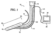
図1〜3を参照して、本発明にしたがって構成された例示的なLMAデバイスが説明される。LMAデバイス10は、説明的に喉頭マスク気道であり、マスク部分12に結合された柔軟な気道チューブ11を含む。
With reference to FIGS. 1-3, an exemplary LMA device constructed in accordance with the present invention will be described. The
従来のように、気道チューブ11は、患者の気道にしたがうように曲げられており柔軟であり、マスク部分12のボウル形状の下部表面14における開口部13と連通している。気道チューブ11は、チューブを呼吸デバイスに結合するコネクタ15を含む。マスク部分12は、マスク部分の周囲に沿って配置されたカフ16を含む。カフ16は、概ね楕円形状、涙滴形状、または他の適切な形状を有する。カフ16は、エラストマー材料からなり、空気を除去または追加することによってカフが挿入のために収縮させられたり展開されたりすることを可能にするチュービング17を含む。カフ16は、喉頭の背後のスペースに整合し、その中に容易にフィットするように構成されており、それによって喉頭入口の周縁のあたりに密封を形成する。
As is conventional, the
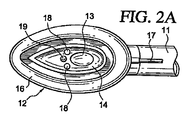
LMAデバイス10は、少なくとも一つのビデオセンサ18をさらに含む。ビデオセンサ18は、好ましくは、デジタルビデオカメラに使用されるような電荷結合デバイス(CCD)、もしくはCMOSまたはNMOSイメージセンサのいずれかである。ビデオセンサ18は、多数の半導体チップ製造プロセスのいずれかを使用して製造され得る。ビデオセンサ18は、マスク部分12に搭載される。ビデオセンサ18は、LMAデバイスが患者の喉の中に挿入されるときに、視野が、開口部13と位置合わせされ、喉頭入口または他の所望の気道構造を含むように、方向付けられる。オプションとして、マスク部分12はまた、LMAデバイス10を配置してカフ16を展開する間に患者の気道を照明するために、発光ダイオード(LED)などの照明源19を含み得る。
The
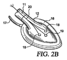
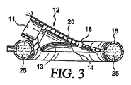
図1〜3に示される説明的な実施形態において、マスク部分12は、2つのビデオセンサ18を含み、ビデオセンサ18は、その間に配置された照明源19を有する。有利なことに、ビデオセンサ18は、それらの視野が重なり合うことによって臨床医に立体視を提供するように方向付けられる。図3に示されるように、各ビデオセンサ18は、好ましくは、マスク部分12の壁に埋め込まれるかまたは穴埋めされ、光学的にクリアなウィンドウを有するプラスチックハウジングに配置されたCCD、CMOS、またはNMOSチップを備える。一つのみのビデオセンサの使用が本発明の範囲内であり、センサによって提供される視野を最適化するために、マスク部分の中に一つのビデオセンサを位置付けることが選択され得ることが理解されるべきである。
In the illustrative embodiment shown in FIGS. 1-3, the
好ましい実施形態において、ビデオセンサ18は、約4〜5cmの焦点距離を有する。代替的には、ビデオセンサ18は、レンズを使用して達成され得るような焦点合わせ機能を有し得る。ビデオセンサ18は、好ましくは少なくとも70度の、より好ましくは100〜120度の視野を提供する。
In a preferred embodiment,
ビデオセンサ18および照明源19は、コネクタ21において終結する電気リード20を介して結合されている。電気リード20は、気道チューブ11の外部表面に取り付けられた非導電チューブの中に配置されるか、または代替的に、気道チューブ11の壁における内部管腔の中に配置され得る。コネクタ21は、組合せコネクタ22に結合され得、組合せコネクタ22は次に、処理ユニット23およびディスプレイ画面24に結合される。
処理ユニット23は、ビデオセンサ18および照明源19に電力を供給し、ビデオセンサ18によって生成される信号を、画面24上に表示され得るビデオ画像に変換する。このようにして、臨床医は、ビデオセンサ18から処理ユニット23およびディスプレイ24に供給されるビデオによって案内されて、LMAデバイスを挿入し得、それによって、LMAデバイスのマスク部分12の最適な配置を達成する。ビデオセンサに電力を供給してそのようなセンサの出力をビデオ画像に変換する処理ユニット23は、当該技術分野において公知であり、デジタルビデオカムコーダーにおいて一般に使用されているタイプのものであり得る。ディスプレイ画面24は、任意の適切なビデオディスプレイを備え得、処理ユニット23と一体であるかまたは分離されているかのいずれかであり得る。代替的には、LMAデバイスは、バッテリなどのオンボード電源を含み得、電源は、LMAデバイスの気道チューブまたはマスク部分に都合良く配置されることによって、ビデオセンサまたは照明源に電源を供給する。後者の場合には、処理ユニットは、ビデオセンサによって出力される信号を受け取り、そのデータを画面24上の表示のためのデジタル画像に変換するだけで良い。
The processing unit 23 supplies power to the
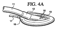
ここで図3および図4を参照すると、カフ16は、従来の構成であり得、加圧された気体(たとえば空気)または液体を使用して膨張によって展開されるエラストマー材料からなり得る。しかし、好ましい実施形態において、カフ16は連続気泡発泡体25によって満たされる。連続気泡発泡体は、排気されるときには小さな体積に圧縮され得(図4B)、展開されるときには喉頭入口に整合し喉頭入口を密封するように再び膨張する(図4A)。連続気泡発泡体25のための一つの好ましい材料は、連続気泡ポリエチレン発泡体である。
Referring now to FIGS. 3 and 4, the
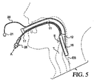
ここで図5も参照すると、操作において、カフ16はチュービング17を介して発泡体から空気を押し出すように圧縮され、チュービングは次に、取り外し可能なプラグ26によって密封される。カフ16はまた、図4Bに示されるように、圧縮されるときにはマスク部分の周囲が上に折りたたまれ得、その結果、マスクの周囲はLMAデバイスの挿入を妨げない。マスク部分12は、次に、患者の口を通して挿入され、患者の食道ESのすぐ上に配置され、その結果、ビデオセンサ18を使用してビデオ案内によって決定されるように、マスク部分12の開口部13は、喉頭蓋Eの下に、患者の喉頭入口と位置合わせされて配置される。ひとたびLMAデバイスが喉頭入口を取り囲むように配置されると、矢印Aによって示されるように、プラグ26が開いて、空気がチュービング17の中に流れることを可能にする。図4Aに示されるように、このことは、次に、発泡体25が再び膨張して喉頭入口のあたりを密封することを可能にし、呼吸を可能にし、胃の流動物が患者の肺の中に吸い込まれることを防止する。
Referring now also to FIG. 5, in operation, the
本発明のLMAデバイスは、マスクの位置を即座に光学的に確認することを可能にし、そのことは次に、少なくとも以下のさらなる利点を提供する:
−気管の挿管が完了する前に、マスク部分12のボウルにおける逆流液体の存在は、肺の重大な汚染が発生する前に即座に見られて吸引カテーテルを使用して吸引され得る。
−ビデオセンサからの視覚的情報は、たとえば麻酔器上の監視機器の一部として、遠隔観察のためにテレビ画面に転送され得る。
−ビデオセンサによって提供されるビデオ画像は、たとえば法医学的証拠のために、将来の教示に使用するための、または患者の症例ノートの一部として使用されるために、格納され得る。
−不適切なレベルの麻酔を示す喉頭の運動が観察され得、それによって早期の介入を可能にし、喉頭痙攣または覚醒の危険を低減する。
−電気的刺激に起因する喉頭の運動が容易に監視され得ることによって、喉頭神経機能を保護する。
−かねてより公知のLMAと同様に、デバイスは、喉への局部麻酔の適用後に、覚醒した患者に挿入され得、それによって外来患者ベースで上部気道の問題の治療および診断の可能性を提供する。
The LMA device of the present invention allows for instant optical confirmation of the position of the mask, which in turn provides at least the following further advantages:
-Before the tracheal intubation is complete, the presence of reflux liquid in the bowl of the
-Visual information from the video sensor can be transferred to a television screen for remote viewing, eg as part of a monitoring device on the anesthesia machine.
-The video image provided by the video sensor may be stored, eg for forensic evidence, for use in future teachings or for use as part of a patient case note.
-Laryngeal movements showing an inappropriate level of anesthesia can be observed, thereby allowing early intervention and reducing the risk of laryngeal spasms or arousal.
Protect laryngeal nerve function by allowing laryngeal movements due to electrical stimulation to be easily monitored.
-Like the previously known LMA, the device can be inserted into an awake patient after the application of local anesthesia to the throat, thereby providing the possibility of treatment and diagnosis of upper airway problems on an outpatient basis .
ここで図6および図7を参照して、本発明のLMAデバイスの代替的な実施形態、説明的に挿管喉頭マスク(「ILM」)が説明される。図6に示されるILMは、LMA North America,Inc.によって「LMA−Fastrach(登録商標)」という商品名で市販されているものに設計が類似しており、マスク部分32に取り付けられた曲げられた気道チューブ31を備える。マスク部分32は、概ね楕円形のカフ33によってその周囲が囲まれている。マスク部分32およびカフ33は、上述のように、従来の構造および構成であり、オプションとして喉頭蓋上昇バー34を含み得る。加圧された気体が、チュービング35を使用して、弁36およびパイロットバルーン37を介して、カフ33に供給され、カフ33から引き抜かれる。
With reference now to FIGS. 6 and 7, an alternative embodiment of the LMA device of the present invention, illustratively an intubated laryngeal mask (“ILM”) will be described. The ILM shown in FIG. 6 is available from LMA North America, Inc. Is similar in design to that marketed under the trade name “LMA-Fastrach®” and comprises a
気道チューブ31は、柔軟なプラスチックの被覆を備え、該被覆は、外部の硬いハンドル39からマスク部分32のボウルまで延びる金属チューブ38を覆うように配置されている。気道チューブは、メイン気道管腔40を含み、メイン気道管腔は、開口部41を介してマスク部分32のボウルと連通している。ハンドル39の延長は、ILMを患者の喉に位置付けて操作するために使用される。気道チューブ31には、従来の麻酔ガスホースに取り付けるために設計された、容易に取り外し可能な摩擦ばめコネクタ(図示せず)が提供されており、その結果、気管内チューブで患者に挿管することなく、デバイスは患者の肺を換気するためにスタンドアロンの態様で使用され得る。
The
本発明の原理に従って、ILMは、マスク部分32のボウル内に配置されたビデオセンサ42および照明源43を含む。上述のように、ビデオセンサ42は、好ましくはCCD、CMOS、またはNMOSデバイスを備え、照明源43は、好ましくはLEDを備える。ビデオセンサ42および照明源43は、電気リード44を介してコネクタ45に結合されており、コネクタ45は処理ユニットに結合され得、その結果、図1に関して上述されたように、ビデオセンサ42によって生成された信号は、デジタル画像に変換され得、ディスプレイ画面に表示され得る。
In accordance with the principles of the present invention, the ILM includes a
ビデオセンサ42は、好ましくは、喉頭の視野を提供するような角度でマスク部分の開口部41に近いマスク部分32のボウル内に配置され、より好ましくは、喉頭の立体視を提供するためにビデオセンサの視野が重なり合うように配置される。このようにして、気管内チューブを気管に挿管することが望まれる場合には、図7に示されるように、ビデオセンサからの喉頭の視野は、臨床医が気管内チューブの先端を喉頭の入口に向けて案内することを援助するために使用され得る。さらに、ILMは、ハンドル39を使用して操作され得ることによって、マスク部分32の開口部41と喉頭の入口との間の位置合わせを改善する。
The
図7において、図6のILMが、患者の喉の中でカフ33を展開して配置され、マスク部分32が喉頭の入口を取り囲んで密封していることが示されている。示されるように、ひとたびILMが配置されると、ILMの近位端が間欠的に呼吸システムに結合され得ることによって、患者に陽圧呼吸(positive ventilation)を提供する。気管内チューブ50を患者に挿管することが望まれる場合には、呼吸システムからの気体ホース(図示せず)が取り外され得、気管内チューブ50が、気道チューブ31の管腔40を通して挿入される。ビデオセンサ42によって生成されるビデオ画像を使用して、臨床医は、次に、ハンドル39を操作することによって、気管内チューブの先端を患者の気管の中に案内する。
In FIG. 7, the ILM of FIG. 6 is shown deployed with the
図8において、代替的な実施形態が示され、ビデオセンサ18’が気道チューブ11’の内部に配置されている。図1〜3のLMAデバイスの同様のパーツは、図8において同様のダッシュつきの(prime)数字によって示される。したがって、図1のチュービング17は、図8においてチュービング17’として示される。
In FIG. 8, an alternative embodiment is shown in which a video sensor 18 'is placed inside the airway tube 11'. Similar parts of the LMA device of FIGS. 1-3 are indicated by similar primed numbers in FIG. Accordingly, the
デバイス10’は、反射面51を備え、反射面51は、ビデオセンサ18’と開口部13’との間に光学的に配置されている。したがって、デバイス10’の遠位端から入る光線は、表面51によって反射されて、ビデオセンサ18’に向けられる。反射面51は、好ましくは鏡を備えるが、代替的には、プリズム、レンズ、または他の公知の光学デバイスを備え得る。オプションとして、複数の反射面51が使用され得る。ビデオセンサ18’は、気道チューブ11に沿った種々の位置に配置され得ることが理解される。
The device 10 'includes a
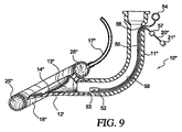
ここで図9を参照して、デバイス10”が説明され、図1〜3の同様のパーツは、図9において同様のダブルダッシュつきの(double−prime)数字によって示される。したがって、たとえば図1のチュービング17は、図9においてチュービング17”として示される。
Referring now to FIG. 9, a
ビデオセンサ52は、開口部13”の近くに配置され、ユーザ操作を可能にするように構成されている。具体的には、ビデオセンサ52は、ピボット53上に搭載され、部材55によってハンドル54に接続されている。本発明の一つの局面に従って、部材55は、ビデオセンサ52に力を伝えることができるワイヤである。したがって、ユーザは、ハンドル54を押したり引いたりすることによって、ピボット53上でビデオセンサ52を回転させて、ビデオセンサ52の視野を変化させ得る。他の実施形態において、たとえば、ビデオセンサ52の操作は、ビデオセンサ52がデバイス10”の長さの部分に沿って移動することを可能にすることによって達成され得る。パースペクティブ(perspective)の観察を操作する他のモードが提供され得ることが理解される。同様に、部材55が気道チューブ11”の壁のアパーチャ56を通過する場合には、換気される空気の望ましくない損失を防止するために、アパーチャ56は密封されるべきかまたは十分に小さくあるべきである。
The video sensor 52 is disposed near the
気道チューブ11”の閉塞を最小限にするために、ビデオセンサ52のコンポーネントは、イメージングデバイスの限定された部分を含み得る。たとえば、イメージングデバイスが、ピクセルアレイと処理回路網とを備えるCMOSチップである場合には、ビデオセンサ52は、ピクセルアレイを備え得るが、関連する(associated)回路網はハウジング57内に配置され得る。ハウジング57はリード58を介してビデオセンサ52に結合されているが、これらのコンポーネントは互いに距離を置いて配置されている。好ましくは、ハウジング57はデバイス10”の近位端の近くに配置され、患者の呼吸を大きく妨げない。
In order to minimize blockage of the
有利なことに、本発明の特徴は、喉頭マスクデバイスの任意の形状に組み込まれ得、上述の例示的な実施形態に限定されない。本発明から逸脱することなく、そこに(therein)種々の変更および改変がなされ得ることが当業者にとって自明である。添付の特許請求の範囲において、本発明の精神および範囲内にあるすべてのそのような変更および改変をカバーすることが意図される。 Advantageously, the features of the present invention can be incorporated into any shape of the laryngeal mask device and are not limited to the exemplary embodiments described above. It will be apparent to those skilled in the art that various changes and modifications can be made there without departing from the invention. The appended claims are intended to cover all such changes and modifications as fall within the spirit and scope of the invention.
Claims (30)
近位端と遠位端とを有する気道チューブと、
該気道チューブの該遠位端に取り付けられたマスク部分と、
該マスク部分の周囲に配置されたカフであって、該カフは該患者の喉頭入口の周縁のあたりに密封を形成するように構成されている、カフと、
該喉頭マスク気道デバイスに永久に結合された第1のデジタルビデオセンサであって、該第1のビデオセンサは、該マスク部分の配置の視覚的な確認を提供するために、該患者の喉頭入口を含む視野を有する、第1のデジタルビデオセンサと
を備える、喉頭マスク気道デバイス。 A laryngeal mask airway device that facilitates pulmonary breathing of a patient, the device comprising:
An airway tube having a proximal end and a distal end;
A mask portion attached to the distal end of the airway tube;
A cuff disposed around the mask portion, the cuff being configured to form a seal around the periphery of the patient's laryngeal inlet;
A first digital video sensor permanently coupled to the laryngeal mask airway device, wherein the first video sensor provides a visual confirmation of the placement of the mask portion to the patient's laryngeal inlet A laryngeal mask airway device comprising: a first digital video sensor having a field of view comprising:
管腔と近位端と遠位端とを有する気道チューブと、
該気道チューブの該遠位端に取り付けられたマスク部分であって、該マスク部分は、該気道チューブの該管腔と連通する開口部を有する、マスク部分と、
該マスク部分の周囲のあたりに配置されたカフであって、該カフは、収縮した送出状態と、膨張した展開状態とを有し、該カフは、該患者の喉頭入口の周縁のあたりに密封を形成する、カフと、
該喉頭マスク気道デバイスに永久に結合された第1のデジタルビデオセンサであって、該第1のデジタルビデオセンサは、該患者の気道の内部の該マスク部分に配置された後に、該患者の気道の中の所望の視野を有する、第1のデジタルビデオセンサと
を備える、喉頭マスク気道デバイス。 A laryngeal mask airway device that facilitates pulmonary breathing of a patient, the device comprising:
An airway tube having a lumen, a proximal end, and a distal end;
A mask portion attached to the distal end of the airway tube, the mask portion having an opening in communication with the lumen of the airway tube;
A cuff disposed about the perimeter of the mask portion, the cuff having a deflated delivery state and an inflated deployed state, the cuff sealing around the periphery of the patient's laryngeal inlet Forming a cuff,
A first digital video sensor permanently coupled to the laryngeal mask airway device, wherein the first digital video sensor is disposed on the mask portion within the patient's airway and then the patient's airway A laryngeal mask airway device comprising: a first digital video sensor having a desired field of view.
Applications Claiming Priority (2)
| Application Number | Priority Date | Filing Date | Title |
|---|---|---|---|
| US11/044,559 US20060162730A1 (en) | 2005-01-26 | 2005-01-26 | Video-assisted laryngeal mask airway devices |
| PCT/US2006/002710 WO2006081326A1 (en) | 2005-01-26 | 2006-01-25 | Video-assisted laryngeal mask airway devices |
Publications (1)
| Publication Number | Publication Date |
|---|---|
| JP2008528131A true JP2008528131A (en) | 2008-07-31 |
Family
ID=36695403
Family Applications (1)
| Application Number | Title | Priority Date | Filing Date |
|---|---|---|---|
| JP2007552404A Pending JP2008528131A (en) | 2005-01-26 | 2006-01-25 | Video-assisted laryngeal mask airway device |
Country Status (7)
| Country | Link |
|---|---|
| US (2) | US20060162730A1 (en) |
| EP (1) | EP1841480A1 (en) |
| JP (1) | JP2008528131A (en) |
| CN (1) | CN101374565A (en) |
| AU (1) | AU2006208080A1 (en) |
| CA (1) | CA2595604A1 (en) |
| WO (1) | WO2006081326A1 (en) |
Cited By (5)
| Publication number | Priority date | Publication date | Assignee | Title |
|---|---|---|---|---|
| KR101341353B1 (en) | 2012-01-30 | 2013-12-18 | 전덕규 | Facial mask and endotracheal intubation system using the same |
| JP2016516455A (en) * | 2013-03-06 | 2016-06-09 | メディコム フロー,ソシエダ アノニマ | A laryngeal video mask with an inflexible retractable tongue and means for ventilation and intubation |
| JP2017528194A (en) * | 2014-08-08 | 2017-09-28 | ダブリューエム・アンド・ディージー,インク | Medical device and its mounting |
| JP2019502478A (en) * | 2016-01-07 | 2019-01-31 | グレン・ピー・ガードナー | Endotracheal tube insertion device |
| JP2022520042A (en) * | 2019-02-02 | 2022-03-28 | チャンサ マギル メディカル テクノロジー カンパニー リミテッド | Laryngeal mask |
Families Citing this family (58)
| Publication number | Priority date | Publication date | Assignee | Title |
|---|---|---|---|---|
| US10549055B2 (en) * | 2005-03-25 | 2020-02-04 | Airguard, Llc | Medical apparatus with hypopharyngeal suctioning capability |
| FR2892636B1 (en) * | 2005-11-03 | 2008-04-18 | Bruno Bassoul | "LARYNGE MASK SUITABLE FOR THE INTRODUCTION AND RELEASE OF AN INTUBATION PROBE." |
| GB0526350D0 (en) * | 2005-12-23 | 2006-02-01 | Trucorp Ltd | Laryngeal mask device |
| WO2008019367A2 (en) * | 2006-08-07 | 2008-02-14 | Innovative Medical Devices, Inc. | System to aid in the positioning, confirmation and documentation of an endotracheal tube |
| EP2014326A1 (en) * | 2007-07-12 | 2009-01-14 | Tien-Sheng Chen | Laryngeal mask airway with a force application structure, operating piece for controlling the same, and gas supply kit comprising the same |
| CA2625548C (en) | 2007-08-04 | 2012-04-10 | John A. Law | An airway intubation device |
| US8166967B2 (en) * | 2007-08-15 | 2012-05-01 | Chunyuan Qiu | Systems and methods for intubation |
| WO2009025843A1 (en) * | 2007-08-20 | 2009-02-26 | Samir Bhatt | Laryngeal airway nerve monitor |
| US9119926B2 (en) | 2009-07-31 | 2015-09-01 | Avent, Inc. | Subglottic suctioning system |
| US9179831B2 (en) | 2009-11-30 | 2015-11-10 | King Systems Corporation | Visualization instrument |
| EP2560719B1 (en) | 2010-02-27 | 2018-07-04 | King Systems Corporation | Laryngeal tube |
| US9795753B2 (en) | 2012-03-07 | 2017-10-24 | Chunyuan Qiu | Intubation delivery systems and methods |
| US8894569B2 (en) | 2010-04-21 | 2014-11-25 | Chunyuan Qiu | Intubation systems and methods based on airway pattern identification |
| US9289114B2 (en) * | 2010-07-30 | 2016-03-22 | Nilesh R. Vasan | Disposable, self-contained laryngoscope and method of using same |
| US8667966B2 (en) | 2010-08-03 | 2014-03-11 | Hideo Koike | Intubating attachment and method |
| DE102010051882B4 (en) * | 2010-11-22 | 2022-12-22 | Blazejewski Medi-Tech Gmbh | 3D video endoscope |
| US20120172847A1 (en) * | 2010-12-30 | 2012-07-05 | Hooper Nicholas W | Vacuum assist device to remove object from trachea |
| WO2012127435A1 (en) * | 2011-03-23 | 2012-09-27 | Donald Munro Miller | Oral surgery laryngeal mask device |
| EP2535075A1 (en) | 2011-06-15 | 2012-12-19 | Medizinische Hochschule Hannover | Medical device for conducting a laryngoscopy and/or an intubation |
| CN102266627A (en) * | 2011-08-10 | 2011-12-07 | 山东峰源医用材料有限公司 | Multifunctional luminous trachea cannula |
| TWM429482U (en) * | 2011-09-09 | 2012-05-21 | Tien-Sheng Chen | Tracheal intubation device |
| CN102580198A (en) * | 2011-12-29 | 2012-07-18 | 中国人民解放军第三军医大学第一附属医院 | Accurate-positioned double-tube laryngeal mask |
| US9415179B2 (en) | 2012-06-01 | 2016-08-16 | Wm & Dg, Inc. | Medical device, and the methods of using same |
| US9357905B2 (en) * | 2012-06-01 | 2016-06-07 | Robert Molnar | Airway device, airway assist device and the method of using same |
| CN102920422B (en) * | 2012-10-26 | 2016-05-11 | 西安索格医疗科技有限公司 | Visual vented cannula laryngoscope |
| WO2014089519A1 (en) | 2012-12-07 | 2014-06-12 | Bartlett Ii Rush L | System for reducing local discomfort |
| KR102023189B1 (en) | 2013-07-03 | 2019-09-20 | 삼성전자주식회사 | Sound generation apparatus and electric apparatus comprising thereof |
| US11000658B2 (en) | 2014-05-18 | 2021-05-11 | Awair, Inc. | Device to reduce discomfort in the upper airway |
| US11633093B2 (en) | 2014-08-08 | 2023-04-25 | Wm & Dg, Inc. | Medical devices and methods of placement |
| US11147442B2 (en) | 2014-08-08 | 2021-10-19 | Wm & Dg, Inc. | Medical devices and methods of placement |
| US9918618B2 (en) | 2014-08-08 | 2018-03-20 | Wm & Dg, Inc. | Medical devices and methods of placement |
| WO2016179563A1 (en) | 2015-05-07 | 2016-11-10 | Ecom Medical, Inc. | Systems and methods for internal ecg acquisition |
| CN104922773B (en) * | 2015-06-24 | 2018-01-12 | 北京信安远望技术开发有限公司 | Multitube laryngeal mask |
| KR102548901B1 (en) * | 2015-11-13 | 2023-06-29 | 삼성전자주식회사 | Telelens and Imaging Device |
| US10478054B2 (en) | 2016-02-12 | 2019-11-19 | Ambu A/S | Endotracheal tube with visualization capabilities and a laryngeal mask |
| US11147515B2 (en) | 2016-02-16 | 2021-10-19 | Ecom Medical, Inc. | Systems and methods for obtaining cardiovascular parameters |
| US20180169365A1 (en) * | 2016-12-21 | 2018-06-21 | University Of Washington | Intubating Neonatal Laryngeal Mask Airway |
| US11051682B2 (en) | 2017-08-31 | 2021-07-06 | Wm & Dg, Inc. | Medical devices with camera and methods of placement |
| WO2019153803A1 (en) * | 2018-02-07 | 2019-08-15 | 浙江优亿医疗器械有限公司 | Improved video laryngeal mask |
| CN108211062A (en) * | 2018-02-07 | 2018-06-29 | 浙江优亿医疗器械有限公司 | A kind of improved visual laryngeal mask |
| CN108653890B (en) * | 2018-05-18 | 2024-06-28 | 浙江简成医疗科技有限公司 | Visual laryngeal mask |
| USD858752S1 (en) | 2018-05-21 | 2019-09-03 | Sridhar R. Musuku | Intubation device |
| US10596339B2 (en) | 2018-05-21 | 2020-03-24 | Sridhar R. Musuku | Intubation devices and methods of use |
| USD876625S1 (en) | 2018-08-07 | 2020-02-25 | Adroit Surgical, Llc | Laryngoscope |
| US10653307B2 (en) | 2018-10-10 | 2020-05-19 | Wm & Dg, Inc. | Medical devices for airway management and methods of placement |
| US12257387B2 (en) | 2018-10-10 | 2025-03-25 | Wm & Dg, Inc. | Medical devices for airway management and methods of placement |
| EP3890814B1 (en) * | 2018-12-06 | 2024-03-13 | Chiesi Farmaceutici S.p.A. | Laryngeal mask airway device and method for administering a medicament through a laryngeal mask airway device |
| USD921185S1 (en) * | 2019-01-24 | 2021-06-01 | Sridhar R. Musuku | Intubation device |
| TWM579040U (en) * | 2019-01-25 | 2019-06-11 | 單志宏 | Improved structure for laryngeal mask airway |
| CN110292690A (en) * | 2019-02-02 | 2019-10-01 | 长沙迈吉尔医疗科技有限公司 | Connector, laryngeal mask main body and the laryngeal mask of laryngeal mask |
| CN111514420B (en) * | 2019-02-02 | 2024-02-02 | 李大庆 | Laryngeal mask and laryngeal mask body and far-end visual accommodation structure thereof |
| CN110292689B (en) * | 2019-02-02 | 2021-07-30 | 长沙迈吉尔医疗科技有限公司 | Laryngeal mask |
| CN111514419B (en) * | 2019-02-02 | 2023-08-04 | 李大庆 | Far-end subassembly and have its laryngeal mask main part, laryngeal mask are held to video |
| CN110201300B (en) * | 2019-06-06 | 2020-08-25 | 北京航空航天大学 | A device for the treatment of bronchospasm |
| US11357395B2 (en) | 2019-07-01 | 2022-06-14 | Robert B Maximos | Tracheoscope control device, laryngeal mask airway device, and combination system thereof |
| CN110575592B (en) * | 2019-09-25 | 2024-08-23 | 夏敏 | Laryngeal mask with monitoring of perilaryngeal muscle relaxation and monitoring of regurgitation |
| US11497394B2 (en) | 2020-10-12 | 2022-11-15 | Wm & Dg, Inc. | Laryngoscope and intubation methods |
| GB2611046B (en) * | 2021-09-23 | 2023-10-25 | Willmott Orthopaedics Ltd | Laryngeal mask airway |
Citations (2)
| Publication number | Priority date | Publication date | Assignee | Title |
|---|---|---|---|---|
| US5682880A (en) * | 1996-07-26 | 1997-11-04 | Brain; Archibald Ian Jeremy | Laryngeal-mask airway with guide element, stiffener, and fiberoptic access |
| US6929600B2 (en) * | 2001-07-24 | 2005-08-16 | Stephen D. Hill | Apparatus for intubation |
Family Cites Families (17)
| Publication number | Priority date | Publication date | Assignee | Title |
|---|---|---|---|---|
| GB2111394B (en) * | 1981-12-16 | 1985-09-11 | Archibald Ian Jeremy Brain | Artificial airway device |
| US4846153A (en) * | 1988-06-10 | 1989-07-11 | George Berci | Intubating video endoscope |
| GB2229367A (en) * | 1989-03-22 | 1990-09-26 | Archibald Ian Jeremy Brain | Artificial airway device |
| US5285778A (en) * | 1991-04-19 | 1994-02-15 | Mackin Robert A | Endotracheal tube wih fibers optic illumination and viewing and auxiliary tube |
| US5297547A (en) * | 1992-07-30 | 1994-03-29 | Brain Archibald Ian Jeremy | Laryngeal mask construction |
| US5355879A (en) * | 1992-09-28 | 1994-10-18 | Brain Archibald Ian Jeremy | Laryngeal-mask construction |
| US5363838B1 (en) * | 1992-12-09 | 2000-03-28 | Gordon P George | Fiberoptic intubating scope with camera and lightweight portable screen and method of using same |
| US5623921A (en) * | 1996-04-10 | 1997-04-29 | Kinsinger; J. William | Laryngeal mask airway and method for its use |
| US5827178A (en) * | 1997-01-02 | 1998-10-27 | Berall; Jonathan | Laryngoscope for use in trachea intubation |
| US5988167A (en) * | 1997-05-02 | 1999-11-23 | Kamen; Jack M. | Foam cuff for laryngeal mask airway |
| GB9817537D0 (en) * | 1998-08-13 | 1998-10-07 | Brain Archibald Ian Jeremy | A laryngear mask airway with mutually independant laterally-placed ultra-flexible eastric access/discharge and airway tubes |
| US6217514B1 (en) * | 1999-02-05 | 2001-04-17 | Gruhan Technologies, Inc. | Laryngoscope |
| US6257236B1 (en) * | 1999-02-23 | 2001-07-10 | Edward P Dutkiewicz | Intubation device |
| US6652453B2 (en) * | 1999-03-03 | 2003-11-25 | Vincent A. Smith | Portable video laryngoscope |
| US6705318B1 (en) * | 1999-04-09 | 2004-03-16 | Archibald I. J. Brain | Disposable LMA |
| US6626169B2 (en) * | 2001-05-17 | 2003-09-30 | Elisha Medical Technologies Ltd. | Anatomical airway ventilation intubating and resuscitation device |
| US6840903B2 (en) * | 2002-03-21 | 2005-01-11 | Nuvista Technology Corporation | Laryngoscope with image sensor |
-
2005
- 2005-01-26 US US11/044,559 patent/US20060162730A1/en not_active Abandoned
-
2006
- 2006-01-25 CN CNA2006800065781A patent/CN101374565A/en active Pending
- 2006-01-25 US US11/340,383 patent/US20060180155A1/en not_active Abandoned
- 2006-01-25 EP EP06719538A patent/EP1841480A1/en not_active Withdrawn
- 2006-01-25 WO PCT/US2006/002710 patent/WO2006081326A1/en not_active Ceased
- 2006-01-25 JP JP2007552404A patent/JP2008528131A/en active Pending
- 2006-01-25 AU AU2006208080A patent/AU2006208080A1/en not_active Abandoned
- 2006-01-25 CA CA002595604A patent/CA2595604A1/en not_active Abandoned
Patent Citations (2)
| Publication number | Priority date | Publication date | Assignee | Title |
|---|---|---|---|---|
| US5682880A (en) * | 1996-07-26 | 1997-11-04 | Brain; Archibald Ian Jeremy | Laryngeal-mask airway with guide element, stiffener, and fiberoptic access |
| US6929600B2 (en) * | 2001-07-24 | 2005-08-16 | Stephen D. Hill | Apparatus for intubation |
Cited By (10)
| Publication number | Priority date | Publication date | Assignee | Title |
|---|---|---|---|---|
| KR101341353B1 (en) | 2012-01-30 | 2013-12-18 | 전덕규 | Facial mask and endotracheal intubation system using the same |
| US9572946B2 (en) | 2012-01-30 | 2017-02-21 | Dukkyu Chun | Facial mask and endotracheal intubation system |
| JP2016516455A (en) * | 2013-03-06 | 2016-06-09 | メディコム フロー,ソシエダ アノニマ | A laryngeal video mask with an inflexible retractable tongue and means for ventilation and intubation |
| JP2017528194A (en) * | 2014-08-08 | 2017-09-28 | ダブリューエム・アンド・ディージー,インク | Medical device and its mounting |
| JP2019502478A (en) * | 2016-01-07 | 2019-01-31 | グレン・ピー・ガードナー | Endotracheal tube insertion device |
| JP7008628B2 (en) | 2016-01-07 | 2022-01-25 | グレン・ピー・ガードナー | Endotracheal tube insertion device |
| JP2022058549A (en) * | 2016-01-07 | 2022-04-12 | グレン・ピー・ガードナー | Endotracheal tube insertion device |
| JP7133111B2 (en) | 2016-01-07 | 2022-09-07 | グレン・ピー・ガードナー | Endotracheal tube insertion device |
| JP2022520042A (en) * | 2019-02-02 | 2022-03-28 | チャンサ マギル メディカル テクノロジー カンパニー リミテッド | Laryngeal mask |
| JP7250151B2 (en) | 2019-02-02 | 2023-03-31 | チャンサ マギル メディカル テクノロジー カンパニー リミテッド | laryngeal mask |
Also Published As
| Publication number | Publication date |
|---|---|
| WO2006081326B1 (en) | 2008-05-15 |
| WO2006081326A1 (en) | 2006-08-03 |
| US20060162730A1 (en) | 2006-07-27 |
| EP1841480A1 (en) | 2007-10-10 |
| US20060180155A1 (en) | 2006-08-17 |
| CA2595604A1 (en) | 2006-08-03 |
| CN101374565A (en) | 2009-02-25 |
| AU2006208080A1 (en) | 2006-08-03 |
Similar Documents
| Publication | Publication Date | Title |
|---|---|---|
| JP2008528131A (en) | Video-assisted laryngeal mask airway device | |
| JP3738278B2 (en) | Laringel mask airway that can be intubated by optical fiber | |
| US10478054B2 (en) | Endotracheal tube with visualization capabilities and a laryngeal mask | |
| EP1551277B1 (en) | Endotracheal tube with an imaging sensor | |
| CN105050481B (en) | With scalable rigid tongue and for the laryngeal mask for the instrument ventilated and be intubated | |
| US20150173598A1 (en) | Intubating Airway | |
| JP2013510699A (en) | Channel laryngoscope and system | |
| JP2007532218A5 (en) | ||
| US20160250432A1 (en) | Method and apparatus for multi-camera intubation | |
| JP2015016177A (en) | Medical instrument | |
| WO2024108225A2 (en) | Intelligent laryngeal mask airway device with visualization | |
| AU2013239345A1 (en) | Endotracheal tube introducer | |
| US20250072741A1 (en) | Video laryngoscopic tracheoscope | |
| CN111514421B (en) | Laryngeal mask airway and video device | |
| HK1216493B (en) | Laryngeal mask with retractable rigid tab and means for ventilation and intubation |
Legal Events
| Date | Code | Title | Description |
|---|---|---|---|
| A131 | Notification of reasons for refusal |
Free format text: JAPANESE INTERMEDIATE CODE: A131 Effective date: 20100105 |
|
| A601 | Written request for extension of time |
Free format text: JAPANESE INTERMEDIATE CODE: A601 Effective date: 20100402 |
|
| A602 | Written permission of extension of time |
Free format text: JAPANESE INTERMEDIATE CODE: A602 Effective date: 20100409 |
|
| A601 | Written request for extension of time |
Free format text: JAPANESE INTERMEDIATE CODE: A601 Effective date: 20100430 |
|
| A602 | Written permission of extension of time |
Free format text: JAPANESE INTERMEDIATE CODE: A602 Effective date: 20100512 |
|
| A02 | Decision of refusal |
Free format text: JAPANESE INTERMEDIATE CODE: A02 Effective date: 20100727 |