JP2009005662A - Thresher - Google Patents
Thresher Download PDFInfo
- Publication number
- JP2009005662A JP2009005662A JP2007172368A JP2007172368A JP2009005662A JP 2009005662 A JP2009005662 A JP 2009005662A JP 2007172368 A JP2007172368 A JP 2007172368A JP 2007172368 A JP2007172368 A JP 2007172368A JP 2009005662 A JP2009005662 A JP 2009005662A
- Authority
- JP
- Japan
- Prior art keywords
- cover
- plate
- handling chamber
- gap
- guide
- Prior art date
- Legal status (The legal status is an assumption and is not a legal conclusion. Google has not performed a legal analysis and makes no representation as to the accuracy of the status listed.)
- Pending
Links
- 241000251169 Alopias vulpinus Species 0.000 title 1
- 235000013339 cereals Nutrition 0.000 claims abstract description 17
- 239000000463 material Substances 0.000 claims description 2
- 238000006073 displacement reaction Methods 0.000 claims 1
- 239000004071 soot Substances 0.000 abstract description 7
- 239000000428 dust Substances 0.000 abstract description 5
- 238000009825 accumulation Methods 0.000 abstract description 2
- 239000010902 straw Substances 0.000 description 5
- 230000005540 biological transmission Effects 0.000 description 4
- 230000002265 prevention Effects 0.000 description 4
- 238000012423 maintenance Methods 0.000 description 3
- 230000013011 mating Effects 0.000 description 3
- 239000002699 waste material Substances 0.000 description 3
- XEEYBQQBJWHFJM-UHFFFAOYSA-N Iron Chemical compound [Fe] XEEYBQQBJWHFJM-UHFFFAOYSA-N 0.000 description 2
- 230000003014 reinforcing effect Effects 0.000 description 2
- BZHJMEDXRYGGRV-UHFFFAOYSA-N Vinyl chloride Chemical compound ClC=C BZHJMEDXRYGGRV-UHFFFAOYSA-N 0.000 description 1
- 238000005452 bending Methods 0.000 description 1
- 230000000694 effects Effects 0.000 description 1
- 229910052742 iron Inorganic materials 0.000 description 1
- 239000000725 suspension Substances 0.000 description 1
- 239000013585 weight reducing agent Substances 0.000 description 1
- 238000004804 winding Methods 0.000 description 1
Images





Landscapes
- Threshing Machine Elements (AREA)
Abstract
【課題】 従来構成のものでは、扱胴の回転によって藁屑等が扱胴カバーを押し上げて扱室の扱胴カバーと前側板との合せ部に隙間ができ、この隙間から塵埃や籾が吹き出して走行フレーム上に堆積する問題があった。
【解決手段】 本発明は、扱室(8)の前側板(11)と開閉自在の扱胴カバー(10)との隙間から吹き出る吹出し物を前側下方の入口漏斗(12)上に案内落下させる案内カバー(13)と、該案内カバー(13)の下端に連設されて扱室内への穀稈供給作用によって弾性変位可能な弾性案内板(15)を設けてあることを特徴とする。
【選択図】 図5PROBLEM TO BE SOLVED: In a conventional configuration, scraps and the like push up the handle cover by rotation of the handle cylinder, and a gap is formed at a joint portion between the handle cover of the handling chamber and the front plate, and dust and soot are blown out from the gap. There was a problem of accumulation on the traveling frame.
SOLUTION: The present invention guides and drops a blowout from a gap between a front plate (11) of a handling chamber (8) and an openable / closable handling cylinder cover (10) onto an inlet funnel (12) on the lower front side. A guide cover (13) and an elastic guide plate (15) that is connected to the lower end of the guide cover (13) and can be elastically displaced by an action of supplying cereal into the handling chamber are provided.
[Selection] Figure 5
Description
この発明は、扱室内に供給される穀稈を扱胴によって脱穀処理する脱穀装置にに関する。 The present invention relates to a threshing apparatus for threshing cereals supplied into a handling chamber using a handling cylinder.
従来、例えば、特許文献1には、扱室の穀稈供給口からの穀粒の飛散を防止する穀粒飛散防止板を前側板から下方の入口漏斗に向けて垂下させた構成のものが開示されている。
従来のものでは、扱胴の回転によって藁屑等が扱胴カバーを押し上げて扱室の扱胴カバーと前側板との合せ部に隙間ができ、この隙間から塵埃や籾が吹き出して走行フレーム上に堆積する問題があった。 In the conventional type, dust and soot are blown up on the traveling frame by the rotation of the cylinder, which causes dust and soot to push up the cylinder cover and create a gap in the joint between the cylinder cover and the front plate in the chamber. There was a problem of accumulating.
この発明は、上記課題を解決すべく次のような技術的手段を講じた。
すなわち、請求項1記載の本発明は、扱室(8)の前側板(11)と開閉自在な扱胴カバー(10)との隙間から吹き出る吹出し物を前側下方の入口漏斗(12)上に案内落下させる案内カバー(13)と、該案内カバー(13)の下端に連設されて扱室(8)内への穀稈供給作用によって弾性変位可能な弾性案内板(15)を設けたことを特徴とする脱穀装置とする。
In order to solve the above problems, the present invention has taken the following technical means.
That is, according to the present invention, the blown-out matter blown out from the gap between the front side plate (11) of the handling chamber (8) and the openable / closable handling case cover (10) is placed on the inlet funnel (12) on the lower front side. A guide cover (13) for guiding and dropping, and an elastic guide plate (15) connected to the lower end of the guide cover (13) and elastically displaceable by the operation of supplying cereal into the handling chamber (8) are provided. A threshing device characterized by
閉じた状態の扱胴カバー10と前側板11との隙間から吹き出る塵埃や籾などの吹出し物は、案内カバー13と弾性案内板15とによって前側下方の入口漏斗12上に案内落下されると共に、この入口漏斗12内を経て扱室内に回収される。
The blowout matter such as dust and soot that blows out from the gap between the closed
請求項2記載の本発明は、前記弾性案内板(15)は、後方側ほど下方になるように傾斜し下端が前側板(11)よりも扱室(8)内後位に延出されて該前側板(11)の下端面との間に上下方向の所定の間隙部(S)を保持する構成としたことを特徴とする請求項1記載の脱穀装置とする。
According to the present invention, the elastic guide plate (15) is inclined so as to be lower toward the rear side, and the lower end extends to the rear in the handling chamber (8) rather than the front side plate (11). The threshing apparatus according to
扱室内への穀稈供給作用によって弾性案内板15が上方に持ち上げられても前側板11の下端面に接当してこれ以上の持ち上げが阻止される。従って、弾性案内板15は前側板11よりも上方に上がらないので、吹出し物の案内落下を阻害することがなく、しかも、ここを通過する穀稈の流れもスムーズに行われる。
Even if the
以上要するに、請求項1の本発明によれば、扱胴カバー10と前側板11との隙間から吹き出る塵埃や籾などの吹出し物は、案内カバー13と弾性案内板15とによって前側下方の入口漏斗12上に案内落下されて扱室内に回収されるので、従来のように、走行フレーム上に堆積する問題を解消することができる。また、籾の飛散ロスも同時に解消することができる。
In short, according to the first aspect of the present invention, the blowout matter such as dust and soot that blows out from the gap between the
また、請求項2の本発明によれば、請求項1の発明効果を奏するものでありながら、扱室内への穀稈供給作用によって弾性案内板15が上方に持ち上げられても前側板11の下端面に接当してこれ以上の持ち上げが阻止されるので、吹出し物の案内落下を阻害することなく円滑にし、この下側を通過する穀稈の流れもスムーズに行い得て、脱穀作業の能率を向上させることができる。
According to the second aspect of the present invention, the effect of the first aspect of the invention can be achieved. Even if the
この発明の実施例を図面に基づき説明する。
図1は、コンバインの側面図を示すものであり、この走行車体1には、左右一対の走行クローラ2,2を備え、後部に搭載した脱穀装置3の前方部に刈取部4を設置し,刈取部4の横側部には運転席5や操作ボックス6等からなる運転操作部を備え、更に、その運転操作部の後方には脱穀粒を一時的に貯留するグレンタンクGを装備している。
An embodiment of the present invention will be described with reference to the drawings.
FIG. 1 shows a side view of a combine. This traveling
脱穀装置3は、脱穀フィードチェン7により株元を挟持しながら搬送される穀稈の穂先部を扱室8内で駆動回転する扱胴9により脱穀処理するよう構成している。扱胴9の上部を覆う扱胴カバー10は、扱室の一側を支点として揺動開閉する構成であり、そして、扱胴カバー10の前部は、扱室の前側板11の上端合せ面11aに接合する構成としている。
The threshing device 3 is configured to perform threshing processing by a handling
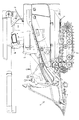
扱胴カバー10と前側板11との合せ部前方には、その合せ部の隙間から吹き出る吹出し物を前側下方の入口漏斗12上方まで案内する案内カバー13を設け、前側板に取り付けたカバー取付フレーム14に対し着脱自在に取り付けできる構成としている。案内カバー13は、側面視で扱胴9側が低くなるように上下方向に傾斜し,吹出し物を受け入れて入口漏斗12上へ案内落下させるべく構成している。また、この案内カバー13の下端には扱室内への穀稈供給作用によって弾性変位可能な弾性案内板15を連設している。剛性の高い鉄板などで構成された案内カバー13に対し、弾性案内板15は柔軟性のあるゴム材等で構成している。そして、この弾性案内板15は、案内カバーと同様に後方側ほど下方に傾斜すると共に、下端が前側板11より扱室内後位にまで延出されて該前側板11の下端面11bとの間に所定の間隙部Sを保持すべく構成してあり、弾性案内板が扱室内への穀稈供給作用によって上方に持ち上げられても前側板の下端面に接当してこれ以上の持ち上げが阻止されるようになっている。
A
案内カバー13のフィードチェン7側は、フィードチェン側ほど上方に高く切り上げた切上げ部13aを設けることによって入口漏斗12上を搬送される穀稈の株元部を層が厚くなっても引っ掛かりなくスムーズに扱室内へ導入することができる。また、案内カバー13にはフィードチェン7側を包囲する籾吹出し防止シール16を垂下している。更に、前記カバー取付フレーム14にも入口漏斗12の左右全幅にわたって籾飛散防止シール17を垂下させている。案内カバーが容易に着脱できるため、メンテナンスが容易であり、案内カバーと籾吹出し防止シールが同時に外れるため、整備時に邪魔にならない。また、案内カバー13には防塵カバーの後端を支持するための防塵カバー受け枠19が設けられている。従って、案内カバーを外すと防塵カバー受け枠も同時に外れるようになるため整備時に邪魔になることがない。
The
入口漏斗12の穂先側を前側板11の穀稈通路開口部と同一形状で構成することにより、入口漏斗上を搬送される穀稈の穂先部を引っ掛かり無くスムーズに扱室内へ導入することができる。
By configuring the tip side of the
入口漏斗12の前端部から下方に向けて防風カバー20を垂下させている。この防風カバー20によってエンジンのラジエータフアンの排風で入口漏斗下側に向けて風が流れ、ハカマなどがフレーム上に堆積するのを防止するようにしている。
The windproof cover 20 is suspended downward from the front end of the
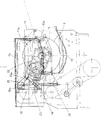
案内カバー13の内部には、図2に示すように、扱胴駆動用ギヤボック22及び排ワラ駆動ベルト23を配置している。また、該カバー13内には,扱胴駆動ベルト24及び排ワラ駆動ベルト23の両テンションスプリング25,26のテンション力調整部25a,26aを設けてあると共に、運転席5側に配置した構成としている。これによれば、案内カバーをオープンして容易にテンション調整が可能となる。
Inside the
更に、図2に示すように、前面視において、前側板11の反フィードチェン側に排ワラ搬送チェン31を駆動する排ワラ駆動軸30を配設し、該排ワラ駆動軸30は、扱胴9を軸架する前側板11、中側板及び後側板32を貫通して軸受け保持させた構成としている。
Further, as shown in FIG. 2, when viewed from the front, an exhaust
排ワラ駆動軸30から排ワラ搬送チェンへの駆動系は、図6に示すように、ベベルギヤケース34内のベベルギヤ機構34a、ベベルギヤケースより斜め後方に延出する排ワラ伝動軸36及び排ワラ搬送チェン31の中間部に設けた排ワラ駆動スプロケット37を介して排ワラ搬送チェン31を回転駆動すべく連動連結している。
As shown in FIG. 6, the drive system from the exhaust
前記後側板32には排ワラ伝動機構を回動自在に枢支する軸受部材33を設け、この軸受部材33の後方に排ワラベベルギヤケース34を設けている。ベベルギヤケース34は、前記軸受部材33に対し排ワラ駆動軸30の軸芯回りに回動自在に軸受保持させている。排ワラ駆動軸30の後方延長線上に支持させて設けた支軸38から後部排ワラ支持アーム39を突設し、前部排ワラ支持アーム35は中間支持部材35aを介して排ワラ搬送フレーム40に連結保持させ、後部排ワラ支持アーム39は支持部材39aを介して排ワラ搬送フレーム40の中間近くに連結保持させてあり、前部排ワラ支持ア−ム35がベベルギヤケース34と一体となって前記排ワラ駆動軸30の軸芯回りに上下回動し、後部 排ワラ支持アーム39が支軸38回りに上下回動する構成としている。
そして、前記排ワラ伝動軸36の外側を覆うパイプ41は、塩ビパイプで構成することにより、藁の巻き付き防止と軽量化を図るようにしている。また、塩ビパイプ41の外周はベベルギヤケース34側支持プレート42aと搬送フレーム40側支持プレート42bとによって支持する構成とし、左右方向の抜け止めはベベルギヤケース34と駆動スプロケット37によって行う構成としている。
The
And the
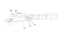
扱室後側板32と排ワラ搬送フレーム40とグレンタンクG側を連結する連結フレーム43は、伝動軸36を覆うパイプ41の下側を通すように該フレーム42自体を折り曲げた構成(図7参照)としている。これにより、排ワラの巻き付き防止と搬送通路の確保が図れる。
The
図8及び図9に示すように、エンジンよりカウンタ軸45に入力して扱胴9軸9a及び処理胴軸46にベルト47で入力するコンバインにおいて、脱穀前板48に補強部材49を設け、補強部材49は、扱胴9への入力ギヤケース50とカウンタ軸受部材51とに連結保持させると共に、支持部材52を介して刈取部の刈取懸架台53に連結保持させることで高負荷時の破損が防止できるように構成している。また、この補強部材49にはテンションプーリ54の軸支部55と入力ギヤケース50への取付部56を設けた構成としている。テンションアーム57が過剰にテンション力を与えないように該アームと一体回動する係止アーム58をカウンタ軸受部材51に係止保持させることで、カウンタ軸受部材51がスットッパーの役目を果たすように構成している。これによって高負荷時の破損が防止できる。
As shown in FIGS. 8 and 9, in the combine that is input from the engine to the
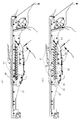
次に揺動選別棚Yの構成例について説明する。図10の(イ)及び(ロ)に示すように、前方側に固定チャフシーブ60を、後方側には連結プレート62の押し引き操作によって同時に揺動開閉する可動チャフシーブ61を設けた揺動棚構成において、固定チャフシーブ60、可動チャフシーブ61共に略等間隔に設け、固定チャフシーブ60の傾斜角度は、可動チャフシーブの全閉と全開の角度の間の範囲内角度に設定する。可動チャフシーブ61は、複数枚の帯板状のシーブ板63を等間隔に配置して上部を枢着(枢軸64)し、下部が左右の揺動棚側板67に設けた円弧状の長孔65に沿って揺動開閉するようにして相互の選別間隔の開度調節ができる構成としている。そして、可動チャフシーブを揺動開閉する連結プレート62の前端部には、最前部に位置するシーブ板63fのみ閉じ方向の動きを規制する長穴66を設けた構成としている。これにより、最前部のシーブ板63fが全閉時に固定チャフシーブと接触して隙間がなくなり籾の漏れが悪くなる問題点を解消することができる。
Next, a configuration example of the swing sorting shelf Y will be described. As shown in FIGS. 10A and 10B, the swing shelf structure is provided with a fixed
なお、可動チャフシーブは、固定チャフシーブより長くすることによって固定シーブと可動シーブを等間隔に設けることができる。
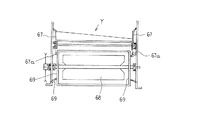
図11及び図12に示すように、貫流ファン68を揺動選別棚Yの下方に配置した唐箕において、ファン側板69を揺動棚側板67より内側に配置し、ファン側板69の吸引開口部70を機体側板71から延出したベルマウス72によって連通構成している。機体側板に吸引風を導入するベルマウスを設けることで、吸引風に乱れがなくなり、ファン効率が向上する。また、揺動棚の前方側板67aは、これがファン側板69と側面視で重なるように揺動選別棚より下方に延出させた構成としている。この構成により、揺動棚前方側板にくびれを形成する必要がなく、これ自体の強度アップを図ることができる。
Note that the fixed sheave and the movable sheave can be provided at equal intervals by making the movable chaff sheave longer than the fixed chaff sheave.
As shown in FIGS. 11 and 12, the
8 扱室
10 扱胴カバー
11 前側板
12 入口漏斗
13 案内カバー
15 弾性案内板
8 treatment room
10
Claims (2)
Priority Applications (1)
| Application Number | Priority Date | Filing Date | Title |
|---|---|---|---|
| JP2007172368A JP2009005662A (en) | 2007-06-29 | 2007-06-29 | Thresher |
Applications Claiming Priority (1)
| Application Number | Priority Date | Filing Date | Title |
|---|---|---|---|
| JP2007172368A JP2009005662A (en) | 2007-06-29 | 2007-06-29 | Thresher |
Publications (1)
| Publication Number | Publication Date |
|---|---|
| JP2009005662A true JP2009005662A (en) | 2009-01-15 |
Family
ID=40321422
Family Applications (1)
| Application Number | Title | Priority Date | Filing Date |
|---|---|---|---|
| JP2007172368A Pending JP2009005662A (en) | 2007-06-29 | 2007-06-29 | Thresher |
Country Status (1)
| Country | Link |
|---|---|
| JP (1) | JP2009005662A (en) |
-
2007
- 2007-06-29 JP JP2007172368A patent/JP2009005662A/en active Pending
Similar Documents
| Publication | Publication Date | Title |
|---|---|---|
| JP5840012B2 (en) | Combine | |
| CN101133696B (en) | Threshing device | |
| JP2905151B2 (en) | Threshing section cover of combine | |
| JPH0622630A (en) | Threshing equipment | |
| JP5724252B2 (en) | Thresher | |
| JPH05308843A (en) | Threshing and culm discharging device for combine | |
| JP3509189B2 (en) | Threshing equipment | |
| JPH11127677A (en) | Combine feed chain transmission | |
| JP2008136360A (en) | Threshing device | |
| JP2009039024A (en) | Combine dust remover | |
| JP3297823B2 (en) | Combine | |
| JP2007228943A (en) | Combine with roll baler | |
| KR20180071953A (en) | Rice straw treatment apparatus and rice straw cutting apparatus | |
| JP2000139190A (en) | Sorting unit structure of threshing equipment | |
| JP2905149B2 (en) | Threshing section cover of combine | |
| JP3822835B2 (en) | Threshing machine second processing equipment | |
| JP6824021B2 (en) | Threshing machine waste straw processing device | |
| JP3826953B2 (en) | Threshing device | |
| JP4051270B2 (en) | Combine threshing equipment | |
| JP3491290B2 (en) | Grain stalk transport clamping and feeding device in the combine threshing device | |
| JP2972085B2 (en) | Combine | |
| JP6692286B2 (en) | Exhaust straw cutting device | |
| JP6647795B2 (en) | Threshing equipment | |
| JP4499954B2 (en) | Combine | |
| JP2009268398A (en) | Stretching structure of threshing feed chain |