JP2009007733A - Cutting needle with replaceable knife - Google Patents
Cutting needle with replaceable knife Download PDFInfo
- Publication number
- JP2009007733A JP2009007733A JP2008165807A JP2008165807A JP2009007733A JP 2009007733 A JP2009007733 A JP 2009007733A JP 2008165807 A JP2008165807 A JP 2008165807A JP 2008165807 A JP2008165807 A JP 2008165807A JP 2009007733 A JP2009007733 A JP 2009007733A
- Authority
- JP
- Japan
- Prior art keywords
- knife
- needle
- cutting
- slit
- cutting needle
- Prior art date
- Legal status (The legal status is an assumption and is not a legal conclusion. Google has not performed a legal analysis and makes no representation as to the accuracy of the status listed.)
- Granted
Links
Images



Classifications
-
- D—TEXTILES; PAPER
- D04—BRAIDING; LACE-MAKING; KNITTING; TRIMMINGS; NON-WOVEN FABRICS
- D04B—KNITTING
- D04B15/00—Details of, or auxiliary devices incorporated in, weft knitting machines, restricted to machines of this kind
- D04B15/38—Devices for supplying, feeding, or guiding threads to needles
- D04B15/54—Thread guides
- D04B15/58—Thread guides for circular knitting machines; Thread-changing devices
- D04B15/60—Thread guides for circular knitting machines; Thread-changing devices with thread-clamping or -severing devices
-
- D—TEXTILES; PAPER
- D04—BRAIDING; LACE-MAKING; KNITTING; TRIMMINGS; NON-WOVEN FABRICS
- D04B—KNITTING
- D04B35/00—Details of, or auxiliary devices incorporated in, knitting machines, not otherwise provided for
- D04B35/02—Knitting tools or instruments not provided for in group D04B15/00 or D04B27/00
-
- D—TEXTILES; PAPER
- D04—BRAIDING; LACE-MAKING; KNITTING; TRIMMINGS; NON-WOVEN FABRICS
- D04B—KNITTING
- D04B35/00—Details of, or auxiliary devices incorporated in, knitting machines, not otherwise provided for
- D04B35/34—Devices for cutting knitted fabrics
Landscapes
- Engineering & Computer Science (AREA)
- Textile Engineering (AREA)
- Knitting Machines (AREA)
Abstract
Description
本発明は、取替え可能なナイフを備える切断針に関する。 The present invention relates to a cutting needle comprising a replaceable knife.
切断針は、例えば切断されたフラシ天の製造のために、編み機において使用されており、そのような切断針は、一端にフックを備え、さらにその近傍にナイフ部を備える針基体を有する。ナイフ部は、縫い目を切り開くために配置された鋭く研かれた切断縁を有する。長期にわたる使用によってナイフ部が鈍くなると、編み物生地の品質が損なわれることになる。したがって、切断針の交換が必要である。 Cutting needles are used in knitting machines, for example for the production of cut plush, such cutting needles having a needle base with a hook at one end and a knife part in the vicinity thereof. The knife portion has a sharply sharpened cutting edge arranged to cut open the seam. If the knife portion becomes dull after long-term use, the quality of the knitted fabric will be impaired. Therefore, it is necessary to replace the cutting needle.
この点に鑑み、本発明の目的は、改良された切断針を提供することにある。 In view of this point, an object of the present invention is to provide an improved cutting needle.
この目的は、請求項1による切断針にて達成される。
This object is achieved with a cutting needle according to
本発明による切断針は、針基体、ならびに針基体へと着脱可能に接続されたナイフを有する。この特徴により、摩耗したナイフの交換および新しい鋭く研かれたナイフとの交換が可能になる。また、摩耗したナイフを切断針から取り出して、単独で研ぎ直すことが可能である。 The cutting needle according to the present invention has a needle base and a knife removably connected to the needle base. This feature allows for replacement of worn knives and new sharpened knives. It is also possible to remove the worn knife from the cutting needle and sharpen it alone.
ナイフの交換が必要とされるときに、切断針を編み機に残したままにすることが可能である。編み機のロックを開く必要がない。これは、切断針の切断縁が鈍くなったときの編み機のメンテナンスを大幅に容易にする。 When the knife needs to be changed, it is possible to leave the cutting needle in the knitting machine. There is no need to open the knitting machine lock. This greatly facilitates maintenance of the knitting machine when the cutting edge of the cutting needle becomes dull.
好ましくは、切断針は、ナイフを収容し支持するためのシートを有する。このシートを、例えば、針基体を貫いて延びるスリットを呈するように構成することができる。好ましくは、スリットが、針基体の長手方向において見たときにフックの近傍に配置される。ナイフが、スリットのフランク間に保持される。このナイフが、好ましくは極めて最小限の横方向の遊びにてスリットに据えられ、したがって精密に設置される。スリットは、好ましくは針基体の中心に配置される。スリットは、横方向においてストリップまたはスリットの壁によって画定される。スリットの壁は、針基体の一部分であり、好ましくは平行なフランクを有する。スリットの幅およびスリットの壁の断面は、ほぼ同じ寸法を有することができる。好ましくは、それぞれがスリットの領域における針の厚さの3分の1を占めている。しかしながら、用途の分野によって、厚さの比は変更可能である。例えば、厚い切断ナイフが使用される場合には、スリットの幅が、スリットの領域における針の厚さの3分の1より大きくてもよい。スリットの幅が、針の厚さの半分を占めてもよく、特別な場合にはさらに大きくてもよい。極めて微細な切断ナイフが使用される場合には、スリットの幅が極めて小さくてもよく、例えばスリットの領域における針の厚さのわずか20%を占めるだけでよく、あるいはさらに小さくてもよい。 Preferably, the cutting needle has a sheet for receiving and supporting the knife. The sheet can be configured, for example, to exhibit a slit that extends through the needle base. Preferably, the slit is disposed in the vicinity of the hook when viewed in the longitudinal direction of the needle base. A knife is held between the flank of the slits. The knife is preferably placed in the slit with very minimal lateral play and is therefore precisely installed. The slit is preferably arranged in the center of the needle base. The slit is defined in the transverse direction by the strip or the wall of the slit. The wall of the slit is part of the needle base and preferably has parallel flank. The width of the slit and the cross section of the wall of the slit can have approximately the same dimensions. Preferably, each occupies one third of the needle thickness in the area of the slit. However, the thickness ratio can be changed depending on the field of application. For example, if a thick cutting knife is used, the width of the slit may be greater than one third of the thickness of the needle in the area of the slit. The width of the slit may occupy half the thickness of the needle and may be larger in special cases. If very fine cutting knives are used, the slit width may be very small, for example it may occupy only 20% of the needle thickness in the area of the slit, or even smaller.
スリットによって形成されるナイフ取り付け部は、好ましくは、ナイフを支持するための少なくとも1つのポジティブロック式(positive−locking)の保持手段を備える。このポジティブロック式の保持手段は、ナイフの少なくとも一方の端部または端部に近い領域において、ナイフを支持するためにナイフと係合する。例えば、ポジティブロック式の保持手段は、スリットへと延びる第1の突起であり、この突起が、ナイフの凹部に収容される。凹部は、ナイフの平たい両面で終端し、すなわちナイフを横切る開口の形状であってもよく、あるいは凹部を、フックに面するナイフの前端に設けてもよい。これらのポジティブロック式の手段が、ナイフの前方のフック側の端部を支持する枢動ヒンジを形成してもよい。 The knife attachment formed by the slit preferably comprises at least one positive-locking holding means for supporting the knife. This positive locking retaining means engages the knife to support the knife in at least one end or near the end of the knife. For example, the positive lock type holding means is a first protrusion extending into the slit, and this protrusion is accommodated in the recess of the knife. The recess may terminate on both flat sides of the knife, i.e. in the form of an opening across the knife, or the recess may be provided at the front end of the knife facing the hook. These positive locking means may form a pivoting hinge that supports the hook side end in front of the knife.
さらに、ナイフのためのモーメント支持面を、針基体に設けることができる。この面を、好ましくは、ポジティブロック式の保持手段から離れるスリットの一端部に位置させることができる。この面が、糸によってナイフへと加えられる圧力を吸収し、この圧力に対抗するように構成され、このナイフが次第に鈍くなる。好ましくは、モーメント支持面は、針基体の長手方向に広がる好ましくは平坦な表面である。好ましくは、この面が、上述のヒンジ手段の枢動軸に対してほぼ径方向に向けられている。 Furthermore, a moment support surface for the knife can be provided on the needle base. This surface can preferably be located at one end of the slit away from the positive-locking holding means. This surface is configured to absorb and counteract the pressure applied to the knife by the thread, and the knife becomes increasingly dull. Preferably, the moment support surface is a preferably flat surface extending in the longitudinal direction of the needle base. Preferably, this surface is oriented substantially radially with respect to the pivot axis of the hinge means described above.
着脱可能な接続手段を、ナイフの針基体との着脱可能な接続を達成するために使用することができる。この接続手段は、ポジティブロック式の保持手段から離れた点に設けられる戻り止め装置であってもよい。戻り止め装置は、例えばナイフに形成されたスナップイン式(snap−in)の舌であってもよく、これによりこのスナップイン式の舌を、スリットに設けられた第2の突起にロックし接続することができる。スナップイン式の舌は、好ましくは、針基体の長手方向を横切る方向に向けられている。ポジティブロック式の保持手段によって定められる枢動軸を参照すると、スナップイン式の舌は、好ましくは円周方向に向けられている。さらに、スナップイン式の舌は、好ましくはナイフの一体部分である。これは、ナイフにスリット状の凹部を設けることによって達成でき、これら凹部の間に、ナイフの材料で構成される舌が行き止まる。好ましくは、この舌の自由端に、針基体に係合できる戻り止めのくぼみが設けられる。 Removable connection means can be used to achieve a removable connection with the needle base of the knife. The connecting means may be a detent device provided at a point away from the positive lock type holding means. The detent device may be, for example, a snap-in tongue formed on a knife, whereby the snap-in tongue is locked and connected to a second protrusion provided in the slit. can do. The snap-in tongue is preferably oriented in a direction transverse to the longitudinal direction of the needle base. Referring to the pivot axis defined by the positive-locking holding means, the snap-in tongue is preferably oriented circumferentially. Furthermore, the snap-in tongue is preferably an integral part of the knife. This can be achieved by providing slits in the knives with slit-like recesses, between which the tongue made of the material of the knife is dead. Preferably, the free end of the tongue is provided with a detent recess that can engage the needle base.
例えば戻り止め装置の形状である着脱可能な接続手段を、保持手段と同じ位置に設けることも可能であり、その場合には、接続手段が保持手段に相当する。戻り止め装置は、例えば隆起であってよく、そのような隆起が、ナイフの開口へと延び入り、ポジティブロック式の係合によってこのナイフを所定の位置に保持および固定する。隆起は、スリットの壁の材料で構成されるピンの形状を有することができる。切断ナイフの開口およびスリットの壁の隆起のサイズおよび寸法を、取り付け後の切断ナイフが針基体のスリットにおいて軸方向に固定されるように、互いに合わせて構成することができる。径方向の固定のために、同じまたは同様の形式の第2の戻り止め装置を、第1の戻り止め装置から離れた位置に設けることができる。好ましくは、これら2つの戻り止め手段の一方が、切断ナイフの前端領域に配置され、他方の保持または戻り止め手段が、切断ナイフの後端領域に配置される。切断ナイフの固定のために、切断ナイフの開口ごとに2つの隆起を設けることが可能である。それぞれの隆起が、スリットの壁から延びて、切断ナイフの開口へと突き出す。これら2つの隆起は、鏡像対称であってよく、互いに正対して位置することができる。切断ナイフを針基体の所定の位置に固定するために、開口が、隆起の形状とは異なる形状を有してもよい。例えば、開口を、長穴として構成することができる。このとき、スリットの2つの壁の隆起を、好ましくは、一方の隆起が長穴の後方領域へと突き出し、反対側の隆起が長穴の前方領域へと突き出すように、横方向にずらすことができる。隆起の高さは、極小限であってもよい。2つの隆起が1つの開口へと突き出す場合には、2つの隆起の高さの合計を、切断ナイフの幅または開口の長さよりも小さくすることができる。このように、好ましくは、1つの開口へと突き出す2つの隆起の間にすき間が存在する。隆起は、さまざまな形状を有することができ、例えば円柱形、球形、または他の湾曲した形状を有することができる。 For example, a detachable connecting means having the shape of a detent device can be provided at the same position as the holding means, in which case the connecting means corresponds to the holding means. The detent device can be, for example, a ridge that extends into the opening of the knife and holds and secures the knife in place by positive locking engagement. The ridge can have the shape of a pin composed of the material of the slit wall. The size and dimensions of the opening of the cutting knife and the ridges of the slit wall can be adapted to each other such that the attached cutting knife is axially fixed in the slit of the needle base. For radial fixation, a second detent device of the same or similar type can be provided at a location remote from the first detent device. Preferably one of these two detent means is arranged in the front end region of the cutting knife and the other holding or detent means is arranged in the rear end region of the cutting knife. For fixing the cutting knife, it is possible to provide two ridges for each opening of the cutting knife. Each ridge extends from the wall of the slit and projects into the opening of the cutting knife. These two ridges can be mirror image symmetric and can be located directly opposite each other. In order to secure the cutting knife in place on the needle base, the opening may have a shape different from the shape of the ridge. For example, the opening can be configured as a long hole. At this time, the ridges of the two walls of the slit are preferably shifted laterally so that one ridge protrudes into the rear region of the slot and the opposite ridge protrudes into the front region of the slot. it can. The height of the ridge may be a minimum limit. If two ridges protrude into one opening, the sum of the heights of the two ridges can be less than the width of the cutting knife or the length of the opening. Thus, there is preferably a gap between two ridges that project into one opening. The ridges can have a variety of shapes, for example, cylindrical, spherical, or other curved shapes.
切断針の好ましい実施形態を参照すると、ナイフと針基体との間に作用する軸方向ロック装置が設けられる。この軸方向ロック装置は、動作時にナイフに作用する軸方向の力が特に、ナイフの戻り止め装置に作用することを防止し、動作時にナイフが針基体において軸方向に動かないことを保証するように配置されている。軸方向ロック装置は、ナイフと針基体との間で有効なポジティブロック式の相互作用手段を代表することができる。好ましくは、軸方向ロック装置は、ナイフのための少なくとも1つの当接面を有し、この当接面が、ロック装置へと向かうナイフの軸方向の移動に対抗する。これは、例えば、針基体に設けられた軸方向ロック装置の当接面が、好ましくはポジティブロック式の保持手段に向かって面することを意味する。このような当接面を、例えば、スリット内に設けられ、戻り止め装置とポジティブロック式の保持手段との間に位置するストリップに設けることができる。あるいは、例えばナイフの端面に作用するように軸方向ロック装置を設けることができる。 Referring to the preferred embodiment of the cutting needle, an axial locking device is provided that acts between the knife and the needle base. This axial locking device prevents the axial force acting on the knife during operation, in particular from acting on the detent device of the knife, so as to ensure that the knife does not move axially in the needle base during operation. Is arranged. The axial locking device can represent a positive locking interaction means effective between the knife and the needle base. Preferably, the axial locking device has at least one abutment surface for the knife, which abuts against the axial movement of the knife towards the locking device. This means, for example, that the contact surface of the axial locking device provided on the needle base preferably faces towards the positive locking holding means. Such an abutment surface can be provided, for example, in a strip provided in the slit and located between the detent device and the positive locking holding means. Alternatively, an axial locking device can be provided to act on the end face of the knife, for example.
ナイフを針基体に支持する接続手段の特定の構成にかかわらず、本発明によれば、摩耗したナイフの簡単かつ迅速な交換が可能になり、したがって編み機のメンテナンスが大いに迅速化される。さらに、本発明によれば、ナイフおよび針基体を、個々の目的に照らして最適化された異なる製造技術の実現によって、それぞれの使用目的に合わせて最適に設計された異なる材料で、別個に製造することができる。また、針基体およびナイフを、さまざまな数にて別個に供給することができ、したがっていくつかのナイフを、針基体に順次に設置して摩耗するまで使用することができる。 Regardless of the specific configuration of the connecting means for supporting the knife to the needle base, the present invention allows for a simple and quick replacement of the worn knife, thus greatly speeding up the maintenance of the knitting machine. Furthermore, according to the present invention, the knife and needle substrate are manufactured separately, with different materials optimized for their intended use, by the realization of different manufacturing techniques optimized for the individual purpose. can do. Also, the needle base and knives can be supplied separately in various numbers, so that several knives can be sequentially installed on the needle base and used until worn.
本発明の好都合な実施形態のさらなる詳細が、明細書、図面および特許請求の範囲からもたらされる。明細書は、本発明の基本的な態様およびさまざまな状況に限定されている。図面がさらなる詳細を示しており、当業者であれば、図面を、明細書を補うものとして通常の方法で利用することができる。 Further details of advantageous embodiments of the invention result from the description, the drawings and the claims. The specification is limited to the basic aspects of the invention and various situations. The drawings show further details, and those skilled in the art can utilize the drawings in a conventional manner as a supplement to the specification.
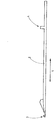
図1は、細長い基体2を有する切断針1を示しており、基体2の端部にフック3が設けられる。基体2は、駆動装置に接続するように配置されている。これを達成するために、図2によって示されているとおり、フック3から離れた位置において、基体に足4が設けられる。この足が、編み機の針ロック部と相互作用するように配置されており、その結果として針基体2が、例えばダイアルまたは編みシリンダなどの針床の針チャネルにおいて軸方向に、すなわち軸の長手方向Lに移動する。例えば矩形の断面を有する針基体2が、図1に示されているように、フック3の近傍にスリット5を有し、これによりナイフ6がこのスリットに保持されている。このようにするうえで、スリット5は、好ましくは、スロート領域7においてフック3の直近からスタートし、針の胸部8を超えて延びている。このスリットは、真っすぐであって、2つのスリットフランクによって画定されている。図3によって示されているように、スリット3は、このようにするうえで、針の上面9から針の背面10へと延びており、すなわち貫通を形成している。したがって、スリット5は、針の上面9ならびに針の背面10に向かって開いている。しかしながら、スリット5が、必要であるならば針の背面10に向かって閉じていてもよいことに、注意すべきである。
FIG. 1 shows a cutting
スリット5は、ナイフ6を支持および固定するために使用され、ナイフ6は、かみそりの刃のような平面状の平坦かつ小さなブレードとして構成することができる。すなわち、このナイフは、お互いから離れる方向に向いた2つの平坦な面を有し、これらの平坦面が、大きな遊びを持つことなくスリットのフランク間に保持されている。このナイフは、スロート7から離れて上昇する縁部において研かれ、これにより、図示のとおり、真っ直ぐな、あるいは、任意の異なる形状を有する切断縁11が形成されている。この切断縁が、好ましくは、軸の長手方向Lに対して鋭角で延びている。
The
切断針1のナイフ6および針基体2は、好ましくは別個に製造され、その後に互いに接続される。したがって、ナイフ6および針基体2を、例えば種類の異なる鋼など、異なる材料で構成することができる。例えば、ナイフ6の材料が、意図される使用状況において切断縁11の摩耗が最小限となるような範囲で、最適化される。これに対して、針基体2の材料を、靱性または他の特性に関して最適化することができる。さらに、ナイフ6ならびに針基体2に、最適化された異なる種類の摩耗低減コーティングを設けることが可能である。
The
好ましくは、少なくとも1つの有効なポジティブロック式の保持手段12が、針基体2とナイフ6との間に存在し、この保持手段は、例えばスリット5のフック側の端部13に配置される。保持手段12は、例えば、スリット5の端部13にあらかじめ形成された第1の突起14で構成され、この突起が、ナイフ6の関連端部に設けられた切り欠き15に組み合わせられる。第1の突起14を、円弧を形成するスリット5のそれぞれの端面の間に設けることができる。図3および4の比較によって示されるとおり、ポジティブロック式の保持手段12が、図4および5の投影面に垂直なヒンジ軸を定める一種のヒンジを形成しており、このヒンジ軸は、基体の長手方向Lを横切る方向に向けられている。この結果として、ナイフ6を、図4に一点鎖線の円弧16によって示されているように、回転させてスリット5へと出し入れすることができる。
Preferably, at least one effective positive-locking holding means 12 is present between the
保持手段12から離れる位置において、針基体2は、好ましくは平坦なモーメント支持面17を有し、モーメント支持面17は、適切に成形されたナイフ6の支持面18のための支持面として作用し、この支持面も、本発明の例示的な実施形態においては平坦な支持面である。モーメント支持面17は、保持手段12の回転の中心に対してほぼ径方向に向けられており、すなわち円弧16を横切る方向に向けられている。この表面が、糸の切断の際に生じる力が切断縁11に作用し、この力によって、ナイフ6をポジティブロック式の保持手段12の仮想のヒンジ軸を中心としてモーメント支持面17に対して円弧16の方向に押すトルクが生じるときに、ナイフ6を支持する。
At a position away from the holding means 12, the
ナイフ6を図3による作業位置に固定するために、締め付け手段が設けられ、この手段は、本発明の場合には、戻り止め装置19によって代表されている。戻り止め装置19は、固定係合へと動かすことができる2つの部材を備え、それら部材の一方が、針の軸2に設けられ、他方が、ナイフ6に設けられる。例示的な実施形態を参照すると、これらの部材が、針の軸2側においては、スリット5のフック3から離れる端部21に設けられた第2の突起20によって形成されている。ナイフ6側においては、戻り止め部材が、ナイフ6と一体の構成要素である舌22によって代表されている。この例示的な実施形態においては、第2の突起20は、アーチ形に湾曲した2つの表面によって画定されている。この第2の突起は、フック3の方向に延びる先端を形成している。
In order to fix the
舌22は、ナイフ6の材料で構成されている。この舌は、2つのスリット23、24によって解放されており、すなわちナイフ6の平坦な基体から切り出され、ナイフ6が解放された細長い部位を形成している。この舌は、一端において継ぎ目および変わり目なしでナイフ6の残りの材料へとつながっている。他端を、切り欠き15に対して接離するように弾性的に動かすことができる。さらに、この弾性的に動かすことができる他端に、凹部または切り欠き25が、支持面18がモーメント支持面17に当接するときに第2の突起20の先端を受け入れることができるように設けられる。
The
さらに、切断針1は、基体2に設けられた対向支持部27およびナイフ6に設けられた当接面28に関連する軸方向ロック装置26を有することができる。対向支持部27を、スリット5を横切るストリップとして構成でき、このストリップが、スリット5を画定している2つの顎部(jaw)に一体に接続されている。ストリップまたは対向支持部27が、好ましくは、フック3へと向けられた小面(facet)29を有する。この小面が、保持手段12またはフック3から離れるように向けられた当接面28に組み合わせられる。当接面28は、切断縁11とは反対側の縁においてナイフ6に設けられた口状の開口29’’の境界壁の一部であってよい。
Furthermore, the cutting
切断針1は、以下のように機能する。
The cutting
動作時、切断針1は、軸の長手方向Lに沿って往復運動する。そのようにする際、フック3が糸を捕まえ、縫い目の半分または縫い目を形付ける。縫い目がナイフ6に向かって押され、あるいは切断針1が、ナイフ6の切断縁11が縫い目を通過して移動するほど充分に遠く繰り出されると、縫い目が切り開かれる。他の力に加え、フック3から離れる方向に向いた力が、ナイフ6へと加わる。この力が、当接面28を対向支持部27に対して押し付ける。結果として、力が戻り止め装置19に加わらないように維持される。ナイフ6が、針基体2にしっかりと保持される。
In operation, the cutting
ナイフは、以下のように交換される。 The knife is changed as follows.
ナイフ6が、スリット5から引き出され、図4によって示されているとおりに回転させられる。その際に、舌22が、弾性的に撓んで、第2の突起20から滑り出る。さらに、ナイフ6が、対向支持部27から離れるように回転させられ、したがってこのナイフをスリット5、すなわち図4に示した位置から、完全に引き出すことができる。新たなナイフ6は、最初にこのナイフのフック側の端部をスリット5へと挿入させ、これによりこのナイフの切り欠き15を第1の突起14に位置させることで、挿入される。次いで、ナイフ6は、円弧16に沿ってスリットへと回転させられ、これにより舌22の切り欠き25が第2の突起20に係合し、支持面18がモーメント支持面17に対して当接する。この作業は、切断針1を針床から取り外すことなく実行可能である。
The
図5は、軸方向ロック装置26が上述のようにスリットの両端13、21の間に配置されるのではなく、フック3の透視図から見てナイフ6の後方に配置される一変形の実施形態を示している。この実施形態は、例えば比較的高い軸を有し、すなわち針の上面9と針の背面10との距離が比較的大きい切断針1’に適している。対向支持部27’を、スリットの延長部5’の内部に設けることができ、この対向支持部が、ナイフ6の端面31と相互に作用する。したがって、端面31が、当接面28に対応する当接面を形成する。対向支持部27’は、針基体2を横方向に通過する対応する開口に設置されるピンであってよい。しかしながら、ピンが、互いに重なるようにスリットの延長部5’のフランクから突き出す突起によって代表されてもよい。そのようなハーフピン(half−pin)は、ラッチ式の針の舌支持部の製造と同様にして製造することができる。
FIG. 5 shows an implementation of a variant in which the
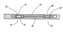
図6は、図1による切断針1の一変形の実施形態を示している。この切断針は、軸方向ロック装置26’、保持手段12’、および上述の手段とは異なる戻り止め装置19’を備える。これら以外については、上述と同じ参照番号が使用されている。好ましくは、少なくとも1つのポジティブロック式の保持手段12’が、針基体2とナイフ6との間で動作可能であり、この保持手段が、例えば、スリット5のフック側の端部13に位置するナイフ6の端部領域に配置される。保持手段12’は、例えば、針基体2の長手方向Lに向かって横方向に延びる開口の形状を有する切り欠き15’によって代表されている。スリットの壁34から延びる第1の突起14’およびスリットの壁35から延びる第1の突起14’’が、長穴の形状を有するこの開口15’へと突き出している(図7)。長穴15’は、フック3の方向においては端部33によって画定され、反対側においては、端部32によって画定されている。第1の突起14’および14’’を、スリットの壁34、35の材料で構成することができる。第1の突起14’および14’’を、軸方向においてお互いから離して位置させることができる。図7による例示的な実施形態を参照すると、第1の突起14’が、開口15’の端部33と相互作用し、第1の突起14’’が、開口15’の端部32と相互作用し、したがって端部32および33とのポジティブロックを形成している。第1の突起14’および14’’の表面は、球形部の形状を有することができ、球面の一部分を備えることができる。第1の突起14’、14’’の高さは、最小限であってよく、これによりナイフ6の開口15’へと最小限に延びるだけでよい。ナイフをスリット5へとはめ込むことができるようにするために、第1の突起14’、4’’の高さおよび位置決めは、スリットの壁34、35の可撓性と関係なく独立に定められる。スリットの壁34、35の大きい可撓性により、第1の突起14’、4’’の大きい高さと、ナイフ6の端部の近くの領域における位置決めが可能になる。スリットの壁34、35が変形しにくいとき、第1の突起14’、14’’の高さが最小限である必要があり、可能な限りナイフ6の長手方向延長部の中央付近におけて位置決める必要がある。
FIG. 6 shows an embodiment of a variant of the cutting
図6による例示的な実施形態の戻り止め装置19’は、保持手段12’から離れた位置に配置される。この装置は、基本的には、保持手段12’と同じ構成を有する。この装置は、ナイフの長手方向を横切る方向にナイフ6を通過する穴状の切り欠き25'を有する。スリットの壁34から延びる第2の突起20’’およびスリットの壁35から延びる突起20’が、この開口25’へと突き出している。両方の突起20’および20’’は、軸方向において同じ位置にあり、互いに対向して、開口25’とのポジティブロックを形成している。第2の突起20’および20’’の高さおよび位置に関しては、第1の突起14’および14’’に関して上述した基準が同様に当てはまる。
The detent device 19 'of the exemplary embodiment according to Fig. 6 is arranged at a position remote from the holding means 12'. This device basically has the same configuration as the holding means 12 '. This device has a hole-like notch 25 'that passes through the
さらに、図6による切断針1は、基体2上の対向支持部27’とナイフ6上の当接面28’とを備える軸方向ロック装置26’を有することができる。対向支持部27’は、スリット5を画定している面または縁であってよい。この縁または対向支持部27’が、好ましくは、フック3へと向けられた小面29’を有する。この小面が、保持手段12’またはフック3から離れる方向を向いた当接面28’に組み合わせられる。
Furthermore, the cutting
図6および図7による本発明の切断針1のナイフ6は、例えば平頭プライヤ(図示せず)などの手段を使用し、ナイフ6の平らな面を把持し、針の上面9の方向へと上方に引っ張ることで交換される。その際に、スリットの壁34、35が弾性的に撓み、これにより突起14’、14’’および20’、20’’が開口15’および25’から解放され、ナイフ6を取り去ることができる。新たなナイフ6を、補助的な手段を使用して針の上面9から針の背面10の方向に挿入することで、空いたスリット5に挿入することができ、これにより突起14’、14’’、20’、20’’が開口15’および25’とスナップ閉鎖を形成する。
The
以上のようにして、編み機および類似の用途のための切断針1が提供され、この切断針は、ナイフ6を好ましくは戻り止め装置19、19’によって着脱可能に保持する針基体2を有する。このような切断針1は、編み機のメンテナンスのコストを低減するとともに、針基体2およびナイフ6を製造技術および材料を考慮して最適化するための方法を開示している。
As described above, a cutting
Claims (10)
前記針基体(2)へと着脱可能に接続されるナイフ(6)と、を備える、
編み機用の切断針(1)。 A needle base (2) provided with a hook (3) at one end;
A knife (6) detachably connected to the needle base (2),
Cutting needle for knitting machines (1).
Applications Claiming Priority (2)
| Application Number | Priority Date | Filing Date | Title |
|---|---|---|---|
| EP07012443.3 | 2007-06-26 | ||
| EP07012443.3A EP2009160B1 (en) | 2007-06-26 | 2007-06-26 | Cutting needle with replaceable blade |
Publications (2)
| Publication Number | Publication Date |
|---|---|
| JP2009007733A true JP2009007733A (en) | 2009-01-15 |
| JP5116579B2 JP5116579B2 (en) | 2013-01-09 |
Family
ID=39530161
Family Applications (1)
| Application Number | Title | Priority Date | Filing Date |
|---|---|---|---|
| JP2008165807A Expired - Fee Related JP5116579B2 (en) | 2007-06-26 | 2008-06-25 | Cutting needle with replaceable knife |
Country Status (5)
| Country | Link |
|---|---|
| US (1) | US7533547B2 (en) |
| EP (1) | EP2009160B1 (en) |
| JP (1) | JP5116579B2 (en) |
| KR (1) | KR101036758B1 (en) |
| CN (1) | CN101333728B (en) |
Families Citing this family (5)
| Publication number | Priority date | Publication date | Assignee | Title |
|---|---|---|---|---|
| NL8302089A (en) | 1983-06-13 | 1985-01-02 | Doornes Transmissie Bv | INFLATABLE VARIABLE TRANSMISSION. |
| US9900609B2 (en) * | 2013-01-04 | 2018-02-20 | Nokia Technologies Oy | Apparatus, a method and a computer program for video coding and decoding |
| CN204825367U (en) * | 2015-06-04 | 2015-12-02 | 连云港元丰机械制造有限公司 | Sword hook assembly suitable for cut a ring machine |
| CN110042547B (en) * | 2019-04-22 | 2021-02-26 | 福建睿能科技股份有限公司 | Flat knitting machine and crochet hook thereof |
| EP4703504A1 (en) * | 2024-08-26 | 2026-03-04 | Groz-Beckert KG | Multi-part element for textile machines and method for producing the textile machine element |
Citations (2)
| Publication number | Priority date | Publication date | Assignee | Title |
|---|---|---|---|---|
| DE10227533C1 (en) * | 2002-06-20 | 2003-12-11 | Groz Beckert Kg | Stitch transfer needle, for a knitter, has the mounting section of the stitch transfer spring securely bonded in place within a slit, which opens at one of the narrow sides of the needle body |
| JP2006291442A (en) * | 2005-04-06 | 2006-10-26 | Groz Beckert Kg | Cutting needle |
Family Cites Families (10)
| Publication number | Priority date | Publication date | Assignee | Title |
|---|---|---|---|---|
| US1120989A (en) * | 1913-06-19 | 1914-12-15 | Louis N D Williams | Knitting-machine needle. |
| US2335075A (en) * | 1941-04-04 | 1943-11-23 | Needham William | Knitting machine |
| US3040551A (en) * | 1956-02-10 | 1962-06-26 | George A Urlaub | Stretch fabric and method |
| DE2126522A1 (en) | 1971-05-28 | 1972-12-14 | Preda. Adolf Georg, 7863 Fahrnau | Raschel knitting - single bed machine for plain and patterned plush |
| US4026126A (en) * | 1974-12-07 | 1977-05-31 | Otto Nuber | Method of knitting knit plush fabric having a nap, or pile loops |
| US4089192A (en) * | 1976-04-30 | 1978-05-16 | Kohorn Alfred O | Knitting machine needles with improved cut-off and spring location |
| US4537048A (en) * | 1980-12-08 | 1985-08-27 | Monarch Knitting Machinery Corp. | Pile loop forming and cutting elements for circular knitting machines |
| DE19905668C2 (en) * | 1999-02-11 | 2001-01-25 | Groz Beckert Kg | Lanyard for transferring stitches |
| IT1307796B1 (en) * | 1999-09-14 | 2001-11-19 | Pinzauti Lucia | DEVICE AND PROCEDURE FOR THE CONSTRUCTION OF KNITTED FABRICS WITH THE FORMATION OF HAIR CUT ON A REVERSE KNIT, WHOSE RANGES OF |
| KR20030084297A (en) * | 2002-04-26 | 2003-11-01 | 채병각 | A knitting method and an apparatus of high long pile fabrics |
-
2007
- 2007-06-26 EP EP07012443.3A patent/EP2009160B1/en active Active
-
2008
- 2008-06-24 KR KR1020080059469A patent/KR101036758B1/en not_active Expired - Fee Related
- 2008-06-25 JP JP2008165807A patent/JP5116579B2/en not_active Expired - Fee Related
- 2008-06-26 US US12/146,970 patent/US7533547B2/en active Active
- 2008-06-26 CN CN2008101293273A patent/CN101333728B/en active Active
Patent Citations (2)
| Publication number | Priority date | Publication date | Assignee | Title |
|---|---|---|---|---|
| DE10227533C1 (en) * | 2002-06-20 | 2003-12-11 | Groz Beckert Kg | Stitch transfer needle, for a knitter, has the mounting section of the stitch transfer spring securely bonded in place within a slit, which opens at one of the narrow sides of the needle body |
| JP2006291442A (en) * | 2005-04-06 | 2006-10-26 | Groz Beckert Kg | Cutting needle |
Also Published As
| Publication number | Publication date |
|---|---|
| EP2009160A1 (en) | 2008-12-31 |
| US7533547B2 (en) | 2009-05-19 |
| JP5116579B2 (en) | 2013-01-09 |
| KR20080114548A (en) | 2008-12-31 |
| US20090000338A1 (en) | 2009-01-01 |
| KR101036758B1 (en) | 2011-05-25 |
| CN101333728A (en) | 2008-12-31 |
| CN101333728B (en) | 2011-06-08 |
| EP2009160B1 (en) | 2016-09-28 |
Similar Documents
| Publication | Publication Date | Title |
|---|---|---|
| JP5116579B2 (en) | Cutting needle with replaceable knife | |
| JP5440970B2 (en) | Tufting device gripper | |
| JP2009178400A (en) | Razor | |
| KR20170100570A (en) | A shaving blade cartridge and a shaver comprising such shaving blade cartridge | |
| GB2290560A (en) | A clip for a tufting machine hook | |
| US8485114B2 (en) | Needle plate and sewing machine | |
| KR20180117110A (en) | An insert clamping mechanism and a clamping tool of an interchangeable grooving tool | |
| CN106460265A (en) | Knitting tool for knitting machines | |
| US8302546B2 (en) | Tufting gripper with spring-biased support of an insert | |
| CN101008131A (en) | Knitting element, especially needle of warp-knitting machine | |
| JP2007197895A (en) | Knitting machine bar | |
| JP2009215693A (en) | Transfer needle with internal spring tip | |
| JP2012085957A (en) | Mechanism for attaching presser of sewing machine, and sewing machine | |
| KR20090020861A (en) | Rotary book device for high speed sewing machine | |
| KR20060107301A (en) | Cutting needle | |
| CN105755684B (en) | Sewing machine | |
| KR20110035957A (en) | Slider needle with built-in center strip | |
| JP2009068135A (en) | Flat knitting machine and latch needle | |
| JP2004277985A (en) | Hat holding device for embroidery machine | |
| JP3737722B2 (en) | Needle threader | |
| WO2006070763A1 (en) | Weft knitting machine with movable sinker | |
| TWI588312B (en) | Wire finger for wire changing device | |
| CN108085857A (en) | For the yarn guide and knitting machine of knitting machine | |
| JP3165560U (en) | Tablet cutting scissors | |
| JP3184315U (en) | Reciprocating cutting tool |
Legal Events
| Date | Code | Title | Description |
|---|---|---|---|
| A131 | Notification of reasons for refusal |
Free format text: JAPANESE INTERMEDIATE CODE: A131 Effective date: 20110208 |
|
| A521 | Request for written amendment filed |
Free format text: JAPANESE INTERMEDIATE CODE: A523 Effective date: 20110502 |
|
| A131 | Notification of reasons for refusal |
Free format text: JAPANESE INTERMEDIATE CODE: A131 Effective date: 20120110 |
|
| A521 | Request for written amendment filed |
Free format text: JAPANESE INTERMEDIATE CODE: A523 Effective date: 20120406 |
|
| TRDD | Decision of grant or rejection written | ||
| A01 | Written decision to grant a patent or to grant a registration (utility model) |
Free format text: JAPANESE INTERMEDIATE CODE: A01 Effective date: 20121009 |
|
| A01 | Written decision to grant a patent or to grant a registration (utility model) |
Free format text: JAPANESE INTERMEDIATE CODE: A01 |
|
| A61 | First payment of annual fees (during grant procedure) |
Free format text: JAPANESE INTERMEDIATE CODE: A61 Effective date: 20121016 |
|
| R150 | Certificate of patent or registration of utility model |
Free format text: JAPANESE INTERMEDIATE CODE: R150 Ref document number: 5116579 Country of ref document: JP |
|
| FPAY | Renewal fee payment (event date is renewal date of database) |
Free format text: PAYMENT UNTIL: 20151026 Year of fee payment: 3 |
|
| R250 | Receipt of annual fees |
Free format text: JAPANESE INTERMEDIATE CODE: R250 |
|
| R250 | Receipt of annual fees |
Free format text: JAPANESE INTERMEDIATE CODE: R250 |
|
| R250 | Receipt of annual fees |
Free format text: JAPANESE INTERMEDIATE CODE: R250 |
|
| R250 | Receipt of annual fees |
Free format text: JAPANESE INTERMEDIATE CODE: R250 |
|
| R250 | Receipt of annual fees |
Free format text: JAPANESE INTERMEDIATE CODE: R250 |
|
| R250 | Receipt of annual fees |
Free format text: JAPANESE INTERMEDIATE CODE: R250 |
|
| R250 | Receipt of annual fees |
Free format text: JAPANESE INTERMEDIATE CODE: R250 |
|
| R250 | Receipt of annual fees |
Free format text: JAPANESE INTERMEDIATE CODE: R250 |
|
| R250 | Receipt of annual fees |
Free format text: JAPANESE INTERMEDIATE CODE: R250 |
|
| LAPS | Cancellation because of no payment of annual fees |