JP2009007744A - Eaves - Google Patents
Eaves Download PDFInfo
- Publication number
- JP2009007744A JP2009007744A JP2007167363A JP2007167363A JP2009007744A JP 2009007744 A JP2009007744 A JP 2009007744A JP 2007167363 A JP2007167363 A JP 2007167363A JP 2007167363 A JP2007167363 A JP 2007167363A JP 2009007744 A JP2009007744 A JP 2009007744A
- Authority
- JP
- Japan
- Prior art keywords
- front plate
- eaves
- locking
- ear
- locking groove
- Prior art date
- Legal status (The legal status is an assumption and is not a legal conclusion. Google has not performed a legal analysis and makes no representation as to the accuracy of the status listed.)
- Pending
Links
- 229920005989 resin Polymers 0.000 claims abstract description 20
- 239000011347 resin Substances 0.000 claims abstract description 20
- 238000012856 packing Methods 0.000 abstract description 3
- 210000005069 ears Anatomy 0.000 description 4
- 239000000463 material Substances 0.000 description 4
- XEEYBQQBJWHFJM-UHFFFAOYSA-N Iron Chemical compound [Fe] XEEYBQQBJWHFJM-UHFFFAOYSA-N 0.000 description 2
- 229920002877 acrylic styrene acrylonitrile Polymers 0.000 description 2
- 239000003795 chemical substances by application Substances 0.000 description 2
- 229910052751 metal Inorganic materials 0.000 description 2
- 239000002184 metal Substances 0.000 description 2
- 229920003002 synthetic resin Polymers 0.000 description 2
- 239000000057 synthetic resin Substances 0.000 description 2
- 239000004925 Acrylic resin Substances 0.000 description 1
- 229920000178 Acrylic resin Polymers 0.000 description 1
- YAAQEISEHDUIFO-UHFFFAOYSA-N C=CC#N.OC(=O)C=CC=CC1=CC=CC=C1 Chemical compound C=CC#N.OC(=O)C=CC=CC1=CC=CC=C1 YAAQEISEHDUIFO-UHFFFAOYSA-N 0.000 description 1
- 229920000049 Carbon (fiber) Polymers 0.000 description 1
- 101100460844 Mus musculus Nr2f6 gene Proteins 0.000 description 1
- BZHJMEDXRYGGRV-UHFFFAOYSA-N Vinyl chloride Chemical compound ClC=C BZHJMEDXRYGGRV-UHFFFAOYSA-N 0.000 description 1
- 229910052782 aluminium Inorganic materials 0.000 description 1
- XAGFODPZIPBFFR-UHFFFAOYSA-N aluminium Chemical compound [Al] XAGFODPZIPBFFR-UHFFFAOYSA-N 0.000 description 1
- 239000004917 carbon fiber Substances 0.000 description 1
- 229920006026 co-polymeric resin Polymers 0.000 description 1
- 229920001577 copolymer Polymers 0.000 description 1
- 239000011162 core material Substances 0.000 description 1
- 230000000694 effects Effects 0.000 description 1
- 239000000945 filler Substances 0.000 description 1
- 239000003365 glass fiber Substances 0.000 description 1
- 229910052742 iron Inorganic materials 0.000 description 1
- VNWKTOKETHGBQD-UHFFFAOYSA-N methane Chemical compound C VNWKTOKETHGBQD-UHFFFAOYSA-N 0.000 description 1
- 125000002496 methyl group Chemical group [H]C([H])([H])* 0.000 description 1
- 230000000414 obstructive effect Effects 0.000 description 1
- 239000000123 paper Substances 0.000 description 1
- 229920003229 poly(methyl methacrylate) Polymers 0.000 description 1
- 229920005668 polycarbonate resin Polymers 0.000 description 1
- 239000004431 polycarbonate resin Substances 0.000 description 1
- -1 polyethylene terephthalate Polymers 0.000 description 1
- 229920000139 polyethylene terephthalate Polymers 0.000 description 1
- 239000005020 polyethylene terephthalate Substances 0.000 description 1
- 239000004926 polymethyl methacrylate Substances 0.000 description 1
- 229920005672 polyolefin resin Polymers 0.000 description 1
- 229920005990 polystyrene resin Polymers 0.000 description 1
- 229920005749 polyurethane resin Polymers 0.000 description 1
- 238000006748 scratching Methods 0.000 description 1
- 230000002393 scratching effect Effects 0.000 description 1
- 229920001169 thermoplastic Polymers 0.000 description 1
- 229920005992 thermoplastic resin Polymers 0.000 description 1
- 239000004416 thermosoftening plastic Substances 0.000 description 1
- 239000006097 ultraviolet radiation absorber Substances 0.000 description 1
Images


Landscapes
- Roof Covering Using Slabs Or Stiff Sheets (AREA)
Abstract
【課題】前面板の外側表面が耐候性樹脂で被覆されている軒樋において、前方の上端に内向きに形成された耳部がある軒樋を梱包する際に複数の軒樋本体を積載しても、前面板に擦り傷が付きにくい軒樋を提供することを目的としている。
【解決手段】(イ)前耳部の屋内側端縁部に係止凸部を形成して、前面板の上側前面板と下側前面板との間に外側から内側に凹没する係止凹溝を有して、(ロ)上側前面板は、下側前面板の延長線上より外側に位置して、(ハ)上側前面板と係止凹溝との間に、水切りリブを下方に突設している。
【選択図】図1In an eave ridge whose outer surface is covered with a weather-resistant resin, a plurality of eave ridge bodies are loaded when packing an eave ridge having an inwardly formed ear at the upper front end. However, the object is to provide eaves that are less likely to scratch the front plate.
(A) A locking projection is formed at the indoor side edge of the front ear and the locking is recessed from the outside to the inside between the upper front plate and the lower front plate of the front plate. (B) the upper front plate is located outside the extended line of the lower front plate, and (c) the draining rib is positioned downward between the upper front plate and the locking groove. It is protruding.
[Selection] Figure 1
Description
本発明は、軒樋に関するものである。 The present invention relates to eaves.
従来から、軒樋の形状は、使用の用途や場所、または、外観上での見栄えやデザインなどを考慮して様々なものが製造されている。一般的な軒樋には、変形や破損を防止するために、軒樋の前後上端部にそれぞれ耳部を設けて強度の向上がなされている。この耳部は、軒樋支持金具に係止して、軒樋を建物の軒先に固定する役割もしている。これらの軒樋の1つとして、前面板の上端の耳部を内向きに突出して形成した軒樋が用いられている。さらに、耐候性をよくするために軒樋の外側表面を耐候性樹脂で被覆している。 Conventionally, various shapes of eaves have been manufactured in consideration of the purpose and place of use, or the appearance and design of the appearance. In general eaves bowls, in order to prevent deformation and breakage, the ears are provided at the front and rear upper ends of the eaves bowls to improve the strength. The ears also serve to fix the eaves to the eaves of the building by locking to the eaves support metal fittings. As one of these eaves ridges, an eave ridge formed by projecting inwardly the ear portion at the upper end of the front plate is used. Furthermore, in order to improve the weather resistance, the outer surface of the eaves is coated with a weather resistant resin.
しかし、前記のような軒樋にあっては、前方の上端に内向きに形成された耳部が邪魔で、良好な軒樋の積載状態がとりにくく荷崩れが起こりやすい、さらに、被覆した耐候性樹脂層に擦り傷が付く場合があった。 However, in the eaves as described above, the inwardly formed ear portion at the upper end of the front is obstructive, and it is difficult for the good eaves to be loaded, and the load collapses easily. In some cases, the conductive resin layer was scratched.
そこで、軒樋の前面板、および後面板の略同高位の内面に、肉厚が下方で厚く、上方で薄い段差を形成して積載される軒樋(例えば、特許文献1を参照。)が提案されている。
本発明は、前面板の外側表面が耐候性樹脂で被覆されている軒樋において、前面板の上端に内向きに形成された耳部がある軒樋を梱包する際に複数の軒樋を積載しても、前面板に擦り傷が付きにくい軒樋を提供するものである。 The present invention provides a plurality of eaves stacked when packing eaves with ears formed inwardly at the upper end of the front plate in an eaves with the outer surface of the front plate coated with a weather resistant resin. Even so, it provides an eaves bowl in which the front plate is not easily scratched.
即ち、本発明は、以下の要旨を有する。 That is, the present invention has the following gist.
(1)前面板の外側表面が耐候性樹脂で被覆されている軒樋にあって、底壁の一端から外側に傾斜して立設された前面板の上端に内側に突設した前耳部、および、後面板の上端に外側に突設した後耳部を備え、第一の軒樋の内面側に第二の軒樋の外面を沿わせて積載される軒樋において、以下の(イ)〜(ハ)を具備する軒樋。
(イ)前耳部の屋内側端縁部に係止凸部を形成して、前面板の上側前面板と下側前面板との間に外側から内側に凹没する係止凹溝を有している。
(ロ)上側前面板は、下側前面板の延長線上より外側に位置する。
(ハ)上側前面板と係止凹溝との間に、水切りリブを下方に突設する。
(2)係止凹溝と係止凸部とが、互いに重なり合う断面略円形状にそれぞれ形成されていることを特徴とする前記(1)に記載の軒樋。
(3)係止凸部の上面から水切りリブ先端までの間隔aが、後耳部の高さと同じであることを特徴とする前記(1)または(2)に記載の軒樋。
(4)係止凸部に係止リブを突設させていることを特徴とする前記(1)〜(3)のいずれか一項に記載の軒樋。
(1) A front ear portion that protrudes inwardly from the upper end of a front plate that is erected outward from one end of the bottom wall in an eaves bowl whose outer surface is covered with a weather-resistant resin. In the eaves provided with a rear ear projecting outwardly at the upper end of the rear plate and loaded along the outer surface of the second eaves on the inner surface side of the first eaves, ) Eaves with (c).
(B) A locking projection is formed on the indoor side edge of the front ear, and a locking groove is provided between the upper front plate and the lower front plate of the front plate so as to be recessed from the outside to the inside. is doing.
(B) The upper front plate is located outside the extended line of the lower front plate.
(C) A draining rib is projected downward between the upper front plate and the locking groove.
(2) The eaves bowl according to (1) above, wherein the locking groove and the locking protrusion are formed in a substantially circular cross section that overlaps each other.
(3) The eaves bowl according to (1) or (2) above, wherein the distance a from the upper surface of the locking convex portion to the tip of the draining rib is the same as the height of the rear ear portion.
(4) The eaves ridge according to any one of (1) to (3), wherein a locking rib is protruded from the locking projection.
本発明によれば、前面板の外側表面が耐候性樹脂で被覆されている軒樋において、前面板の上端に内向きに形成された耳部がある軒樋を梱包する際に複数の軒樋を積載しても、前面板に擦り傷が付きにくい軒樋を容易に得ることができる。 According to the present invention, in the eaves ridge whose outer surface is covered with a weather-resistant resin, a plurality of eave ridges are packed when the eave ridge having an ear portion formed inwardly on the upper end of the front plate is packed. Even if loaded, it is possible to easily obtain an eaves with which the front plate is hardly scratched.
以下、本発明の具体的な実施形態を図面に基づいて説明するが、本発明はこれらの実施形態に限定されるものではない。図1は本発明の一実施例に係る軒樋を示す側面図である。図2は本発明の他の一実施形態に係る軒樋を示す側面図である。図3は本発明の一実施形態に係る軒樋の積載構造を示す側面図である。 Hereinafter, specific embodiments of the present invention will be described with reference to the drawings, but the present invention is not limited to these embodiments. FIG. 1 is a side view showing an eaves bag according to an embodiment of the present invention. FIG. 2 is a side view showing an eaves basket according to another embodiment of the present invention. FIG. 3 is a side view showing the eaves stacking structure according to the embodiment of the present invention.
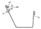
本発明の軒樋1は、基材層と、少なくとも前面板5の基材層の外側を耐候性樹脂で被覆した耐候性樹脂層から構成されている。基材層を構成する樹脂としては特に限定されず、例えば、塩化ビニル樹脂、アクリル樹脂、ポリカーボネート樹脂、ポリエチレンテレフタレート樹脂、ポリオレフィン樹脂、ポリウレタン樹脂、ポリスチレン樹脂、これらを変性させた樹脂類、若しくはこれらの樹脂の共重合樹脂類等の熱可塑性合成樹脂、或は、鉄やアルミニウムなどの金属、ガラス繊維、カーボン繊維、紙材、フィラー、などを芯材とし、その両面に合成樹脂を被覆してなる基材層により作製されている。また、耐候性樹脂としては特に限定されず、例えば、AES(アクリルニトリル−エチレンプロピレンジエン共重合体−スチレン共重合体)、ASA(アクリルニトリル−スチレン−アクリレート共重合体)、PMMA(ポリ−メチル−メタクリレート)等が挙げられる。これ以外にも、紫外線吸収剤、紫外線遮蔽剤、紫外線反射剤等を配合した熱可塑性樹脂であってもよい。
The eaves 1 of the present invention includes a base material layer and a weather resistant resin layer in which at least the outer surface of the base plate layer of the
本発明の軒樋の形状は、第一の軒樋1Aの内面側に第二の軒樋1Bの外面を沿わせて積載される、断面が上方に広がりを有する略凹状の形状である。前面板5と後面板3が同じ高さであって問題がない。図1に示すごとく、少なくとも前面板5の外側表面が耐候性樹脂で被覆されている軒樋にあって、底壁(図示略)の一端から外側に傾斜して立設された前面板5の上端に内側に突設した前耳部4、および、後面板3の上端に外側に突設した後耳部2を備え、この前耳部4、4同士と後耳部2、2同士とがそれぞれ上下に重なって積載される軒樋において、(イ)前耳部4の屋内側端縁部に係止凸部41を形成して、前面板5の上側前面板51と下側前面板52との間に外側から内側に凹没する係止凹溝6を有して、(ロ)上側前面板51は、下側前面板52の延長線上より外側に位置して、(ハ)上側前面板51と係止凹溝6との間に、水切りリブ7を下方に突設している。
The shape of the eaves rod according to the present invention is a substantially concave shape in which the cross-section of the first eave ridge 1A is stacked along the outer surface of the second eave ridge 1B and has a cross section extending upward. There is no problem because the
係止凹溝の大きさ61は、係止凸部の高さ41Hを超えない範囲が好ましい。係止凹溝の大きさ61が、係止凸部41の高さ41Hより大きくなると、軒樋1A,1Bを複数積載する際に、係止凹溝6と係止凸部41との重ねに支障が出る場合がある。
The size 61 of the locking groove is preferably in a range not exceeding the
上側前面板51は、下側前面板52の延長線上より間隔b102を隔てて外側に位置している。間隔b102は、下側前面板52の厚みより大きく、係止凹溝6の大きさ61より小さいのが好ましい。間隔b102が下側前面板52の厚みよりも小さいと、軒樋1A,1Bを複数積載する際に、前面板5の外側表面の耐候性樹脂層が係止凸部41と接触して、耐候性樹脂層に擦り傷が付く恐れがある。一方、間隔b102が係止凹溝6の大きさ61を超えると、係止凹溝6が形成できなくなる恐れがある。
The
図1および図2に示すごとく、上側前面板と係止凹溝との間に水切りリブ7を下方に突設すると、この軒樋本体1を軒先(図示略)などに吊着した際に、軒樋本体1を伝う雨水などがあったとしても、この水切りリブ7によって、雨水が落下して、軒樋本体1の底部裏面や軒先にまで雨水などが伝うことがなく、軒先が濡れたり、汚れたりするのを阻止できるものである。さらに、水切りリブ7先端が係止凹溝6の上部に当接することで、複数の軒樋1A,1Bを積載した際に、前述した間隔b102の効果と合わせて、前面板5の外側表面の耐候性樹脂層に擦り傷が付くのを防止できる。
As shown in FIG. 1 and FIG. 2, when the
図1〜図3に示すごとく、係止凹溝6と係止凸部41とが、互いに重なり合う断面略円形状にそれぞれ形成されているために、前耳部4、4同士と後耳部2、2同士とを、それぞれ上下に重ねると、係止凸部41と係止凹溝6とがスムーズに当接して、軒樋本体1A,1B同士の積載が確実なものとなり、荷崩れが防止できる。
As shown in FIG. 1 to FIG. 3, the locking groove 6 and the
図3に示すごとく、係止凸部41の上面と水切りリブ7の先端との間隔a100が、後耳部2の高さ101と同じであるので、軒樋本体1A,1B同士の積載がさらに確実なものとなる。
As shown in FIG. 3, since the distance a100 between the upper surface of the
図2に示すごとく、係止凸部41の上部に係止リブ411を突設させると、係止凹溝6と係止凸部41との当接が、さらに確実なものとなる。また、後耳部2の下部に凹み21を設けると、後耳部2、2同士の積載がより確実なものとなる。
As shown in FIG. 2, when the
本発明の軒樋は、複数の軒樋本体1A,1B同士を積載しても、前面板に擦り傷が付きにくい軒樋である。 The eaves bowl of the present invention is an eaves bowl which is less likely to be scratched on the front plate even when a plurality of eaves main bodies 1A and 1B are stacked.
さらに、下側の軒樋本体1Aと上側の軒樋本体1Bの、後耳部2、2同士が重なり、そして、上側の軒樋本体1Bの係止凹溝6と下側の軒樋本体1Aの係止凸部41とが当接しているので、下側の軒樋本体1Aの内面に上側の軒樋本体1Bの外面を沿わせて軒樋1を複数次々に積載して梱包することができて、梱包の効率が高くなるものである。
Further, the rear ears 2 and 2 of the lower eaves main body 1A and the upper eaves main body 1B overlap each other, and the locking groove 6 of the upper eaves main body 1B and the lower eaves main body 1A Since the
1、1A、1B 軒樋
2 後耳部
21 凹み
3 後面板
4 前耳部
41 係止凸部
41H 高さ
411 係止リブ
5 前面板
51 上側前面板
52 下側前面板
6 係止凹溝
61 係止凹溝の大きさ
7 水切りリブ
100 間隔a
101 高さ
102 間隔b
1, 1A, 1B Eaves 2
101
Claims (4)
(イ)前耳部の屋内側端縁部に係止凸部を形成して、前面板の上側前面板と下側前面板との間に外側から内側に凹没する係止凹溝を有している。
(ロ)上側前面板は、下側前面板の延長線上より外側に位置する。
(ハ)上側前面板と係止凹溝との間に、水切りリブを下方に突設する。 A front ear portion projecting inwardly at the upper end of the front plate that is inclined to the outside from one end of the bottom wall in an eaves bowl whose outer surface of the front plate is coated with weatherproof resin, and In the eaves provided with a rear ear projecting outward at the upper end of the rear plate, and loaded along the outer surface of the second eaves on the inner surface side of the first eaves, the following (a) to ( C) Eaves with
(B) A locking projection is formed on the indoor side edge of the front ear, and a locking groove is provided between the upper front plate and the lower front plate of the front plate so as to be recessed from the outside to the inside. is doing.
(B) The upper front plate is located outside the extended line of the lower front plate.
(C) A draining rib is projected downward between the upper front plate and the locking groove.
The eaves bowl according to any one of claims 1 to 3, wherein a locking rib protrudes from the locking projection.
Priority Applications (1)
| Application Number | Priority Date | Filing Date | Title |
|---|---|---|---|
| JP2007167363A JP2009007744A (en) | 2007-06-26 | 2007-06-26 | Eaves |
Applications Claiming Priority (1)
| Application Number | Priority Date | Filing Date | Title |
|---|---|---|---|
| JP2007167363A JP2009007744A (en) | 2007-06-26 | 2007-06-26 | Eaves |
Publications (1)
| Publication Number | Publication Date |
|---|---|
| JP2009007744A true JP2009007744A (en) | 2009-01-15 |
Family
ID=40323098
Family Applications (1)
| Application Number | Title | Priority Date | Filing Date |
|---|---|---|---|
| JP2007167363A Pending JP2009007744A (en) | 2007-06-26 | 2007-06-26 | Eaves |
Country Status (1)
| Country | Link |
|---|---|
| JP (1) | JP2009007744A (en) |
Cited By (1)
| Publication number | Priority date | Publication date | Assignee | Title |
|---|---|---|---|---|
| JP2011084961A (en) * | 2009-10-16 | 2011-04-28 | Mitsubishi Plastics Inc | Eaves gutter |
Citations (2)
| Publication number | Priority date | Publication date | Assignee | Title |
|---|---|---|---|---|
| JPH0913602A (en) * | 1995-06-30 | 1997-01-14 | Matsushita Electric Works Ltd | Eaves gutter and its stacking structure |
| JPH10121678A (en) * | 1996-10-25 | 1998-05-12 | Matsushita Electric Works Ltd | Eaves trough |
-
2007
- 2007-06-26 JP JP2007167363A patent/JP2009007744A/en active Pending
Patent Citations (2)
| Publication number | Priority date | Publication date | Assignee | Title |
|---|---|---|---|---|
| JPH0913602A (en) * | 1995-06-30 | 1997-01-14 | Matsushita Electric Works Ltd | Eaves gutter and its stacking structure |
| JPH10121678A (en) * | 1996-10-25 | 1998-05-12 | Matsushita Electric Works Ltd | Eaves trough |
Cited By (1)
| Publication number | Priority date | Publication date | Assignee | Title |
|---|---|---|---|---|
| JP2011084961A (en) * | 2009-10-16 | 2011-04-28 | Mitsubishi Plastics Inc | Eaves gutter |
Similar Documents
| Publication | Publication Date | Title |
|---|---|---|
| JP2009007744A (en) | Eaves | |
| JPH0122036Y2 (en) | ||
| JP3185957U (en) | Baseboard for remodeling and baseboard structure in renovation building using the same | |
| JP2014118708A (en) | Drain partition member of balcony and balcony structure using the same | |
| JP5497402B2 (en) | Eaves | |
| JP3178219B2 (en) | Eave gutter loading structure | |
| JP2010189878A (en) | Road sign | |
| JP5965631B2 (en) | Roof structure and roof construction method | |
| JP5046986B2 (en) | Roofing material | |
| JPH0913601A (en) | Eaves gutter and its stacking structure | |
| CN112727310B (en) | Cabinet component structure including glass window and cabinet | |
| JP3108354U (en) | Food containers | |
| JPH0913602A (en) | Eaves gutter and its stacking structure | |
| JP5270195B2 (en) | Plastic pipe for greenhouse | |
| JP4059179B2 (en) | Eaves mounting structure | |
| JP5643565B2 (en) | Connecting structure of daylighting roof | |
| JP7254728B2 (en) | Door body and fittings | |
| JP2530482Y2 (en) | Multifunctional multilayer board | |
| JPH0126831Y2 (en) | ||
| JP4334989B2 (en) | Roofing material | |
| KR200367690Y1 (en) | A reinforcements of mud board for construction | |
| JPH0352331Y2 (en) | ||
| TWM523676U (en) | Improvement of the structure of the storage box cover (12) | |
| KR200471187Y1 (en) | Whiteboard have thin edging around | |
| JPS5940550Y2 (en) | Eave structure for bay window |
Legal Events
| Date | Code | Title | Description |
|---|---|---|---|
| A621 | Written request for application examination |
Effective date: 20100614 Free format text: JAPANESE INTERMEDIATE CODE: A621 |
|
| A977 | Report on retrieval |
Effective date: 20120323 Free format text: JAPANESE INTERMEDIATE CODE: A971007 |
|
| A131 | Notification of reasons for refusal |
Free format text: JAPANESE INTERMEDIATE CODE: A131 Effective date: 20120417 |
|
| A521 | Written amendment |
Effective date: 20120608 Free format text: JAPANESE INTERMEDIATE CODE: A523 |
|
| A131 | Notification of reasons for refusal |
Free format text: JAPANESE INTERMEDIATE CODE: A131 Effective date: 20121016 |
|
| A02 | Decision of refusal |
Effective date: 20130226 Free format text: JAPANESE INTERMEDIATE CODE: A02 |