JP2009007796A - Walkway on folded plate roof - Google Patents
Walkway on folded plate roof Download PDFInfo
- Publication number
- JP2009007796A JP2009007796A JP2007168788A JP2007168788A JP2009007796A JP 2009007796 A JP2009007796 A JP 2009007796A JP 2007168788 A JP2007168788 A JP 2007168788A JP 2007168788 A JP2007168788 A JP 2007168788A JP 2009007796 A JP2009007796 A JP 2009007796A
- Authority
- JP
- Japan
- Prior art keywords
- roof
- folded plate
- walkway
- folded
- plate roof
- Prior art date
- Legal status (The legal status is an assumption and is not a legal conclusion. Google has not performed a legal analysis and makes no representation as to the accuracy of the status listed.)
- Pending
Links
- 238000010276 construction Methods 0.000 claims abstract description 17
- 239000000463 material Substances 0.000 claims description 58
- 238000009434 installation Methods 0.000 description 8
- 229910000831 Steel Inorganic materials 0.000 description 7
- 239000010959 steel Substances 0.000 description 7
- 239000002184 metal Substances 0.000 description 3
- 238000012423 maintenance Methods 0.000 description 2
- 230000003044 adaptive effect Effects 0.000 description 1
- 230000032683 aging Effects 0.000 description 1
- 238000010586 diagram Methods 0.000 description 1
- 238000009413 insulation Methods 0.000 description 1
- 238000012986 modification Methods 0.000 description 1
- 230000004048 modification Effects 0.000 description 1
- 238000005507 spraying Methods 0.000 description 1
- 238000004078 waterproofing Methods 0.000 description 1
Images


Landscapes
- Roof Covering Using Slabs Or Stiff Sheets (AREA)
Abstract
Description
この発明は、折板屋根上のメンテナンス用に設置される歩廊の技術分野に属し、更に言えば、既成の仮設足場板や金物を使用し、更に折板屋根の構築に使用された屋根用連結ボルト(又は折板屋根ルーフボルトとも呼ぶ。)を利用して簡易に縦横に設置される歩廊の技術分野に属する。 The present invention belongs to the technical field of walkways installed for maintenance on folded-plate roofs, and more specifically, the use of existing temporary scaffolding boards and hardware, and further the connection for roofs used for the construction of folded-plate roofs It belongs to the technical field of corridors that are simply installed vertically and horizontally using bolts (or folded plate roof roof bolts).
従来、金属製折板を使用して構築される折板屋根は、下記の特許文献1〜3を挙示したように種々公知であり、広く実施されている。
こうした折板屋根に関しても、部材の老朽化や破損等の有無、あるいは雨漏りなどの点検や修理のために、折板屋根上を安全に自由に歩けるメンテナンス歩廊(以下、歩廊という。)の必要性が大である。ところが従来、折板屋根の構造的特徴や機能に適合する構成の歩廊、あるいは折板屋根の構築後に施工性良く設置でき、軽量構造で、配置の自由度が高く、ハンドリング性の良い歩廊が見当たらないため、通例は直接、折板屋根上をその凹凸形状に足を取られながら歩いているのが実情である。
Conventionally, the folded-plate roof constructed | assembled using metal folding plates is well-known and widely implemented so that the following patent documents 1-3 were enumerated.
With regard to such folded plate roofs, there is a need for a maintenance walkway (hereinafter referred to as a walkway) that allows the user to safely and freely walk on the folded plate roof in order to check for and repair parts such as aging and damage, or leaking rain. Is big. However, if you find a walkway with a structure that fits the structural features and functions of the folded-plate roof, or can be installed with good workability after construction of the folded-plate roof, a lightweight structure with a high degree of freedom in arrangement and good handling Since there is no such thing, it is usually the case that you are walking directly on the folded-plate roof with your rugged shape.
本発明の目的は、折板屋根の凹凸形状を苦にすることなく歩くことができ、むしろ折板屋根に固有の凹凸形状を活用して、同折板屋根上のほぼ全面にわたり設置して、折板屋根上を安全に自由に歩いて点検、修理を行うことができる歩廊を提供することである。
本発明の次の目的は、折板屋根の構造的特徴や機能を活用して、折板屋根の構築後でも自由に施工性良く設置することができ、しかも軽量構造で、屋根上の点検その他の必要性と目的に応じて縦横に設置でき、配置の自由度が高く、ハンドリング性の良い歩廊を提供することである。
The purpose of the present invention is to walk without making the uneven shape of the folded-plate roof painful, rather, using the uneven shape inherent to the folded-plate roof, installing it over almost the entire surface of the folded-plate roof, The purpose is to provide a corridor that can be safely inspected and repaired on a folded roof.
The next object of the present invention is to utilize the structural features and functions of the folded-plate roof, and can be installed freely with good workability even after construction of the folded-plate roof. It is to provide a walkway that can be installed vertically and horizontally according to the necessity and purpose, and has a high degree of freedom in arrangement and good handling.
上述した従来技術の課題を解決するための手段として、請求項1に記載した発明に係る折板屋根上の歩廊は、
屋根架構の梁1上に折板3を敷設して構築された折板屋根の上面に、折板3の折り筋と同方向に設置された歩廊W1であって、
前記折板屋根の隣接する少なくとも二山の間に跨る受け材5が架け渡され、同受け材5の両端が当該折板屋根の構築に使用した屋根用連結ボルト4A又は4Bを利用して固定されており、
前記受け材5の上に、歩廊材7が、折板3の折り筋と同方向に架設されており、
前記歩廊材7の上面を横断方向に押さえ付けた固定バンド8の両端8aが、前記受け材5とボルト9で接合されていることを特徴とする。
As a means for solving the above-described problems of the prior art, a walkway on a folded plate roof according to the invention described in claim 1 is:
On the upper surface of the folded plate roof constructed by laying the folded
A receiving
A
Both ends 8 a of the
請求項2に記載した発明に係る折板屋根上の歩廊は、
屋根架構の梁1上に、折板3を敷設して構築された折板屋根の上面に、折板3の折り筋と直交する配置に設置された歩廊W2であって、
前記折板屋根の折り筋と直交する配置で、同折板屋根の各山頂上に歩廊材7が載置されており、
前記歩廊材7の上面を横断方向に押さえ付けた固定バンド8の両端8aが、当該折板屋根の構築に使用した屋根用連結ボルト4A又は4Bを利用して固定されていることを特徴とする。
The walkway on the folded roof according to the invention described in
On the upper surface of the folded plate roof constructed by laying the folded
In the arrangement perpendicular to the folding line of the folded plate roof, the
Both
請求項1に係る発明は、折板屋根の上面に、折板3の折り筋と同方向に歩廊W1を設置するにあたり、折板屋根の隣接する少なくとも二山の間に跨るように架け渡した受け材5の両端を、当該折板屋根の構築に使用した屋根用連結ボルト4A又は4Bを利用して固定し、前記受け材5の上に、歩廊材7を、折板3の折り筋と同方向に架設し、同歩廊材7の上面を横断方向に押さえ付けた固定バンド8の両端8aを、前記受け材5とボルト9により接合して固定した構成であるから、正に折板屋根の構造的特徴と機能を活用して、折板屋根の構築後でも、簡易に施工性良く、設置場所を自由に選んで設置することができる。
In the invention according to claim 1, when installing the corridor W <b> 1 in the same direction as the folding line of the folded
しかも歩廊材7には既往の足場板などを使用できるほか、固定バンド8や受け材5にしても建築現場にありあわせた屋根工事用の副資材や適応金物を利用して設置することができる。かくして安価に、軽量構造に、しかも屋根上に必要とされる場所や数量をことさら制限されることもなく歩廊W1を設置できる。
そして、使用上の必要がなくなった歩廊W1は、撤去したり設置場所を変更する配置替えなどの自由度も高いし、ハンドリング性の良さを有するのである。
In addition to the existing
And the walkway W1, which is no longer necessary for use, has a high degree of freedom such as removal or change of installation location, and has good handling properties.
請求項2に係る発明も、折板屋根の上面に、折板3の折り筋と直交する配置に歩廊W2を設置するにあたり、折板屋根の折り筋と直交する配置で、同折板屋根の各山頂上に歩廊材7を載置し、その上面を横断方向に押さえ付けた固定バンド8の両端8aを、当該折板屋根の構築に使用した屋根用連結ボルト4A又は4Bを利用して固定し設置するから、やはり折板屋根の構造的特徴と機能を活用して、折板屋根の構築後でも簡易に施工性良く設置することができる。歩廊W2の設置に必要な資材も、固定バンド8のみで足りる便利さと経済性の良さがある。
In the invention according to
以上のようにして、本発明の歩廊W1、W2は、折板屋根の完成後に自由に設置できるので、屋根の鉄骨製作図段階で、歩廊設置のための検討は無用であり、屋根面上へ自由なルートで配置できる。
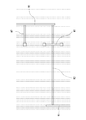
そして、請求項1に係る発明のように折板3の折り筋と同方向に設置する歩廊W1と、請求項2に係る発明のように折板3の折り筋と直交する配置に設置する歩廊W2とを、要所要所で相互に歩行可能に接続した配置で設置すると、図9に例示したように、折板屋根の上面に、縦横な配置で、必要なだけ、或いは隅々にまで歩廊W1、W2を軽便に設置することができる。よって、この歩廊W1、W2を利用すると、折板屋根の老朽化や破損等の有無、あるいは雨漏りなどの点検や修理のために屋根上を安全に自由に歩き回れるのである。
As described above, the corridors W1 and W2 of the present invention can be freely installed after the folded-plate roof is completed. Therefore, it is not necessary to examine the corridor installation at the stage of the steel frame drawing of the roof. Can be arranged with free route.
And the walkway W1 installed in the same direction as the crease of the
折板屋根の上面に、折板3の折り筋と同方向に設置する歩廊W1は、折板屋根の隣接する少なくとも二山の間に跨る受け材5を架け渡し、同受け材5の両端は、当該折板屋根の構築に使用した屋根用連結ボルト4A又は4Bを利用して固定する。
その上で、前記受け材5上に、歩廊材7を、折板3の折り筋と同方向に架設し、前記歩廊材7の上面を横断方向に押さえ付けた固定バンド8の両端8aは、前記受け材5とボルト9で接合して設置する。
The corridor W1 installed on the upper surface of the folded plate roof in the same direction as the folding line of the folded
Then, both
また、折板3の折り筋と直交する配置に設置する歩廊W2は、折板屋根の折り筋と直交する配置で、同折板屋根の各山頂上に歩廊材7を載置し、前記歩廊材7の上面を横断方向に押さえ付けた固定バンド8の両端8aは、当該折板屋根の構築に使用した屋根用連結ボルト4A又は4Bを利用して固定し設置する。
かくして折板屋根の折り筋と同方向に設置された歩廊W1(図1)と、折板屋根の折り筋と直交する配置に設置された歩廊W2(図6)とを、相互に歩行できる状態に接続することにより、折板屋根の上面に歩廊W1、W2を縦横に設置できる(図9)。
The walkway W2 installed in an arrangement perpendicular to the folding line of the folded
Thus, a state where the walkway W1 (FIG. 1) installed in the same direction as the folding line of the folded-plate roof and the walkway W2 (FIG. 6) installed in an arrangement orthogonal to the folding line of the folded-plate roof can be walked with each other. By connecting to, the walkways W1 and W2 can be installed vertically and horizontally on the upper surface of the folded roof (FIG. 9).
図1は、折板屋根上に、折板3の折り筋と同方向に設置された歩廊W1の実施例を部分的に示している。
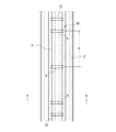
この折板屋根は、通例は図5に例示したように、屋根架構を構成する鉄骨梁1の上面に固定して用意された、折板断面とほぼ同形・同大の波形状をなすタイトフレーム2の上に、鋼板等を加工して略V字形の一山半タイプ、又は略W字形の二山半タイプ等に成形れた金属折板3の山同士を相互に重ね合わせ、前記タイトフレーム2が存在する場所では、タイトフレーム2とその上に重ねた2枚の折板3を上向きに使用した屋根用連結ボルト4Aで合一に連結する。また、鉄骨梁1およびタイトフレーム2のスパン間でも折板相互の連結が必要な位置では、やはり上向きに使用した屋根用連結ボルト4Bで2枚の折板3、3同士を合一に連結して折板屋根が構築されている。因みに前記鉄骨梁1およびタイトフレーム2のスパンは通例3m〜7m程度、金属折板3の山間のピッチは、通例約45cm程度、山の高さは200mm程度、板厚は0.6〜1.2mm程度である。
FIG. 1 partially shows an embodiment of a walkway W <b> 1 installed on the folded plate roof in the same direction as the folding line of the folded
As shown in FIG. 5, this folded plate roof is usually prepared by being fixed to the upper surface of the steel beam 1 constituting the roof frame, and a tight frame having a wave shape substantially the same shape and the same size as the folded plate section. 2 is formed by superimposing piles of metal folded
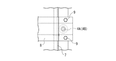
上記のように構築された折板屋根の上面に、図1のように折板3の折り筋と同方向に歩廊W1を設置するにあたっては、図2〜図4に詳示したように、前記折板3の隣接する二山の間(但し、二山の限りではなく、二山以上の複数山でも可。)に跨る配置で、本実施例の場合は、図3に示したハット型の軽量形鋼を倒立状態に用いた受け材5が架け渡され、同受け材5の両端は、倒立ハット型の溝底部分を、当該折板屋根の構築に上向きに使用した上記屋根用連結ボルト4A又は4Bのいずれかを利用しナット6を締結して強固に固定して設置されている。つまり、歩廊W1の長手方向に、歩廊材の支持に適切なピッチで配置する受け材5は、前記配置に適合する位置の屋根用連結ボルト4A又は4Bのいずれかを選択して利用し、その両端を固定する。
In installing the corridor W1 in the same direction as the folding line of the folded
そして、上記受け材5の上に、歩廊材7が折板3の折り筋と同方向に架設されている。因みにここで使用する歩廊材7は、特別仕様の資材を指すのではなく、例えば特開平10−8709号公報に記載された通路部材とか、既往の足場板など、基本的に当該屋根工事現場に存在するもので利用できれば足りる。
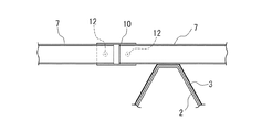
受け材5の上に架設された歩廊材7は、同歩廊材7の上面を横断方向に押さえ付けた固定バンド8の両端8aが、前記受け材5のフランジ部へボルト9で接合して固定されている。つまり、固定バンド8の配置は、上記受け材5の位置に一致させる。固定バンド8には、やはり現場にありあわせの幅が100mm程度の帯状薄鋼板などを折り曲げ加工したものを利用できる。受け材5および固定バンド8は、図1に示したように、歩廊材7の長さを約4mとして、歩廊材7の長手方向に約1.5m程度の間隔Pをあけて設置される。なお、図1中の符号10は歩廊材7同士の接続部を指している。この接続部10の構造については、実施例2を示す図8に基づいて後で説明する。図1の接続部10の間隔は、当然、1枚の歩廊材7の長さ4m毎に設けられている。
On the
The
上記の通りであるから、本実施例の歩廊W1は、折板屋根の隣接する少なくとも二山の間に受け材5を架け渡し、その両端を屋根用連結ボルト4A又は4Bのいずれかを利用して固定し、前記受け材5の上に歩廊材7を架設する構成であるから、設置のルートや場所を任意自在に選んで高い自由度で設置することができる。もとより、固定バンド8を固定したボルト9を取り外し、更に受け材5を撤去することにより、歩廊W1の撤去、或いは設置ルートの変更も自在に行うことができるハンドリング性の良さも兼ね備えている。
Since it is as above-mentioned, the walkway W1 of a present Example bridges the receiving
次に、図6〜図8に基づいて、請求項2に記載した発明に係る、折板3の折り筋と直交する配置に設置された歩廊W2の実施例を説明する。
本実施例の場合も、一例として示した図5のように構築された折板屋根を前提として、同折板屋根の上面に、図6に示すように、折板3の折り筋と直交する配置で歩廊W2を設置するにあたり、先ずは折板屋根の各山頂上を跨ぐように、歩廊材7が載置される。そして、歩廊材7の長手方向に、折板屋根の凹凸にして一ないし複数個の間隔(図6の実施例では一つおきの間隔)を開けた山頂毎の位置であって、上記屋根用連結ボルト4A又は4Bが存在する位置を選択して、図7に示したように、前記歩廊材7の上面を横断方向に押さえ付けた固定バンド8の両端8aが、前記屋根用連結ボルト4A又は4Bのいずれかをを利用しナット11を締め付け固定して歩廊W2が設置されている。
Next, based on FIGS. 6-8, the Example of the corridor W2 installed in the arrangement | positioning orthogonal to the crease of the folded
Also in the case of the present embodiment, assuming the folded plate roof constructed as shown in FIG. 5 as an example, the upper surface of the folded plate roof is orthogonal to the folding line of the folded
なお、図8は、長手方向に突き合わせ接続された歩廊材7の接続構造を示している。図示した接続構造は、相互に突き合わせ接続される歩廊材7、7の端部を筒形の接続具10に嵌め込んで接続し、更に接続具10は止めネジ12で各歩廊材7、7の端部へ固定して接続構造の安定化が図られている。この接続構造は、上述した実施例1の歩廊材の接続構造10としても同様に実施される。
In addition, FIG. 8 has shown the connection structure of the
本実施例2の場合にも、歩廊W2の設置ルートや設置場所は、任意自在に選んで高い自由度で設置することができる。また、歩廊材7の上面を横断方向に押さえ付けた固定バンド8のナット11をゆるめて外すことにより、当該歩廊W2の撤去、或いは設置ルートの変更を軽便に自在に行うことができるハンドリングの良さもある。
Also in the case of the present Example 2, the installation route and installation place of the corridor W2 can be chosen arbitrarily and can be installed with a high degree of freedom. Further, by loosening and removing the
図9は、以上に説明した実施例1の折板3の折り筋と同方向に設置された歩廊W1と、上記実施例2で説明した折板3の折り筋と直交する配置に設置された歩廊W2とを、それぞれ折板屋根上の必要な場所に必要なルートで設置して、相互間を歩行できる状態に接続することにより、広い折板屋根上の全面にわたり、必要十分な配置と位置を満足する歩廊W1、W2を縦横に設置した実施例を示している。
FIG. 9 shows the corridor W1 installed in the same direction as the folding line of the
以上に、本発明を図示した実施例に基づいて説明したが、もとより本発明は図示した実施例の範囲に限定されるものではない。本発明の目的と要旨を逸脱しない範囲で、当業者が必要に応じて行う設計変更をはじめとする変形、応用を含むものである。例えば折板屋根の断熱・防水処理に関しては公知の吹き付けシステムで施工すること、或いは歩廊W1、W2の必要に応じて手摺りを設置することなども必要に応じて実施されることを念のため申し述べる。 Although the present invention has been described based on the illustrated embodiment, the present invention is not limited to the scope of the illustrated embodiment. The present invention includes modifications and applications including design changes made by those skilled in the art as needed without departing from the scope and spirit of the present invention. For example, with regard to the heat insulation and waterproofing treatment of the folded-plate roof, it is to be noted that construction with a known spraying system or installation of handrails as required for the walkways W1 and W2 is also carried out as necessary. I will tell you.
W1、W2 歩廊
1 梁
2 タイトフレーム
3 折板
4A、4B 屋根用連結ボルト
5 受け材
7 歩廊材
8 固定バンド
9 ボルト
W1, W2 Walkway 1 Beam
2
Claims (2)
前記折板屋根の隣接する少なくとも二山の間に跨る受け材が架け渡され、同受け材の両端が当該折板屋根の構築に使用した屋根用連結ボルトを利用して固定されており、
前記受け材の上に、歩廊材が、折板の折り筋と同方向に架設されており、
前記歩廊材の上面を横断方向に押さえ付けた固定バンドの両端が、前記受け材とボルト接合により固定されていることを特徴とする、折板屋根上の歩廊。 A walkway installed in the same direction as the folding line of the folded plate on the upper surface of the folded plate roof constructed by laying the folded plate on the beam of the roof frame,
A receiving material straddling between at least two adjacent mountains of the folded plate roof is bridged, and both ends of the receiving material are fixed using the connecting bolts for the roof used for the construction of the folded plate roof,
On the receiving material, a walkway material is installed in the same direction as the folding line of the folded plate,
A walkway on a folded plate roof, wherein both ends of a fixed band that presses the upper surface of the walkway material in a transverse direction are fixed to the receiving member by bolting.
前記折板屋根の折り筋と直交する配置で、同折板屋根の各山頂上に歩廊材が載置されており、
前記歩廊材の上面を横断方向に押さえ付けた固定バンドの両端が、当該折板屋根の構築に使用した屋根用連結ボルトを利用して固定されていることを特徴とする、折板屋根上の歩廊。 On the upper surface of the folded plate roof constructed by laying folded plates on the beams of the roof frame, a walkway installed in an arrangement perpendicular to the folding lines of the folded plates,
In an arrangement perpendicular to the folding line of the folded plate roof, a walkway material is placed on each mountain top of the folded plate roof,
Both ends of the fixing band that presses the upper surface of the corridor material in the transverse direction are fixed using the connecting bolts for roof used for the construction of the folded plate roof, on the folded plate roof Walkway.
Priority Applications (1)
| Application Number | Priority Date | Filing Date | Title |
|---|---|---|---|
| JP2007168788A JP2009007796A (en) | 2007-06-27 | 2007-06-27 | Walkway on folded plate roof |
Applications Claiming Priority (1)
| Application Number | Priority Date | Filing Date | Title |
|---|---|---|---|
| JP2007168788A JP2009007796A (en) | 2007-06-27 | 2007-06-27 | Walkway on folded plate roof |
Publications (1)
| Publication Number | Publication Date |
|---|---|
| JP2009007796A true JP2009007796A (en) | 2009-01-15 |
Family
ID=40323149
Family Applications (1)
| Application Number | Title | Priority Date | Filing Date |
|---|---|---|---|
| JP2007168788A Pending JP2009007796A (en) | 2007-06-27 | 2007-06-27 | Walkway on folded plate roof |
Country Status (1)
| Country | Link |
|---|---|
| JP (1) | JP2009007796A (en) |
Cited By (4)
| Publication number | Priority date | Publication date | Assignee | Title |
|---|---|---|---|---|
| WO2016104138A1 (en) * | 2014-12-26 | 2016-06-30 | 綿半鋼機株式会社 | Eave inspection corridor |
| CN109057175A (en) * | 2018-09-19 | 2018-12-21 | 中铁第四勘察设计院集团有限公司 | Metal Roof system with maintenance riding track |
| CN109457876A (en) * | 2018-12-17 | 2019-03-12 | 中铁第四勘察设计院集团有限公司 | Metal Roof system with concealed type maintenance riding track |
| JP2023058838A (en) * | 2021-10-14 | 2023-04-26 | 日栄インテック株式会社 | Corridor plate |
-
2007
- 2007-06-27 JP JP2007168788A patent/JP2009007796A/en active Pending
Cited By (7)
| Publication number | Priority date | Publication date | Assignee | Title |
|---|---|---|---|---|
| WO2016104138A1 (en) * | 2014-12-26 | 2016-06-30 | 綿半鋼機株式会社 | Eave inspection corridor |
| CN109057175A (en) * | 2018-09-19 | 2018-12-21 | 中铁第四勘察设计院集团有限公司 | Metal Roof system with maintenance riding track |
| CN109057175B (en) * | 2018-09-19 | 2024-05-17 | 中铁第四勘察设计院集团有限公司 | Metal roofing system of area maintenance horse way |
| CN109457876A (en) * | 2018-12-17 | 2019-03-12 | 中铁第四勘察设计院集团有限公司 | Metal Roof system with concealed type maintenance riding track |
| CN109457876B (en) * | 2018-12-17 | 2024-03-26 | 中铁第四勘察设计院集团有限公司 | Metal roof system with hidden maintenance horse way |
| JP2023058838A (en) * | 2021-10-14 | 2023-04-26 | 日栄インテック株式会社 | Corridor plate |
| JP7633134B2 (en) | 2021-10-14 | 2025-02-19 | 日栄インテック株式会社 | Walkway Plate |
Similar Documents
| Publication | Publication Date | Title |
|---|---|---|
| AU6508096A (en) | Bridge platform | |
| CN103334579B (en) | Slipping platform used for mounting arched roof truss with steel structure | |
| JP2009007796A (en) | Walkway on folded plate roof | |
| JP7019660B2 (en) | Installation structure of lightweight lining board | |
| CN106894625B (en) | Modularized external hanging scaffold | |
| JP6066844B2 (en) | Deck foundation roof equipment installation foundation and construction method | |
| US11236473B2 (en) | Transition construction for bridging a building joint | |
| CN213204736U (en) | Unit-assembled type maintenance pavement for metal roof system | |
| JP6366171B2 (en) | Roof support equipment | |
| JP5748325B2 (en) | Solar panel mount for slate roof | |
| JP6474185B2 (en) | Solar power panel construction method | |
| JP5320516B1 (en) | Solar panel installation device | |
| KR20130096803A (en) | A expansion joint apparatus for bridge structure | |
| JP2009133093A (en) | Roof reinforcing method, roof reinforcing structure, roof reinforcing member, and installation fixing bracket | |
| JP6864547B2 (en) | Eaves inspection corridor | |
| KR200392341Y1 (en) | Fixing Device for Aerial Scaffolding | |
| JP5163032B2 (en) | Building | |
| KR101559064B1 (en) | Expansion joint device and execution method thereof | |
| CN207538492U (en) | A kind of combination tool formula faces side hole protector | |
| KR101390694B1 (en) | Waterproof top board structure for girder bridge and girder bridge using the same | |
| JP4881103B2 (en) | Fixing jig on slate roof | |
| CN211523712U (en) | Steel structure roof | |
| JP5601923B2 (en) | Attaching roof exterior materials | |
| JP6888192B2 (en) | Solar panel mounting structure | |
| JP7421285B2 (en) | How to repair a corrugated slate roof |