JP2009010507A - Image reading apparatus and image forming apparatus - Google Patents
Image reading apparatus and image forming apparatus Download PDFInfo
- Publication number
- JP2009010507A JP2009010507A JP2007167827A JP2007167827A JP2009010507A JP 2009010507 A JP2009010507 A JP 2009010507A JP 2007167827 A JP2007167827 A JP 2007167827A JP 2007167827 A JP2007167827 A JP 2007167827A JP 2009010507 A JP2009010507 A JP 2009010507A
- Authority
- JP
- Japan
- Prior art keywords
- correction data
- image
- read
- reading apparatus
- range
- Prior art date
- Legal status (The legal status is an assumption and is not a legal conclusion. Google has not performed a legal analysis and makes no representation as to the accuracy of the status listed.)
- Pending
Links
Images



Landscapes
- Image Input (AREA)
- Facsimile Heads (AREA)
- Facsimile Scanning Arrangements (AREA)
- Facsimile Image Signal Circuits (AREA)
Abstract
Description
本発明は、スキャナ、複写機等に使用される画像読取装置に関し、特に、大判サイズの原稿に対応するために、複数のイメージセンサを千鳥状に配置した画像読取装置及びこの画像読取装置を備えた画像形成装置に関する。
BACKGROUND OF THE
原稿画像を光電変換素子で構成されたイメージセンサで読み取り、得られた画像信号をデジタル画像信号に変換して画像データを得る画像読取装置は、スキャナ、複写機等に広く用いられている。このような画像読取装置において、大判サイズの原稿を読み取って画像データを得るためには、原稿の最大幅に対応する長さを有する1本の長尺なリニアイメージセンサおよび結像素子を設ける形式と、特許文献1に記載されているように、複数のリニアイメージセンサおよび結像素子を1つのライン上に結像させるように千鳥状に配列させた形式のものが知られている。更に、特許文献2に記載されているように、複数のリニアイメージセンサおよび結像素子を複数のライン上に結像させるように千鳥状に配列させた形式や、特許文献3に記載されているように、複数の縮小型イメージセンサに複数の縮小レンズで結像させるようにした形式のものも知られている。
An image reading apparatus that reads an original image with an image sensor including a photoelectric conversion element and converts the obtained image signal into a digital image signal to obtain image data is widely used in scanners, copiers, and the like. In such an image reading apparatus, in order to read a large-size original and obtain image data, a type in which one long linear image sensor having a length corresponding to the maximum width of the original and an imaging element are provided. As described in Japanese Patent Application Laid-Open No. H10-228707, a type in which a plurality of linear image sensors and imaging elements are arranged in a staggered manner so as to form an image on one line is known. Further, as described in
一方、イメージセンサにおいては、読み取った画像信号にシェーディングと呼ばれる出力ひずみが含まれている。この出力ひずみの原因としては、原稿を照射する光源の光量の変動や不均一さがある。 On the other hand, in an image sensor, an output distortion called shading is included in a read image signal. As a cause of this output distortion, there are fluctuation and non-uniformity of the light amount of the light source that irradiates the document.
そこで、電源投入後の画像読取開始前にシェーディング補正を行うことが提案されている。このシェーディング補正は、白基準板に光を照射し、センサで読み取った画像信号のレベルが在る目標値に達するようにアンプに与えるゲイン値を決定するようにしている。この技術は例えば特許文献4に記載されている。
Therefore, it has been proposed to perform shading correction before starting image reading after power-on. In this shading correction, the white reference plate is irradiated with light, and the gain value given to the amplifier is determined so that the level of the image signal read by the sensor reaches the target value. This technique is described in
光量変動に関しては、特許文献5ないし7に記載されているような技術が知られている。このうち特許文献5には、CCDの近傍に温度センサを設け、その検出温度を予め設定している温度及び暗時出力電圧の関係によって、出力値を補正する方法が記載されている。また、特許文献6には、光源の近傍に光量検出手段を配置して光源の光量そのものを補正する方法が記載されている。さらに、特許文献7には、画像読み取る部分と白基準板を読み取る部分とを備えたイメージセンサを用いて、白基準板を読み取るイメージセンサの出力により、光源の光量や色の変化を検出し、前記イメージセンサの画像を読み取る部分の出力を補正する方法などが記載されている。
ところで、A0判等の広幅の用紙を扱う画像形成装置等に用いる画像読取部を構成する機能要素、例えば画像読取部を構成するCCD等の読取素子を、幅広の画像形成装置の専用品として単一の長大なユニットとして製作すると、コスト的に不利となる。すなわち、幅広機専用の機能要素は開発費が高い割には、量産品にはならないために、コスト的に不利となる。また、広幅機特有の長尺の原稿(例えば15m)を読み取る際に、ランプの光量変動がしばしば起こり、濃度ムラ(例えば先端と後端に濃度の差が出る)が発生してしまう。 By the way, a functional element that constitutes an image reading unit used in an image forming apparatus or the like that handles wide paper such as A0 size, for example, a reading element such as a CCD that constitutes the image reading unit is simply used as a dedicated product for a wide image forming apparatus. Producing as one long unit is disadvantageous in terms of cost. In other words, the functional elements dedicated to wide machines are disadvantageous in terms of cost because they are not mass-produced products for a high development cost. In addition, when reading a long document (for example, 15 m) unique to a wide-width machine, the light quantity of the lamp often changes, resulting in density unevenness (for example, a density difference between the leading edge and the trailing edge).
そこで、本発明が解決しようとする課題は、長尺の原稿の読取データをリアルタイム補正することができるようにし、長尺原稿を読み取る間の光源の光量変動による濃度ムラの発生を防ぐことにある。 Therefore, a problem to be solved by the present invention is to enable real-time correction of reading data of a long document, and to prevent density unevenness due to light amount fluctuation of the light source during reading of the long document. .
前記目的を達成するため、第1の手段は、最大読取幅より小さいイメージセンサと原稿を照射する光源を複数用い、個々のイメージセンサと光源の有効画素範囲を含む端部が、オーバラップするように千鳥配置し、個々のイメージセンサからの出力をつなぎ合わせて大判サイズの原稿を読み取る可能な画像読取装置において、前記イメージセンサの原稿読取範囲外であって有効読取範囲内に設定された補正データ作成範囲で読み取られる白基準部における原稿の読取開始時の読取データと、原稿読取時の読取データとから前記個々のイメージセンサ毎に補正データを作成し、この補正データに基づいて読取画像信号を補正する手段を備えていることを特徴とする。 In order to achieve the above object, the first means uses a plurality of image sensors smaller than the maximum reading width and a plurality of light sources for illuminating the document, so that the end portions including the effective pixel ranges of the individual image sensors overlap with each other. In an image reading apparatus capable of reading a large-size original by connecting outputs from individual image sensors together in a staggered manner, correction data set outside the original reading range of the image sensor and within the effective reading range Correction data is created for each individual image sensor from the read data at the start of reading of the document in the white reference portion read in the creation range and the read data at the time of reading the document, and the read image signal is generated based on the correction data. Means for correcting is provided.
第2の手段は第1の手段において、前記補正データが、前記補正データ範囲の1ライン中の予め設定された特定の領域の平均した値であることを特徴とする。 The second means is characterized in that, in the first means, the correction data is an average value of a predetermined specific area in one line of the correction data range.
第3の手段は第1の手段において、前記補正データに使用する補正データ範囲が、1ライン中の全範囲の領域の平均した値であることを特徴とする。 The third means is characterized in that, in the first means, the correction data range used for the correction data is an average value of the entire area in one line.
第4の手段は第1の手段において、前記補正データが、補正データ範囲の副走査の複数ライン分の単純平均値であることを特徴とする。 A fourth means is the first means characterized in that the correction data is a simple average value for a plurality of lines of sub-scanning of the correction data range.
第5の手段は第1の手段において、前記補正データが、補正データ範囲の副走査の複数ライン分の重加算平均した値であることを特徴とする。 A fifth means is characterized in that, in the first means, the correction data is a value obtained by averaging multiple additions for a plurality of sub-scans of the correction data range.
第6の手段は第1ないし第5の手段において、前記補正データが、前記イメージセンサの一端又は両端の補正データ作成範囲を使って作成することを特徴とする。 A sixth means is the first to fifth means, wherein the correction data is created using a correction data creation range at one or both ends of the image sensor.
第7の手段は第1ないし第6の手段において、電源投入直後は、電源投入時に生成された読取データを使用して補正データを作成し、電源が切られるまでは、前回生成した補正データを使用することを特徴とする。 The seventh means is the first to sixth means, wherein immediately after the power is turned on, the correction data is created using the read data generated at the time of power-on, and the previously generated correction data is used until the power is turned off. It is characterized by using.
第8の手段は、画像形成装置が第1ないし第7の画像読取装置を備えていることを特徴とする。 The eighth means is characterized in that the image forming apparatus includes first to seventh image reading apparatuses.
後述の実施形態において、イメージセンサは第1密着イメージセンサ(CIS)11、第2密着イメージセンサ(CIS)10、第3密着イメージセンサ(CIS)12に、原稿は参照番号9に、光源は第1、第2、第3光源31〜33に、補正する手段は21、第1信号処理部(AFE1)21、第2信号処理部(AFE2)22、第3信号処理部(AFE3)23にそれぞれ対応する。
In the embodiments described later, the image sensor is the first contact image sensor (CIS) 11, the second contact image sensor (CIS) 10, the third contact image sensor (CIS) 12, the document is the
本発明によれば、原稿読取範囲外にある有効読取範囲にある白基準部の読取データから補正データを作成し、補正データに基づいて、読取画像信号を補正するので、リアルタイムに読取データを補正することができる。また、読取部に近い場所で補正データを作成するので、高精度の補正を行うことができる。 According to the present invention, the correction data is created from the reading data of the white reference portion in the effective reading range outside the document reading range, and the read image signal is corrected based on the correction data, so the reading data is corrected in real time. can do. In addition, since correction data is created at a location close to the reading unit, high-precision correction can be performed.
以下、図面を参照し、本発明の実施形態について説明する。 Hereinafter, embodiments of the present invention will be described with reference to the drawings.
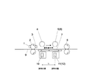
図1は本発明の実施形態に係る画像読取装置の機構概要を示す縦断面図、図2はその平面図である。この実施形態に係る画像読取装置は、原稿移動式の読取装置である。この画像読取装置では、イメージセンサは密着イメージセンサ(以下、CISと称する)を使用し、白基準部は3つのCISを千鳥状に配置して、大判サイズの原稿の幅一杯まで読み取ることができるようにしている。 FIG. 1 is a longitudinal sectional view showing an outline of the mechanism of an image reading apparatus according to an embodiment of the present invention, and FIG. 2 is a plan view thereof. The image reading apparatus according to this embodiment is a document moving type reading apparatus. In this image reading apparatus, a contact image sensor (hereinafter referred to as CIS) is used as an image sensor, and three CISs are arranged in a staggered manner in the white reference portion so that a full-size original can be read to the full width. I am doing so.
すなわち、画像読取装置は、原稿9をコンタクトガラス7上に送り出すための前方搬送ローラ対2と、この前方搬送ローラ対2から送り出され、コンタクトガラス7上を通過した原稿9を排出するための後方搬送ローラ対8と、白基準部とを備えている。白基準部は、図2に示すように、第1基準白ローラ5、第2基準白ローラ4及び第3基準白ローラ6からなる。これらの基準ローラ5,4,6は、千鳥状に配された第1CIS11、第2CIS10及び第3CIS12を上のコンタクトガラス7を挟んだ位置にそれぞれ設けられている。なお、図1において、第3基準白ローラ6は図示されていないが、この第3基準白ローラ6は第1基準白ローラ5と同一軸線上に位置しており、第1基準白ローラ5の背後側に隠れている。
That is, the image reading apparatus includes a front
前方搬送ローラ対2のうちの上方のローラの原稿搬送方向上流側には原稿9の先端部の搬送ローラ対2への挿入を検知する原稿挿入センサ1が、下流側には搬送ローラ対2のニップから送り出される原稿の先端を検知するレジストセンサ3が配置されている。
A
なお、この実施形態では、白基準部を白色ローラで構成しているが、白板で構成してもよく、この場合、白板はCIS毎にあってもよいし、1つの白板で3つのCIS上を覆ってもよい。 In this embodiment, the white reference portion is configured by a white roller. However, the white reference portion may be configured by a white plate. In this case, the white plate may be provided for each CIS, or one white plate on three CISs. May be covered.
本実施形態に係る画像読取装置では、原稿9は図1の左側から前方搬送ローラ対2間に挿入される。そして、原稿挿入センサ1が原稿9を検知すると、搬送モータ(不図示)により前方搬送ローラ対2、後方搬送ローラ対8が回転し、第1CIS11、第2CIS10及び第3CIS12内の原稿照明用光源(不図示)が点灯する。その後、レジストセンサ3により原稿9の先端を検知し、この先端検知タイミングを基準にして原稿9の搬送経路における位置が逐次認識される。原稿9の画像(下面)は第2CIS10で読み取られた後、第1CIS11及び第3CIS12に読み取られる。各CIS10,11,12によって読み取られた信号は、後段の画像処理部(不図示)で、第2CIS10の読取信号は第2CIS10と第1CIS11間の副走査に要する時間(距離:L)だけ遅延され、第1CIS11、第2CIS10及び第3CIS12の各信号は結合され、1ライン化された読取信号を得る構成になっている。この一連の流れを繰り返し、原稿9の画像は順次読み取られ、後方搬送ローラ対8を経て排出される。
In the image reading apparatus according to the present embodiment, the
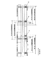
図2は、平面図であることから原稿は図において下側から上側へと搬送される。各第1CIS11、第2CIS10及び第3CIS12の有効読取範囲は隣接するCISの有効読取範囲と所定範囲重複して配置されている。また、これら第1CIS11、第2CIS10及び第3CIS12の原稿読取範囲も隣接するCISの原稿読取範囲と所定範囲重複して配置され、かつ各時点で使用する画像信号を得るための調整読取範囲W1,W2(画像の繋ぎ目部を作成する画像範囲)が設けられている。これにより、主走査方向である各調整読取範囲W1,W2は、独立して任意に設定することができる。なお、Aの部分が補正データとなる1ライン中の特定の領域である。この領域が補正データ作成範囲となり、補正データはこの部分の読取データの平均値を使用する。補正データに使用する補正データ範囲の1ライン中の特定の領域を任意に選択することによって原稿のサイズに合わせて補正データ領域を使用することができる。
Since FIG. 2 is a plan view, the document is conveyed from the lower side to the upper side in the drawing. The effective reading ranges of the
また、Aの部分は第1CIS11の一端部に設定しているが、他端側にも設定してもよい。CISの両端を補正データに使用すると、1箇所で作成する補正データより精度の高い補正データを作成することができる。
Further, the portion A is set at one end of the
更に、特定の領域は1ライン中としているが、補正データ範囲の副走査の複数ライン分の単純平均又は重加算平均した値を補正データとしてもよい。これにより、急激な変化に反応せず、滑らかな補正データにより補正を行うことができる。 Furthermore, although the specific area is in one line, a simple average or multiple addition average for a plurality of sub-scans in the correction data range may be used as the correction data. Thereby, it can correct | amend with smooth correction data, without reacting to a sudden change.
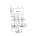
図3は画像読取装置の電気的な構成を示すブロック図である。画像読取装置は、各々1〜N個の読取画素を有する第1CIS11、第2CIS10及び第3CIS12CIと、これら第1CIS11、第2CIS10及び第3CIS12CIからの信号を処理する第1信号処理部(AFE1)21、第2信号処理部(AFE2)22及び第3信号処理部(AFE3)23と、第1CIS11、第2CIS10及び第3CIS12CIの画像信号を結合する信号処理及びメモリ部24と、第1CIS11、第2CIS10及び第3CIS12CIの光源の点灯制御を行うタイミング制御及びメモリ部25とから構成されている。各第1CIS11、第2CIS10及び第3CIS12CIは、それぞれ光源である第1、第2、第3光源31〜33と、第1、第2、第3基準白ローラ5、4、6を備えている。第1信号処理部(AFE1)21、第2信号処理部(AFE2)22及び第3信号処理部(AFE3)23はそれぞれ、図示していないが信号増幅部とA/D変換部とを有する。
FIG. 3 is a block diagram showing an electrical configuration of the image reading apparatus. The image reading apparatus includes a
図4はCISの出力からデジタル画像信号を得るための信号処理部の構成を示すブロック図である。図4は第1信号処理部21の詳細である。なお、第2及び第3信号処理部22,23も同様な構成になっている。この第1信号処理部21は、入力に対して交流結合後の入力端子電位を規定するためのクランプ回路(CLMP回路)211と、第1CIS11の出力信号の信号成分のみを取り出すサンプルホールド回路(SH回路)212と、指定した増幅率でサンプルホールド後の信号を増幅する可変ゲインアンプ(VGA)213と、アナログ信号をデジタル信号に変換するアナログデジタル変換回路(ADC)214と、1ラインのピークデータ検出を行い、ピーク値が白レベル目標値になるように可変ゲインアンプ213のゲインを調整する自動ゲインコントロール回路(AGC)215と、TG&I/F216などで構成されている。TG&IF216には、CLMPIN、SH、MCLK、SCLK、SD、CS、SHGTなどの各信号が入力される。これらの信号のうち、CLMPINはクランプ回路211に、SHはサンプルホールド回路212に、SHGTは自動ゲインコントロール回路215にTG&IF216を介して入力される。
FIG. 4 is a block diagram showing a configuration of a signal processing unit for obtaining a digital image signal from CIS output. FIG. 4 shows details of the first
図5は光量変動対策における各CISの読取範囲を説明するための図である。図5に示すように、原稿読取範囲外にあるイメージセンサの有効読取範囲を補正データ作成範囲Aとして使用し、補正データ作成範囲Aの各基準白ローラ5,4,6の読取データから光量変動時の補正データを作成する。
FIG. 5 is a diagram for explaining the reading range of each CIS in light quantity fluctuation countermeasures. As shown in FIG. 5, the effective reading range of the image sensor outside the document reading range is used as the correction data creation range A, and the amount of light fluctuations from the reading data of the reference
図6は光量変動対策の動作を説明するフローチャートである。同図において、画像読取装置の電源をオンにすると、第1基準白ローラ5、第2基準白ローラ4及び第3基準白ローラ6の読取を行い(ステップS1001)、その数値に基づいて各基準白ローラの信号処理部21,22,23は可変ゲインアンプ213のゲイン値を算出し(ステップS1002)、その後、待機状態に入る(ステップS1003)。
FIG. 6 is a flowchart for explaining the operation for countermeasures against light quantity fluctuations. In the figure, when the power of the image reading device is turned on, the first reference
ここで、読取開始動作がスタートすると(ステップS1004)、シェーディング補正データを作成、設定し(ステップS1005)、基準白ローラ5,4,6を読み取る(ステップS1006)。このとき、補正データ作成範囲Aにある基準白ローラの読取値をメモリ等の記憶装置により記憶しておく。ここで原稿読取を開始し(ステップS1007)、原稿を読み取っているときも、常に補正データ領域にある基準白ローラ5,4,6を読取、原稿読取開始時前に記憶した補正データ領域の基準白ローラ5,4,6の読取値と比較する(ステップS1008)。比較した結果、変化がなければ、可変ゲインアンプ213のゲイン値は現状のままにして、読取を終了する。変化があれば、現状の補正データ領域にある基準白ローラの読取値が、原稿読取開始時前に記憶した補正データ領域の基準白ローラの読取値になるように可変ゲインアンプ213のゲインを設定し(ステップS1009)、再度ステップS1008に戻す。
When the reading start operation starts (step S1004), shading correction data is created and set (step S1005), and the reference
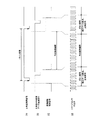
図7は可変ゲインアンプ213のゲインの設定を説明するためのタイミングチャートである。上記ステップS1009における可変ゲインアンプ213のゲインの設定は、(d)に示すように、有効画素出力領域以外のダミー出力(空転送部等)の領域で行う。ここでは、データの補正に、可変ゲインアンプ213のゲイン値を使用しているが、図4のアナログデジタル変換回路(AGC)215を通してデジタル画像信号としたところで、デジタル演算によりデータの補正を行ってもよい。
FIG. 7 is a timing chart for explaining the setting of the gain of the
また、電源ON直後は、電源ON時に生成された読取データを使用し、補正データを作成し、電源がOFFされるまでは、前回生成した補正データを使用するようにしてもよい。これにより、補正データが電源ON時に調整されたデータ、又は前回の最終補正データからスタートすることによって補正データを作成する時間を短縮することができる。 Immediately after the power is turned on, read data generated when the power is turned on is used to create correction data. Until the power is turned off, the correction data generated last time may be used. Thereby, the correction data can be shortened by starting from the data adjusted when the power is turned on, or the last final correction data.
更に、図示していないが画像読取装置の読取条件を設定する操作部によって、原稿の種類、サイズによって読取画像信号の補正を行うか行わないかを選択するようにしてもよい。これにより、A4サイズ原稿等、光量の短期変動が発生しないときには、通常の読取を行うようにもすることができる。 Further, although not shown, an operation unit for setting the reading condition of the image reading apparatus may select whether or not to correct the read image signal depending on the type and size of the document. As a result, when there is no short-term fluctuation in the amount of light, such as an A4 size document, normal reading can be performed.
上述した画像読取装置をスキャナ、複写機等の画像形成装置の読取手段に用いることにより、低コストで、高品質の画像読取が可能となる。また、この画像読取装置を使用することにより高画質の画像形成が可能な画像形成装置を提供することができる。 By using the above-described image reading apparatus as a reading unit of an image forming apparatus such as a scanner or a copying machine, high-quality image reading can be performed at low cost. In addition, an image forming apparatus capable of forming a high-quality image can be provided by using this image reading apparatus.
2 前方搬送ローラ対
4 第2基準白ローラ
5 第1基準白ローラ
6 第3基準白ローラ
8 後方搬送ローラ対
10 第2密着イメージセンサ(CIS)
11 第1密着イメージセンサ(CIS)
12 第3密着イメージセンサ(CIS)
21 第1信号処理部(AFE1)
22 第2信号処理部(AFE2)
23 第3信号処理部(AFE3)
24 信号処理及びメモリ部
25 タイミング制御及びメモリ部
31、32,33 第1、第2、第3光源
213 可変ゲインアンプ(VGA)
214 アナログデジタル変換回路(ADC)
2 Front
11 First contact image sensor (CIS)
12 Third image sensor (CIS)
21 1st signal processing part (AFE1)
22 Second signal processing unit (AFE2)
23 Third signal processing unit (AFE3)
24 Signal Processing and
214 Analog-to-digital converter (ADC)
Claims (8)
前記イメージセンサの原稿読取範囲外であって有効読取範囲内に設定された補正データ作成範囲で読み取られる白基準部における原稿の読取開始時の読取データと、原稿読取時の読取データとから前記個々のイメージセンサ毎に補正データを作成し、この補正データに基づいて読取画像信号を補正する手段を備えていることを特徴とする画像読取装置。 Use multiple image sensors smaller than the maximum reading width and multiple light sources that illuminate the document, and stagger the individual image sensors and the end including the effective pixel range of the light sources to overlap, and output from each image sensor. In an image reading device that stitches together and reads large format documents,
From the read data at the start of reading of the original in the white reference portion, which is read within the correction data creation range set outside the original reading range of the image sensor and within the effective reading range, and the individual read data from the read data at the time of reading the original An image reading apparatus comprising means for generating correction data for each image sensor and correcting a read image signal based on the correction data.
前記補正データは、前記補正データ範囲の1ライン中の予め設定された特定の領域の平均した値であることを特徴とする画像読取装置。 The image reading apparatus according to claim 1.
The image reading apparatus according to claim 1, wherein the correction data is an average value of a specific area set in advance in one line of the correction data range.
前記補正データに使用する補正データ範囲は、1ライン中の全範囲の領域の平均した値であることを特徴とする画像読取装置。 The image reading apparatus according to claim 1.
The correction data range used for the correction data is an average value of the entire range in one line.
前記補正データは、補正データ範囲の副走査の複数ライン分の単純平均値であることを特徴とする画像読取装置。 The image reading apparatus according to claim 1.
The image reading apparatus according to claim 1, wherein the correction data is a simple average value for a plurality of sub-scanning lines in the correction data range.
前記補正データは、補正データ範囲の副走査の複数ライン分の重加算平均した値であることを特徴とする画像読取装置。 The image reading apparatus according to claim 1.
The image reading apparatus according to claim 1, wherein the correction data is a value obtained by averaging the multiple additions for a plurality of sub-scans in the correction data range.
前記補正データは、前記イメージセンサの一端又は両端の補正データ作成範囲を使って作成することを特徴とする画像読取装置。 The image reading apparatus according to any one of claims 1 to 5,
The image reading apparatus, wherein the correction data is created using a correction data creation range at one or both ends of the image sensor.
電源投入直後は、電源投入時に生成された読取データを使用して補正データを作成し、電源が切られるまでは、前回生成した補正データを使用することを特徴とする画像読取装置。 The image reading apparatus according to any one of claims 1 to 6,
Immediately after the power is turned on, the correction data is created using the read data generated when the power is turned on, and the previously generated correction data is used until the power is turned off.
Priority Applications (1)
| Application Number | Priority Date | Filing Date | Title |
|---|---|---|---|
| JP2007167827A JP2009010507A (en) | 2007-06-26 | 2007-06-26 | Image reading apparatus and image forming apparatus |
Applications Claiming Priority (1)
| Application Number | Priority Date | Filing Date | Title |
|---|---|---|---|
| JP2007167827A JP2009010507A (en) | 2007-06-26 | 2007-06-26 | Image reading apparatus and image forming apparatus |
Publications (1)
| Publication Number | Publication Date |
|---|---|
| JP2009010507A true JP2009010507A (en) | 2009-01-15 |
Family
ID=40325177
Family Applications (1)
| Application Number | Title | Priority Date | Filing Date |
|---|---|---|---|
| JP2007167827A Pending JP2009010507A (en) | 2007-06-26 | 2007-06-26 | Image reading apparatus and image forming apparatus |
Country Status (1)
| Country | Link |
|---|---|
| JP (1) | JP2009010507A (en) |
Cited By (3)
| Publication number | Priority date | Publication date | Assignee | Title |
|---|---|---|---|---|
| JP2014033285A (en) * | 2012-08-01 | 2014-02-20 | Katsuragawa Electric Co Ltd | Document reading device |
| JP2015076748A (en) * | 2013-10-09 | 2015-04-20 | 富士ゼロックス株式会社 | Image reading device, image reading program, and image forming apparatus |
| WO2018190165A1 (en) * | 2017-04-13 | 2018-10-18 | 理想科学工業株式会社 | Image reader for image printed on web |
-
2007
- 2007-06-26 JP JP2007167827A patent/JP2009010507A/en active Pending
Cited By (4)
| Publication number | Priority date | Publication date | Assignee | Title |
|---|---|---|---|---|
| JP2014033285A (en) * | 2012-08-01 | 2014-02-20 | Katsuragawa Electric Co Ltd | Document reading device |
| JP2015076748A (en) * | 2013-10-09 | 2015-04-20 | 富士ゼロックス株式会社 | Image reading device, image reading program, and image forming apparatus |
| WO2018190165A1 (en) * | 2017-04-13 | 2018-10-18 | 理想科学工業株式会社 | Image reader for image printed on web |
| JP2018182529A (en) * | 2017-04-13 | 2018-11-15 | 理想科学工業株式会社 | Image reader |
Similar Documents
| Publication | Publication Date | Title |
|---|---|---|
| US7688488B2 (en) | Image reading device and image forming apparatus including the same | |
| JP5652063B2 (en) | Image reading apparatus, image forming apparatus, and shading correction method | |
| JP6512744B2 (en) | Image reader | |
| JP2009010507A (en) | Image reading apparatus and image forming apparatus | |
| JP2015119388A (en) | Image reading device, image forming apparatus, image reading method, and program | |
| JP5481435B2 (en) | Image reading apparatus and image forming apparatus | |
| JP6354328B2 (en) | Image reading apparatus, image forming apparatus, and image reading method | |
| JP6044126B2 (en) | Image reading apparatus, image forming apparatus, gain adjustment method and program | |
| JP6303504B2 (en) | Photoelectric conversion element, image reading apparatus, and image forming apparatus | |
| JPH10145556A (en) | Image reader | |
| JP2018006890A (en) | Image reader and image forming apparatus | |
| JPH1042157A (en) | Image processing method and apparatus | |
| JP2007208878A (en) | Image reading device | |
| JP3768459B2 (en) | Image reading apparatus and image processing apparatus | |
| JP4127603B2 (en) | Image reading apparatus, image forming apparatus, and read image data processing method | |
| JP5387969B2 (en) | Image reading apparatus, image forming apparatus, and image reading method | |
| JP5298928B2 (en) | Image reading apparatus, image forming apparatus, and image reading method | |
| JP4989121B2 (en) | Image reading device | |
| JP2001331073A5 (en) | ||
| JP2007166207A (en) | Original reader | |
| JP2006245739A (en) | Image reading apparatus and image reading method | |
| JP2008028662A (en) | Image reading apparatus and image forming apparatus | |
| JP2008244900A (en) | Image reader and image forming apparatus | |
| JP6287630B2 (en) | Image reading apparatus, image forming apparatus, and image reading method | |
| JP2008017431A (en) | Image reading apparatus and image forming apparatus |