JP2009012149A - Power tool - Google Patents
Power tool Download PDFInfo
- Publication number
- JP2009012149A JP2009012149A JP2007179253A JP2007179253A JP2009012149A JP 2009012149 A JP2009012149 A JP 2009012149A JP 2007179253 A JP2007179253 A JP 2007179253A JP 2007179253 A JP2007179253 A JP 2007179253A JP 2009012149 A JP2009012149 A JP 2009012149A
- Authority
- JP
- Japan
- Prior art keywords
- power
- power supply
- motor
- power source
- control
- Prior art date
- Legal status (The legal status is an assumption and is not a legal conclusion. Google has not performed a legal analysis and makes no representation as to the accuracy of the status listed.)
- Pending
Links
- 238000001514 detection method Methods 0.000 description 11
- 239000003990 capacitor Substances 0.000 description 5
- 238000010586 diagram Methods 0.000 description 5
- 238000013459 approach Methods 0.000 description 1
- 230000002457 bidirectional effect Effects 0.000 description 1
- 238000006243 chemical reaction Methods 0.000 description 1
- 230000007423 decrease Effects 0.000 description 1
- 238000000034 method Methods 0.000 description 1
Images


Classifications
-
- H—ELECTRICITY
- H02—GENERATION; CONVERSION OR DISTRIBUTION OF ELECTRIC POWER
- H02H—EMERGENCY PROTECTIVE CIRCUIT ARRANGEMENTS
- H02H11/00—Emergency protective circuit arrangements for preventing the switching-on in case an undesired electric working condition might result
-
- H—ELECTRICITY
- H02—GENERATION; CONVERSION OR DISTRIBUTION OF ELECTRIC POWER
- H02H—EMERGENCY PROTECTIVE CIRCUIT ARRANGEMENTS
- H02H7/00—Emergency protective circuit arrangements specially adapted for specific types of electric machines or apparatus or for sectionalised protection of cable or line systems, and effecting automatic switching in the event of an undesired change from normal working conditions
- H02H7/08—Emergency protective circuit arrangements specially adapted for specific types of electric machines or apparatus or for sectionalised protection of cable or line systems, and effecting automatic switching in the event of an undesired change from normal working conditions for dynamo-electric motors
- H02H7/0833—Emergency protective circuit arrangements specially adapted for specific types of electric machines or apparatus or for sectionalised protection of cable or line systems, and effecting automatic switching in the event of an undesired change from normal working conditions for dynamo-electric motors for electric motors with control arrangements
Landscapes
- Control Of Ac Motors In General (AREA)
- Control Of Direct Current Motors (AREA)
- Control Of Electric Motors In General (AREA)
- Portable Power Tools In General (AREA)
Abstract
Description
本発明は、電源コードの先端のプラグをコンセントに接続することにより得られた交流電力を位相制御により調整してモータに供給し、前記モータの回転速度制御を行なう構成の電動工具に関する。 The present invention relates to an electric tool having a configuration in which AC power obtained by connecting a plug at the end of a power cord to an outlet is adjusted by phase control and supplied to a motor to control the rotational speed of the motor.
商用周波数の交流電源に接続されたモータの回転速度を制御する技術が特許文献1に記載されている。
特許文献1に記載されたモータの回転速度制御手段は、図4に示すように、制御部、補正部、信号変換部から構成されており、モータの速度検出手段と回転速度設定手段との偏差Eが減少するようにスイッチング素子を動作させて、モータの回転速度を制御する。即ち、モータの回転速度制御手段は、スイッチング素子をオンさせるタイミングを交流電圧の位相に応じて変化させることで、モータに対する電力供給時間を調整し、モータの回転速度を制御する(位相制御)。前記モータの回転速度制御手段は交流用の電動工具の制御回路にも一般的に使用されている。
Patent Document 1 discloses a technique for controlling the rotation speed of a motor connected to a commercial frequency AC power source.
As shown in FIG. 4, the rotational speed control means of the motor described in Patent Document 1 includes a control unit, a correction unit, and a signal conversion unit, and the deviation between the motor speed detection means and the rotational speed setting means. The switching element is operated so that E decreases, and the rotational speed of the motor is controlled. That is, the rotation speed control means of the motor adjusts the power supply time to the motor and controls the rotation speed of the motor by changing the timing for turning on the switching element according to the phase of the AC voltage (phase control). The rotation speed control means of the motor is generally used in a control circuit for an AC power tool.
交流用の電動工具は電源コードを備えており、その電源コードの先端に取り付けられたプラグをコンセントに差し込んだ状態で使用する。ここで、電動工具のプラグは、AC用コンセントの形状に合わせて形成されているため、通常、直流電源等のコンセントに接続することはできない。しかし、外国の一部のエンジン付溶接機では、AC用コンセントの形状と等しい形状の直流電源用(DC用)コンセントを備えているものがある。このため、前記電動工具のプラグを誤ってDC用コンセントに接続して使用することも考えられる。
上記したモータの回転速度制御手段を備える電動工具を直流電源に接続した場合、電圧が一定であるためスイッチング素子が一旦オンするとオフしなくなり、モータには常に最大電力が供給される。このため、モータが常に全速駆動となって、モータの回転速度制御が行われなくなる。
The power tool for AC is provided with a power cord, and the plug attached to the tip of the power cord is inserted into an outlet. Here, since the plug of the electric power tool is formed in accordance with the shape of the AC outlet, it cannot normally be connected to an outlet such as a DC power source. However, some foreign welders with an engine have a DC power outlet (DC) outlet having a shape equal to that of an AC outlet. For this reason, it is also conceivable to use the power tool plug by mistakenly connecting it to a DC outlet.
When the electric tool provided with the motor rotation speed control means described above is connected to a DC power source, the voltage is constant, so that once the switching element is turned on, it is not turned off, and the maximum power is always supplied to the motor. For this reason, the motor is always driven at full speed, and the rotational speed control of the motor is not performed.
本発明は、上記問題点を解決するためになされたものであり、本発明が解決しようとする課題は、電動工具のプラグを誤って直流電源コンセントに接続した場合でも、モータが動作しないようにすることである。 The present invention has been made to solve the above problems, and the problem to be solved by the present invention is to prevent the motor from operating even when the plug of the electric power tool is mistakenly connected to the DC power outlet. It is to be.
上記した課題は、各請求項の発明によって解決される。
請求項1の発明は、電源コードの先端のプラグをコンセントに接続することにより得られた交流電力を位相制御により調整してモータに供給し、前記モータの回転速度制御を行なう構成の電動工具であって、交流電力の位相制御を行なう位相制御手段と、前記位相制御手段を動作させるための電力を供給する電力供給手段と、前記プラグが接続された前記コンセントの電源が交流電源か直流電源かを判定する電源判定手段とを有し、前記電源判定手段は、前記コンセントの電源が直流電源と判定した場合に、前記電力供給手段が前記位相制御手段に供給する電力を遮断するように、その電力供給手段に対してオフ信号を出力し、前記コンセントの電源が交流電源と判定した場合に、電力供給手段が前記位相制御手段に電力を供給するように、その電力供給手段に対してオン信号を出力することを特徴とする。
The above-described problems are solved by the inventions of the claims.
The invention according to claim 1 is an electric tool configured to adjust the AC power obtained by connecting the plug at the tip of the power cord to an outlet and to supply it to the motor by phase control, and to control the rotational speed of the motor. Phase control means for performing phase control of AC power, power supply means for supplying power for operating the phase control means, and whether the power source of the outlet connected to the plug is an AC power supply or a DC power supply. Power determining means for determining the power supply means so that the power supply means cuts off the power supplied to the phase control means when the power supply of the outlet is determined to be a DC power supply. When an off signal is output to the power supply means and the power source of the outlet is determined to be an AC power supply, the power supply means supplies power to the phase control means. And outputs an ON signal to the power supply unit.
本発明によると、プラグが接続されたコンセントの電源が交流電源か直流電源かを判定する電源判定手段を有している。そして、電源判定手段は、コンセントの電源が直流電源と判定した場合に、電力供給手段が位相制御手段に供給する電力を遮断するように、その電力供給手段に対してオフ信号を出力する。即ち、プラグが直流電源に接続された場合には、電力供給手段が位相制御手段に電力を供給しないため、位相制御手段は動作しなくなる。このため、モータが回転することはなく、従来のように、モータが起動した状態で回転制御不能になるような不具合が生じない。
なお、電源判定手段は、コンセントの電源が交流電源と判定した場合には、電力供給手段が前記位相制御手段に電力を供給するように、その電力供給手段に対してオン信号を出力する。このため、位相制御手段が動作可能になり、通常どおりモータに供給する交流電力を調整できるようになる。
According to the present invention, the power supply determining means for determining whether the power supply of the outlet connected to the plug is an AC power supply or a DC power supply is provided. Then, when the power source determination unit determines that the power source of the outlet is a DC power source, the power supply unit outputs an off signal to the power supply unit so as to cut off the power supplied to the phase control unit. That is, when the plug is connected to a DC power source, the power supply means does not supply power to the phase control means, and therefore the phase control means does not operate. For this reason, the motor does not rotate, and there is no problem that rotation control becomes impossible when the motor is activated as in the prior art.
When the power source determining unit determines that the power source of the outlet is an AC power source, the power determining unit outputs an ON signal to the power supplying unit so that the power supplying unit supplies power to the phase control unit. For this reason, the phase control means becomes operable, and the AC power supplied to the motor can be adjusted as usual.
請求項2の発明によると、電源判定手段は、電源の電圧波形に基づいて交流電源か直流電源かを判定することを特徴とする。 According to a second aspect of the present invention, the power source determining means determines whether the power source is an AC power source or a DC power source based on a voltage waveform of the power source.
本発明によると、電動工具のプラグを誤って直流電源コンセントに接続した場合でも、モータが動作しない。 According to the present invention, even if the plug of the electric tool is mistakenly connected to the DC power outlet, the motor does not operate.
(実施形態1)
以下、図1から図3に基づいて、本発明の実施形態1に係る電動工具の説明を行なう。本実施形態に係る電動工具は、交流電力を位相制御により調整してモータの回転速度制御を行なう構成の電動工具である。ここで、図1は本実施形態に係る電動工具の信号ブロック図、図2は電動工具の模式回路図である。また、図3は電動工具の動作を表すフローチャートである。
(Embodiment 1)
Hereinafter, the power tool according to the first embodiment of the present invention will be described with reference to FIGS. 1 to 3. The power tool according to the present embodiment is a power tool configured to control the rotational speed of a motor by adjusting AC power by phase control. Here, FIG. 1 is a signal block diagram of the electric power tool according to the present embodiment, and FIG. 2 is a schematic circuit diagram of the electric power tool. FIG. 3 is a flowchart showing the operation of the power tool.
<電動工具の基本回路構成について>
電動工具は、交流用であり、図1、図2に示すように、モータMと、モータ制御用IC10と、双方向サイリスタ(トライアック)等からなる駆動部15とを備えている。モータ制御用IC10は、回転速度設定部11からの速度設定信号n0に基づいてモータMの回転速度nが速度設定信号n0に近づくように、駆動部15を駆動させる。即ち、モータ制御用IC10は、速度設定信号n0とモータMの回転速度nとの偏差が減少するように駆動部15のトライアックに対してトリガパルスを出力し、前記トライアックをオンさせるタイミングを交流電圧の位相に応じて変化させる。これにより、モータMに電力が供給される時間が調整され、モータMの回転速度が制御される。なお、図2における符号MsはモータMの回転速度検知器である。
即ち、モータ制御用IC10、及び駆動部15が本発明の位相制御手段に相当する。
また、電動工具は、モータ制御用IC10に対する電力の供給、あるいは電力の遮断を行なうためのモータ制御用IC電源部5、モータ制御用IC電源駆動部4、制御部2、AC/DC電圧検出部3を備えている。
<About the basic circuit configuration of the power tool>
The electric power tool is for AC use, and includes a motor M, a
That is, the
In addition, the power tool includes a motor control IC
<AC/DC電圧検出部3、制御部2について>
AC/DC電圧検出部3、制御部2は、図2に示すように、電動工具の電源コード(図示省略)先端のプラグPa,Pbが電源コンセントCa、Cbに差し込まれた状態で、そのコンセントCa,Cbの電源が交流電源か直流電源かを判定する部分である。AC/DC電圧検出部3は、制御部2の入力端子と電源ラインCb,Pbとを抵抗を介して接続する部材であり、制御部2の入力端子に電源の電圧波形を導けるように構成されている。
制御部2は、制御用電源6から電力の供給を受けて動作するマイコンであり、AC/DC電圧検出部3を介して入力された電圧波形から交流電源か直流電源かを判定する。即ち、電圧波形がパルス状に変化すれば交流であり、電圧波形がほぼ一定の場合には直流と判定される。
制御部2は、交流電源と判定した場合にはモータ制御用IC電源駆動部4に対してオン信号(0信号)を出力し、直流電源と判定した場合にはモータ制御用IC電源駆動部4に対してオフ信号(+V信号)を出力する。
即ち、AC/DC電圧検出部3、制御部2が本発明の電源判定手段に相当する。
<About AC / DC voltage detection unit 3 and
As shown in FIG. 2, the AC / DC voltage detection unit 3 and the
The
The
That is, the AC / DC voltage detection unit 3 and the
<モータ制御用IC電源部5、モータ制御用IC電源駆動部4について>
モータ制御用IC電源部5は、モータ制御用IC10に対して一定の直流電圧が加わるように構成された電源部であり、直列に接続されたコンデンサ5c、抵抗5r、及びダイオード5dとを備えている、そして、前記コンデンサ5cの端子にモータ制御用IC10の電源端子P,Nが並列接続されている。なお、モータ制御用IC10の電源端子のN側はアースEに接続されている。
モータ制御用IC電源駆動部4は、制御部2からの出力信号を受けて、モータ制御用IC電源部5をオン/オフする部分であり、モータ制御用IC電源部5のコンデンサ5cと並列に接続されたトランジスタ4tを備えている。そして、前記トランジスタ4tのベース端子(入力端子)に、制御部2からの出力信号が入力されるように構成されている。
即ち、制御部2が交流電源と判定してオン信号(0信号)を出力すると、モータ制御用IC電源駆動部4のトランジスタ4tが導通せず(オフ状態)、モータ制御用IC電源部5のコンデンサ5cの端子、及びモータ制御用IC10の電源端子には一定電圧が加わるようになる。即ち、モータ制御用IC10に対して電力の供給が継続される。
また、制御部2が直流電源と判定してオフ信号(+V信号)を出力すると、プラグのPa端子がプラス側(+)、Pb端子がマイナス側(−)に接続されている場合に、モータ制御用IC電源駆動部4のトランジスタ4tが導通する(オン状態)。これにより、モータ制御用IC電源部5のコンデンサ5cの端子間、及びモータ制御用IC10の電源端子P,N間に加わる電圧が0Vとなり、モータ制御用IC10に対して電力の供給が遮断される。
なお、プラグのPa端子がマイナス側(−)、Pb端子がプラス側(+)に接続された場合にも、モータ制御用IC10の電源端子P,Nに加わる電圧は0Vとなるため、モータ制御用IC10に対して電力の供給が遮断される。
即ち、前記モータ制御用IC電源部5、モータ制御用IC電源駆動部4が本発明の電力供給手段に相当する。
<Regarding Motor Control IC Power Supply 5 and Motor Control IC Power Supply Drive 4>
The motor control IC
The motor control IC power supply drive unit 4 is a part that receives the output signal from the
That is, when the
Further, when the
Even when the plug's Pa terminal is connected to the negative side (-) and the Pb terminal is connected to the positive side (+), the voltage applied to the power supply terminals P and N of the
That is, the motor control IC
<電動工具の動作について>
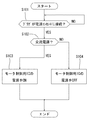
次に、図3に基づいて本実施形態に係る電動工具の動作について説明する。
電動工具の電源コードのプラグPa,Pbが電源コンセントCa,Cbに接続されると(ステップS101 YES)、AC/DC電圧検出部3、制御部2により、そのコンセントCa,Cbの電源が交流電源か、あるいは直流電源かが判定される。コンセントCa,Cbの電源が直流電源の場合には(ステップS102 NO)、制御部2がモータ制御用IC電源駆動部4に対してオフ信号(+V信号)を出力する。これにより、モータ制御用IC電源駆動部4のトランジスタ4tが導通して、モータ制御用IC10に対する電力の供給が遮断される(ステップS104)。この結果、モータ制御用IC10が動作せず、モータMは回転しない。
また、コンセントCa,Cbの電源が交流電源の場合には(ステップS102 YES)、制御部2がモータ制御用IC電源駆動部4に対してオン信号(0信号)を出力する。これにより、モータ制御用IC電源駆動部4のトランジスタ4tが導通しないため、モータ制御用IC10に対して電力の供給が継続される(ステップS103)。この結果、モータ制御用IC10及び駆動部15が動作可能となり、モータMに供給される交流電力が調整されて回転速度制御が行なわれる。
<About the operation of the power tool>
Next, operation | movement of the electric tool which concerns on this embodiment is demonstrated based on FIG.
When the plugs Pa and Pb of the power cord of the electric tool are connected to the power outlets Ca and Cb (YES in step S101), the AC / DC voltage detection unit 3 and the
When the power sources of the outlets Ca and Cb are AC power sources (YES in step S102), the
<本実施形態に係る電動工具の長所について>
本実施形態に係る電動工具によると、プラグPa、Pbが接続されたコンセントCa,Cbの電源が交流電源か直流電源かを判定する電源判定手段(AC/DC電圧検出部3、制御部2)を有している。そして、電源判定手段は、コンセントCa,Cbの電源が直流電源と判定した場合に、電力供給手段(モータ制御用IC電源部5、モータ制御用IC電源駆動部4)がモータ制御用IC10に供給する電力を遮断するように、その電力供給手段に対してオフ信号を出力する。即ち、プラグPa、Pbが直流電源に接続された場合には、電力供給手段がモータ制御用IC10に電力を供給しないため、モータ制御用IC10は動作しなくなる。このため、モータMが回転することはなく、従来のように、モータMが起動した状態で回転制御不能になるような不具合が生じない。
なお、電源判定手段(AC/DC電圧検出部3、制御部2)は、コンセントCa,Cbの電源が交流電源と判定した場合には、電力供給手段(モータ制御用IC電源部5、モータ制御用IC電源駆動部4)がモータ制御用IC10に電力を供給するように、その電力供給手段に対してオン信号を出力する。このため、モータ制御用IC10が動作可能になり、通常どおりモータMに供給する交流電力を調整できるようになる。
<Advantages of the electric power tool according to this embodiment>
According to the electric power tool according to the present embodiment, the power source determination means (AC / DC voltage detection unit 3, control unit 2) that determines whether the power source of the outlets Ca and Cb to which the plugs Pa and Pb are connected is an AC power source or a DC power source. have. The power supply determining means supplies power to the
The power source determination means (AC / DC voltage detection unit 3, control unit 2), when the power source of the outlets Ca and Cb is determined to be an AC power source, the power supply unit (motor control IC
<変更例>
ここで、本発明は上記実施形態に限定されるものではなく、本発明の要旨を逸脱しない範囲における変更が可能である。例えば、本実施形態では、モータ制御用IC10と制御部2、AC/DC電圧検出部3とを別々に設ける例を示したが、モータ制御用IC10に制御部2の機能を兼用させることも可能である。
<Example of change>
Here, the present invention is not limited to the above-described embodiment, and can be modified without departing from the gist of the present invention. For example, in the present embodiment, an example in which the
M・・・・・・モータ
Pa,Pb・・プラグ
Ca,Cb・・コンセント
2・・・・・・制御部(電源判定手段)
3・・・・・・AC/DC電圧検出部(電源判定手段)
4・・・・・・モータ制御IC電源駆動部(電源供給手段)
5・・・・・・モータ制御IC電源部(電源供給手段)
10・・・・・モータ制御用IC(位相制御手段)
15・・・・・駆動部(位相制御手段)
M ······ Motor Pa, Pb ··· Plug Ca, Cb ···
3 .... AC / DC voltage detector (power source judging means)
4 .... Motor control IC power supply drive (power supply means)
5 .... Motor control IC power supply (power supply means)
10 ... IC for motor control (phase control means)
15... Drive unit (phase control means)
Claims (2)
交流電力の位相制御を行う位相制御手段と、
前記位相制御手段を動作させるための電力を供給する電力供給手段と、
前記プラグが接続された前記コンセントの電源が交流電源か直流電源かを判定する電源判定手段とを有し、
前記電源判定手段は、前記コンセントの電源が直流電源と判定した場合に、前記電力供給手段が前記位相制御手段に供給する電力を遮断するように、その電力供給手段に対してオフ信号を出力し、前記コンセントの電源が交流電源と判定した場合に、電力供給手段が前記位相制御手段に電力を供給するように、その電力供給手段に対してオン信号を出力することを特徴とする電動工具。 An electric tool configured to adjust the AC power obtained by connecting the plug at the end of the power cord to an outlet by phase control and to supply the motor, and to control the rotational speed of the motor,
Phase control means for performing phase control of AC power;
Power supply means for supplying power for operating the phase control means;
Power determining means for determining whether the power source of the outlet to which the plug is connected is an AC power source or a DC power source,
The power supply determination means outputs an off signal to the power supply means so that the power supply means cuts off the power supplied to the phase control means when the power supply of the outlet is determined to be a DC power supply. When the power source of the outlet is determined to be an AC power source, the power tool outputs an ON signal to the power supply means so that the power supply means supplies power to the phase control means.
前記電源判定手段は、電源の電圧波形に基づいて交流電源か直流電源かを判定することを特徴とする電動工具。
The electric tool according to claim 1,
The power source determining means determines whether the power source is an AC power source or a DC power source based on a voltage waveform of the power source.
Priority Applications (3)
| Application Number | Priority Date | Filing Date | Title |
|---|---|---|---|
| JP2007179253A JP2009012149A (en) | 2007-07-09 | 2007-07-09 | Power tool |
| CA002636870A CA2636870A1 (en) | 2007-07-09 | 2008-07-07 | Power tools |
| US12/216,577 US8217610B2 (en) | 2007-07-09 | 2008-07-08 | Power tools |
Applications Claiming Priority (1)
| Application Number | Priority Date | Filing Date | Title |
|---|---|---|---|
| JP2007179253A JP2009012149A (en) | 2007-07-09 | 2007-07-09 | Power tool |
Publications (1)
| Publication Number | Publication Date |
|---|---|
| JP2009012149A true JP2009012149A (en) | 2009-01-22 |
Family
ID=40224440
Family Applications (1)
| Application Number | Title | Priority Date | Filing Date |
|---|---|---|---|
| JP2007179253A Pending JP2009012149A (en) | 2007-07-09 | 2007-07-09 | Power tool |
Country Status (3)
| Country | Link |
|---|---|
| US (1) | US8217610B2 (en) |
| JP (1) | JP2009012149A (en) |
| CA (1) | CA2636870A1 (en) |
Cited By (5)
| Publication number | Priority date | Publication date | Assignee | Title |
|---|---|---|---|---|
| JP2009296818A (en) * | 2008-06-06 | 2009-12-17 | Yokogawa Electric Corp | Protection circuit |
| WO2011099506A1 (en) | 2010-02-10 | 2011-08-18 | 前田金属工業株式会社 | Motorized tool |
| EP2386928A1 (en) | 2010-05-12 | 2011-11-16 | Maeda Metal Industries, Ltd. | Phase control apparatus |
| DE102022116451A1 (en) | 2021-07-06 | 2023-01-12 | Makita Corporation | TECHNIQUE FOR REMOVING HEAT IN AN ELECTRICAL WORKING MACHINE |
| JP2023008736A (en) * | 2021-07-06 | 2023-01-19 | 株式会社マキタ | electric work machine |
Families Citing this family (4)
| Publication number | Priority date | Publication date | Assignee | Title |
|---|---|---|---|---|
| JP5647048B2 (en) * | 2011-03-22 | 2014-12-24 | 株式会社マキタ | Electric tool |
| DE102012220482A1 (en) * | 2012-11-09 | 2014-05-15 | Wagner Vermögensverwaltungs-GmbH & Co. KG | Method for controlling a rotary screwdriver and screwdrivers |
| EP3296063B1 (en) | 2016-06-24 | 2020-03-25 | Black & Decker Inc. | Control scheme for power tool having a brushless motor |
| US12088222B2 (en) * | 2019-01-28 | 2024-09-10 | Ridge Tool Company | Soft start for power tool with momentary switch and mechanical direction selection switch |
Family Cites Families (15)
| Publication number | Priority date | Publication date | Assignee | Title |
|---|---|---|---|---|
| US5477133A (en) * | 1993-07-29 | 1995-12-19 | Etcon Corporation | Device for measuring a wide range of voltages and for determining continuity using visual and tactile indicators |
| US5444214A (en) * | 1993-12-06 | 1995-08-22 | The Lincoln Electric Company | Apparatus and method for synchronizing a firing circuit for a brushless alternator rectified D. C. welder |
| JPH08154392A (en) | 1994-11-29 | 1996-06-11 | Brother Ind Ltd | Motor control device |
| US5929597A (en) * | 1997-04-23 | 1999-07-27 | Fiskars Inc. | Portable electrical power system to supply direct current voltage |
| JP3886067B2 (en) * | 1997-05-15 | 2007-02-28 | 日本電産シバウラ株式会社 | Electric tool |
| US6222285B1 (en) * | 1999-09-07 | 2001-04-24 | Shop Vac Corporation | Intelligent switch control circuit |
| JP3673128B2 (en) * | 1999-11-16 | 2005-07-20 | 株式会社マキタ | Power tool with preset speed switch |
| US6765317B2 (en) * | 2002-04-02 | 2004-07-20 | Defond Manufacturing Limited | Power supply module for electrical power tools |
| JP2004261909A (en) * | 2003-02-28 | 2004-09-24 | Hitachi Koki Co Ltd | Electric tool |
| JP2007504800A (en) * | 2003-09-05 | 2007-03-01 | コニンクリユケ フィリップス エレクトロニクス エヌ.ブイ. | Power control device |
| JP2006052660A (en) * | 2004-08-10 | 2006-02-23 | Hitachi Koki Co Ltd | Air compressor and breaker operation prevention system using the same |
| US20090241283A1 (en) * | 2008-01-21 | 2009-10-01 | Michael Loveless | Tool operated switch for vacuums |
| US8476555B2 (en) * | 2008-08-29 | 2013-07-02 | Illinois Tool Works Inc. | Portable welding wire feed system and method |
| JP5418821B2 (en) * | 2009-07-13 | 2014-02-19 | 日立工機株式会社 | Electric tool |
| CN102082495B (en) * | 2009-12-01 | 2013-09-04 | 台达电子工业股份有限公司 | Power supply unit and power supply system with AC and DC voltage detection function |
-
2007
- 2007-07-09 JP JP2007179253A patent/JP2009012149A/en active Pending
-
2008
- 2008-07-07 CA CA002636870A patent/CA2636870A1/en not_active Abandoned
- 2008-07-08 US US12/216,577 patent/US8217610B2/en not_active Expired - Fee Related
Cited By (10)
| Publication number | Priority date | Publication date | Assignee | Title |
|---|---|---|---|---|
| JP2009296818A (en) * | 2008-06-06 | 2009-12-17 | Yokogawa Electric Corp | Protection circuit |
| WO2011099506A1 (en) | 2010-02-10 | 2011-08-18 | 前田金属工業株式会社 | Motorized tool |
| US8853987B2 (en) | 2010-02-10 | 2014-10-07 | Maeda Metal Industries, Ltd. | Electric tool |
| TWI490093B (en) * | 2010-02-10 | 2015-07-01 | Maeda Metal Ind | Electrical tools |
| EP2386928A1 (en) | 2010-05-12 | 2011-11-16 | Maeda Metal Industries, Ltd. | Phase control apparatus |
| US8547072B2 (en) | 2010-05-12 | 2013-10-01 | Maeda Metal Industries, Ltd. | Phase control apparatus |
| DE102022116451A1 (en) | 2021-07-06 | 2023-01-12 | Makita Corporation | TECHNIQUE FOR REMOVING HEAT IN AN ELECTRICAL WORKING MACHINE |
| JP2023008736A (en) * | 2021-07-06 | 2023-01-19 | 株式会社マキタ | electric work machine |
| JP7734538B2 (en) | 2021-07-06 | 2025-09-05 | 株式会社マキタ | electric work equipment |
| US12519376B2 (en) | 2021-07-06 | 2026-01-06 | Makita Corporation | Technique for dissipating heat in electric work machine |
Also Published As
| Publication number | Publication date |
|---|---|
| US20090015183A1 (en) | 2009-01-15 |
| US8217610B2 (en) | 2012-07-10 |
| CA2636870A1 (en) | 2009-01-09 |
Similar Documents
| Publication | Publication Date | Title |
|---|---|---|
| JP2009012149A (en) | Power tool | |
| US11533841B2 (en) | Electric working machine and method for controlling motor of electric working machine | |
| EP2915631B1 (en) | Electric tool | |
| US11161227B2 (en) | Electric working machine and method for controlling motor of electric working machine | |
| JP5824419B2 (en) | Electric tool | |
| US9077276B2 (en) | Motor control method and motor control apparatus for dental handpiece | |
| EP2164668B1 (en) | Welding power supply | |
| US20150158157A1 (en) | Electric power tool | |
| JP4193777B2 (en) | Power generation control device and power generation system | |
| CN101323038B (en) | Engine driven welding machine | |
| JP5891410B2 (en) | Electric tool | |
| US11211894B2 (en) | Electric tool | |
| CN111865145B (en) | Electric tool and control method thereof | |
| CN115733393A (en) | Electric working machine | |
| JP2013188825A (en) | Electric tool | |
| JP2009261146A (en) | Compressor controller | |
| JP5307997B2 (en) | Brushless DC motor drive device | |
| JP6092480B1 (en) | VEHICLE POWER SUPPLY SYSTEM AND CONTROL METHOD FOR VEHICLE POWER SUPPLY SYSTEM | |
| US20220087777A1 (en) | Dental treatment apparatus and method of driving the same | |
| JP4516698B2 (en) | Welding wire feed motor drive control device and inverter type arc welding machine | |
| JP2012157942A (en) | Electric power tool | |
| TWI297299B (en) | ||
| KR20130030676A (en) | Electronic power steering system | |
| KR20080107533A (en) | Power supply circuit of MDPS ECC and its control method | |
| KR100698476B1 (en) | Electric motor starting speed control device and method |