JP2009012902A - Paper feeding mechanism and paper feeding device for shredder - Google Patents
Paper feeding mechanism and paper feeding device for shredder Download PDFInfo
- Publication number
- JP2009012902A JP2009012902A JP2007174866A JP2007174866A JP2009012902A JP 2009012902 A JP2009012902 A JP 2009012902A JP 2007174866 A JP2007174866 A JP 2007174866A JP 2007174866 A JP2007174866 A JP 2007174866A JP 2009012902 A JP2009012902 A JP 2009012902A
- Authority
- JP
- Japan
- Prior art keywords
- paper
- bundle
- rotating
- shredder
- rotating body
- Prior art date
- Legal status (The legal status is an assumption and is not a legal conclusion. Google has not performed a legal analysis and makes no representation as to the accuracy of the status listed.)
- Pending
Links
- 210000000078 claw Anatomy 0.000 claims abstract description 50
- 230000002093 peripheral effect Effects 0.000 claims abstract description 17
- ZZUFCTLCJUWOSV-UHFFFAOYSA-N furosemide Chemical compound C1=C(Cl)C(S(=O)(=O)N)=CC(C(O)=O)=C1NCC1=CC=CO1 ZZUFCTLCJUWOSV-UHFFFAOYSA-N 0.000 abstract description 2
- 230000032258 transport Effects 0.000 description 11
- 238000000034 method Methods 0.000 description 3
- 238000009434 installation Methods 0.000 description 2
- 230000000694 effects Effects 0.000 description 1
- 238000012840 feeding operation Methods 0.000 description 1
- 230000007257 malfunction Effects 0.000 description 1
- 239000002184 metal Substances 0.000 description 1
- 238000003825 pressing Methods 0.000 description 1
- 238000000926 separation method Methods 0.000 description 1
- 229920003002 synthetic resin Polymers 0.000 description 1
- 239000000057 synthetic resin Substances 0.000 description 1
- 239000002699 waste material Substances 0.000 description 1
Images


Classifications
-
- B—PERFORMING OPERATIONS; TRANSPORTING
- B02—CRUSHING, PULVERISING, OR DISINTEGRATING; PREPARATORY TREATMENT OF GRAIN FOR MILLING
- B02C—CRUSHING, PULVERISING, OR DISINTEGRATING IN GENERAL; MILLING GRAIN
- B02C18/00—Disintegrating by knives or other cutting or tearing members which chop material into fragments
- B02C18/0007—Disintegrating by knives or other cutting or tearing members which chop material into fragments specially adapted for disintegrating documents
-
- B—PERFORMING OPERATIONS; TRANSPORTING
- B02—CRUSHING, PULVERISING, OR DISINTEGRATING; PREPARATORY TREATMENT OF GRAIN FOR MILLING
- B02C—CRUSHING, PULVERISING, OR DISINTEGRATING IN GENERAL; MILLING GRAIN
- B02C18/00—Disintegrating by knives or other cutting or tearing members which chop material into fragments
- B02C18/06—Disintegrating by knives or other cutting or tearing members which chop material into fragments with rotating knives
- B02C18/16—Details
- B02C18/22—Feed or discharge means
- B02C18/2225—Feed means
- B02C18/2283—Feed means using rollers
-
- B—PERFORMING OPERATIONS; TRANSPORTING
- B02—CRUSHING, PULVERISING, OR DISINTEGRATING; PREPARATORY TREATMENT OF GRAIN FOR MILLING
- B02C—CRUSHING, PULVERISING, OR DISINTEGRATING IN GENERAL; MILLING GRAIN
- B02C18/00—Disintegrating by knives or other cutting or tearing members which chop material into fragments
- B02C18/06—Disintegrating by knives or other cutting or tearing members which chop material into fragments with rotating knives
- B02C18/16—Details
- B02C2018/164—Prevention of jamming and/or overload
Landscapes
- Engineering & Computer Science (AREA)
- Food Science & Technology (AREA)
- Crushing And Pulverization Processes (AREA)
- Delivering By Means Of Belts And Rollers (AREA)
- Sheets, Magazines, And Separation Thereof (AREA)
Abstract
Description
本発明は、複数枚の紙束を送り出すことができる給紙機構と給紙装置に関し、特にツメ体を装備した第一回転体と第二回転体により複数枚の紙束に突き刺し、シュレッダーの処理可能な制限枚数の紙束を送出する給紙機構および給紙装置に関する。 The present invention relates to a paper feeding mechanism and a paper feeding device that can send out a plurality of paper bundles, and in particular, pierces a plurality of paper bundles by a first rotary body and a second rotary body equipped with a claw body, and processes a shredder The present invention relates to a paper feed mechanism and a paper feed device that send out a limited number of possible paper bundles.
近年情報の流出防止の観点から、書類をそのまま破棄せずにシュレッダー等の裁断機もしくは細断機により細かく裁断してから廃棄処理を行っている。
書類等を裁断するシュレッダーも近年では性能が上がり、再現が不可能となるようにより細かく裁断するものが増えている。しかしながら、一度に処理できる枚数は限られているという問題があった。廃棄処理する紙葉を一枚ずつ分離して裁断機に供給する機構は開発されているものの、シュレッダーが裁断できる処理可能な複数枚の紙束を適宜に送出して効率よく複数枚同時に裁断を行うことは、紙詰まりの問題が解決できないので簡単に実現できないという問題があった。
In recent years, from the viewpoint of preventing information leakage, documents are not discarded as they are, but are shredded by a shredder or other shredder or shredder and then discarded.
In recent years, shredders for cutting documents and the like have been improved in performance, and the number of shredders that are cut more finely so that they cannot be reproduced is increasing. However, there is a problem that the number of sheets that can be processed at a time is limited. Although a mechanism has been developed to separate the paper sheets to be discarded one by one and supply them to the cutting machine, multiple sheets that can be processed that can be cut by a shredder are sent out as needed to efficiently cut multiple sheets simultaneously. There is a problem that it cannot be easily realized because the paper jam problem cannot be solved.
上記問題を解決するために、複数枚の紙束を送出する「自動紙送り機構及び自動紙送り装置」(特願2006−145833)の機構が開発されている。この機構により、シュレッダーの処理能力に応じて制限枚数の紙束を強制的に送出しているが、鋭利部を備えた円盤状ツメ体の強制送出力が強く、制限枚数以上の紙束を送出して紙が楔状のスタック状態になって、ジャムとなり機能停止が発生する欠点が判明している。
そのため、スタックの原因となるシュレッダーの処理能力以上の紙束を供給しないように制限し、確実かつスムースにシュレッダーに制限枚数の紙束を送出する給紙機構および給紙装置の開発が待たれていた。
Therefore, development of a paper feeding mechanism and a paper feeding device that restricts the supply of paper bundles that exceed the processing capacity of the shredder that causes stacking and reliably and smoothly sends a limited number of paper bundles to the shredder is awaited. It was.
上記問題を解決するため、廃棄書類束をトレイにセットしておくだけで、ツメ体を装備した第一回転体および第二回転体により処理能力に応じた量の紙束が強制送出でき、シュレッダーの能力範囲内に制限された枚数の書類束を裁断させることができるシュレッダーの給紙機構および給紙装置を提供することを目的としている。 In order to solve the above problem, just by setting the waste document bundle on the tray, the first rotating body and the second rotating body equipped with the claw body can forcibly send the paper bundle in an amount corresponding to the processing capacity. It is an object of the present invention to provide a paper feeding mechanism and a paper feeding device for a shredder capable of cutting a bundle of documents limited in the capacity range.
本発明に係る給紙機構は、切断刃を噛合させて紙束を回転細断する細断部の回転駆動力を伝達利用して複数枚の紙束をシュレッダーに供給するシュレッダー装置の給紙機構であって、紙送り用の鋭利部が形成された円盤状ツメ体と回転部とを備えた第一回転体と、該第一回転体によって強制送出された紙束を送出する搬送ローラと、該搬送ローラによって送出された紙束の送出枚数を制限するとともにスタックした紙束を送出する鋭利部が形成された円盤状ツメ体と回転部とを備えた第二回転体と、該第二回転体の外周面と接触し紙束を挟持して送出する加圧ローラとを装備した構成である。 A paper feed mechanism according to the present invention is a paper feed mechanism of a shredder device that supplies a plurality of paper bundles to a shredder by transmitting a rotational driving force of a shredding section that meshes a cutting blade to rotate and shred a paper bundle. A first rotating body provided with a disk-shaped claw body formed with a sharp part for paper feeding and a rotating part, a conveying roller for sending a paper bundle forcibly sent by the first rotating body, A second rotating body including a disk-like claw body formed with a sharp portion for limiting the number of paper bundles fed by the conveying roller and feeding a stacked paper bundle, and a rotating portion; and the second rotation It is a configuration equipped with a pressure roller that comes into contact with the outer peripheral surface of the body and clamps and feeds the paper bundle.
また、前記円盤状ツメ体は、円盤状ツメ体の周縁に対して略垂直に鋭利部を形成した構成であり、または、円盤状ツメ体の外周縁に沿って鋭利部の先端が回転方向に向かって形成されている構成でもある。 Further, the disc-shaped claw body has a configuration in which a sharp portion is formed substantially perpendicular to the peripheral edge of the disc-shaped claw body, or the tip of the sharp portion in the rotation direction along the outer peripheral edge of the disc-shaped claw body. It is also the structure formed toward.
また、本発明の給紙装置は、切断刃を噛合させて紙束を回転細断する細断部の回転駆動力を伝達利用して複数枚の紙束をシュレッダーに供給するシュレッダー装置の給紙装置が、裁断する紙束をセットし保持する底面に孔を設けた給紙トレイと、紙送り用の鋭利部が形成された円盤状ツメ体と回転部とを備えた第一回転体と該第一回転体によって強制送出された紙束を送出する搬送ローラと該搬送ローラによって送出された紙束の送出枚数を制限するとともにスタックした紙束を送出する鋭利部が形成された円盤状ツメ体と回転部とを備えた第二回転体と該第二回転体の外周面と接触し紙束を挟持して送出する加圧ローラとからなる給紙機構と、駆動源からの動力を伝達するための第一回転体と搬送ローラと第二回転体の回転軸の端部に装備される少なくとも一つのギアと係合する複数のギア群からなるギア部とを装備した構成である。 Also, the paper feeding device of the present invention feeds a plurality of paper bundles to the shredder by transmitting the rotational driving force of the shredding part that meshes the cutting blades to rotate and shred the paper bundle. The apparatus includes a first rotating body including a paper feed tray provided with a hole in a bottom surface for setting and holding a bundle of paper to be cut, a disk-shaped claw body having a sharp portion for feeding paper, and a rotating portion, A disk-shaped claw body formed with a conveying roller for forcibly feeding a paper bundle forcibly delivered by the first rotating body, and a sharp portion for limiting the number of paper bundles delivered by the conveying roller and for delivering the stacked paper bundle A feed mechanism including a second rotating body having a rotating portion and a pressure roller that contacts the outer peripheral surface of the second rotating body and holds and feeds a bundle of paper, and transmits power from a drive source Equipped at the end of the rotating shaft of the first rotating body, transport roller and second rotating body Is a equipped with the structures and the gear portion of at least one gear and a plurality of gears to be engaged.
本発明に係る給紙装置および給紙方法は、上記詳述した通りの構成であるので、以下のような効果がある。
1.ツメ体を備えた回転体によって二段階で紙束を分離する構造であり、確実にシュレッダーの処理能力に応じた制限枚数の紙束を送出することができる。第二回転体と加圧ローラにより紙束を挟持し送出するためスタック状態の紙束を容易に引き出し、シュレッダー部へ安定した給紙を行うことができる。また、ツメ体を備えた第一回転体と第二回転体との間に搬送ローラが設けられているため、送出がスムースである。
Since the sheet feeding device and the sheet feeding method according to the present invention are configured as described in detail above, they have the following effects.
1. The paper bundle is separated in two stages by a rotating body provided with a claw body, and a limited number of paper bundles according to the processing capability of the shredder can be reliably sent out. Since the paper bundle is nipped and sent out by the second rotating body and the pressure roller, the stacked paper bundle can be easily pulled out, and the paper can be stably fed to the shredder portion. Moreover, since the conveyance roller is provided between the 1st rotary body provided with the nail | claw body and the 2nd rotary body, sending out is smooth.
2.紙束が回転体のローラ面に当接することにより、書類束をシュレッダーの制限枚数に分離することができる。鋭利部による突き刺しとローラ面への当接により紙様の枚数が制限され、スタックした紙束を強制送出することが可能で、シュレッダーに制限枚数以上の紙束を送出することを防ぐことができる。
3.ツメ体が回転方向に沿って形成されているため紙束に鋭利部を突き刺しやすく、確実に紙束に突き刺して紙を送り出すことができる。
4.シュレッダー部の駆動力を利用しているので、他の駆動装置を必要としないので効果的である。また、ギア構造により回転軸の回動を操作しやすく、効率よく紙束を送出することができる。
2. When the sheet bundle comes into contact with the roller surface of the rotating body, the document bundle can be separated into a limited number of shredders. The number of sheets of paper is limited by the piercing by the sharp part and the contact with the roller surface, it is possible to forcibly send out the stacked paper bundle, and it is possible to prevent the paper bundle exceeding the limited number from being sent to the shredder. .
3. Since the claw body is formed along the rotation direction, it is easy to pierce the sharp part into the paper bundle, and the paper can be reliably fed out into the paper bundle.
4). Since the driving force of the shredder portion is used, it is effective because no other driving device is required. Further, the gear structure makes it easy to operate the rotation of the rotation shaft, and the paper bundle can be sent out efficiently.
以下本発明にかかる給紙機構を図面に示す実施例に基づいて詳細に説明する。図1は本発明の給紙機構を備えた給紙装置の斜視図であり、図2は本発明の第一回転体および第二回転体の斜視図であり、図3は本発明の円盤状ツメ体の側面図であり、図4は別の円盤状ツメ体の側面図であり、図5は給紙機構におけるギアの係合構造の断面図である。
本発明の給紙機構11は、第一回転体20と、搬送ローラ30と、第二回転体40と、加圧ローラ60とからなる構成である。また、本発明の給紙装置10は、給紙機構11と、給紙トレイ70と、ギア部80とからなる構成である。
Hereinafter, a paper feed mechanism according to the present invention will be described in detail based on an embodiment shown in the drawings. FIG. 1 is a perspective view of a sheet feeding device provided with a sheet feeding mechanism of the present invention, FIG. 2 is a perspective view of a first rotating body and a second rotating body of the present invention, and FIG. 3 is a disk shape of the present invention. FIG. 4 is a side view of another claw-shaped claw body, and FIG. 5 is a cross-sectional view of a gear engagement structure in a paper feed mechanism.
The sheet feeding mechanism 11 of the present invention is configured by a first rotating
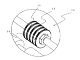
第一回転体20は、給紙トレイ70に積載された書類束からシュレッダーが裁断処理可能な枚数分の紙束72を分離し、強制的に送出する略円筒状の部材である。第一回転体20は、回転軸に固定された回転部22と円盤状ツメ体50とからなり、この実施例では二か所に第一回転体20を設けているが、第一回転体20の設置個所はこの実施例の設置個所に限定されず、一または複数個所に設けることができる。
回転部22は平滑な曲面を形成したローラ部材、または、図1に示すように周面にローレットまたは突部24を装備した円柱状部材とすることが可能である。
給紙トレイ70に積載された紙束72を上部から押圧し、回動自在に設置された第一回転体20によって、書類束上部の紙束72に鋭利先端が突き刺さって、刺さった分の紙束72が書類束上部から分離されて搬送ローラ30へ送出される。
The
The rotating
A paper bundle 72 loaded on the
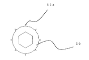
円盤状ツメ体50は周縁に鋭利部52a、52bを装備した円盤状の部材である。鋭利部52a、52bが紙束72に突き刺さり、貫通または突き刺した状態で紙束72を送出する。円盤状ツメ体50は回転部22の両端または一端に装備される。
円盤状ツメ体50の鋭利部52a、52bは、図3および図4に示すように円盤状ツメ体の外周に対し略垂直に形成した鋭利部52aや、円盤状ツメ体50の外周に外周縁に沿って鋭利部の先端が回転方向に向かって形成された鋭利部52b等からなり、紙束72を突き刺すことができる形状に形成されている。鋭利部52aは略垂直に形成しているため、どのような角度であっても紙束72を突き刺すことができ、紙束72が乱雑になっていても確実に一定量の紙束72を送り出すことができる。また、鋭利部52a、52bは、シュレッダーの裁断可能枚数に合わせて大きさを変更することが可能である。
The disk-
As shown in FIGS. 3 and 4, the sharp portions 52 a and 52 b of the disc-
図2に示すように、複数の回転部22と複数の円盤状ツメ体50を組み合わせた回転体とすることが可能である。回転部22の周面若しくは突部24に紙束72が当接することで、円盤状ツメ体50の鋭利部52a、52bによって突き刺した紙束72の枚数を制限する構成であり、円盤状ツメ体50周縁の高さから突き出した鋭利部52a、52bの鋭利部の長さによって送出する紙束72の量は自由に制御することが可能である。
As shown in FIG. 2, a rotating body in which a plurality of rotating
搬送ローラ30は、並行に設置された第一回転体20と第二回転体40との間に装備される紙束72を搬送するローラである。搬送ローラ30は上述のように一つから複数個並列して設けることができる。搬送ローラ30は、回転部22・42と同様に平滑面を形成した円柱部材や、周面に突部を形成した円柱部材とすることが可能である。
The
第二回転体40は、搬送ローラ30により搬送された複数枚の紙束72をシュレッダーの裁断処理能力に応じた制限枚数に分離して細断部に送出する。第二回転体40は図2に示す第一回転体20と同様に、回転部42と円盤状ツメ体50とからなり、回転部42は平滑な曲面を形成したローラ部材、または、ローレットや突部44を装備した円柱状部材とすることも可能である。
送出される紙束72は一枚の紙葉ではなく複数枚重なった紙束として送出する。なお、一枚でも送出可能である。枚数の調節は、回転部22、42、円盤状ツメ体50、または、鋭利部52a、52bの大きさ円周からの突出割合を変更することで対処することが可能である。また、第一回転体20と第二回転体40の回転部22、42および円盤状ツメ体50をそれぞれ異なる大きさにすることも可能である。第二回転体40の回転部42と、回転部42から突出した鋭利部52a、52bとの幅を第一回転体20より狭くすることで、用紙の分離機能をより確実にすることができる。
The second rotating
The paper bundle 72 to be sent out is not a single sheet of paper but is sent out as a stack of multiple sheets. Note that even one sheet can be sent out. The adjustment of the number of sheets can be dealt with by changing the protruding ratio of the rotating
加圧ローラ60は、図5に示すようにローラ面が第二回転体40の外周面と接触して回動することにより紙束72を送出する第一と第二の回転体の列とは対向する下側に設置されるローラである。加圧ローラ60の外周面は合成樹脂、金属で形成することも可能であるが、ゴム等の弾性体により形成されることが望ましい。弾性を有する外周面でツメ体を有する第二回転体40と上下から圧力を加えて紙束72を挟持し送出することにより、ゴムローラ同士、或いはゴムローラと剛性ローラによる組み合わせ以上の送出力と確実な送出作動を得ることができ、スタック状態の紙束72を容易に引き出すことが可能である。加圧ローラ60は外周面上の円盤状ツメ体の鋭利部52a、52bが接触する周面に、溝を設ける構造とすることができる。溝を設けることにより適度な挟持力を得ることができる。
As shown in FIG. 5, the pressure roller 60 has a roller surface that comes into contact with the outer peripheral surface of the second
次に、本発明の給紙装置10について詳述する。給紙装置10は、給紙機構11と、給紙トレイ70と、ギア部80とを備えた構成であり、本体と紙送出口とを備えるシュレッダー装置に組込むことにより、シュレッダー部の上に搭載して自動給紙装置として利用することが可能となる。この実施例では、シュレッダーの駆動源と同一の駆動源を利用することができるので、給紙装置に別に独立の駆動源を必要としない。
Next, the
給紙トレイ70は、第一回転体20により送出される紙束72の待機場所であり、書類束や複数枚の紙束がセットされる。第一回転体20の円盤状ツメ体50により送出される構成であるため、紙束72がセットされる角度としてはどのような角度でもよく、シュレッダー本体の上面と水平の給紙トレイとしてもよい。また、円盤状ツメ体50が確実に回転し、確実に紙束72を突き刺して送出できるように、給紙トレイ70の円盤状ツメ体の回動部位が通過する面には孔を形成することも可能である。円盤状ツメ体が紙束を突き刺して裏面に到達した場合、給紙トレイ70の底面を刺す事も考えられるが、給紙トレイに孔を形成することにより、少数枚の紙束であって鋭利部が裏面に到達しても給紙トレイを傷つけることなく、紙束を突き刺して送出することができる。
The
給紙機構11は、上述と同様に第一回転体20と、搬送ローラ30と、第二回転体40と、加圧ローラ60とからなる構成である。第一回転体20および第二回転体40は、回転部22・42と円盤状ツメ体50とからなる。
また、第一回転体20、搬送ローラ30、第二回転体40、および加圧ローラ60は、それぞれ並行に設けられた回転軸25・35・45・65に軸着されている。回転軸25・35・45・65は装置両側内部に渡って設けられる構成である。給紙装置側面に位置する回転軸の端部にギアを装備し、駆動源より発生した駆動力を回転軸に伝達する。また、回転軸に軸着された円盤状ツメ体50の鋭利部によって強制的に紙を送出する構造である。
給紙トレイ70にセットされた紙束72は、第一回転体20により紙束72の上面からシュレッダー部へ向かって送出される。紙束72は、第一回転体20の円盤状ツメ体50に形成された鋭利部に突き刺さって、搬送ローラ30へ送出され、搬送ローラ部で少数枚に制限される。さらに、第二段階として、搬送ローラ部に積載された紙束72が、第二回転体40による強制送出により順次送出される。
The paper feed mechanism 11 is configured by a first
Moreover, the 1st
The paper bundle 72 set in the
ギア部80は、図1で示すように駆動源からの駆動力を複数のギアを介して給紙機構に伝達するためのギア群である。ギア部80は、第一回転体20、搬送ローラ30、第二回転体40および加圧ローラ60が軸着された回転軸25・35・45・65の端部に装着される少なくとも一つのギアに係合し、駆動源の回転力を伝達する。残りの回転軸については、駆動力を伝達された回転軸とギアによって係合させ同時に回動する構造としている。また、給紙装置内部に装備されたローラの回転に伴い同時に回動する構造、また、ギアを有しない回動自由な回転軸に軸着された回転体が紙束の強制送出により同時に回動する構造とすることが可能である。
As shown in FIG. 1, the
図5に示す実施例では、第一回転体の回転軸25に設けられた第一ギア26と搬送ローラの回転軸35に設けられた第二ギア36を第三ギア82によって係合させ、回転軸25または回転軸35のどちらか一方をギア部によって回動させ、同時に他方の回転軸を回動する構造としている。また、第二回転体40はギア部80によって駆動する給紙装置内部の加圧ローラ60の回動とともに回動する構造としている。
また、回転軸25・35・45・65の端部に設けられたそれぞれのギアに係合し、各回転軸を回動させる構造とすることも可能である。
In the embodiment shown in FIG. 5, the
It is also possible to employ a structure that engages with the gears provided at the ends of the
本発明の給紙装置10は、紙を給紙トレイ70にセットし、シュレッダー部の動作を開始することにより、駆動力がギア部80に伝達され、ギアが装備された回転軸を回動させて第一回転体20と第二回転体40に装備される円盤状ツメ体50が回転して紙束72に鋭利部52a、52bが突き刺さり、強制的にシュレッダー部の方向に一定量以下の枚数の紙束72を送出する構成である。給紙装置10自体で駆動力を確保するために、駆動源を給紙装置に装備させることも可能である。また、送出される紙束72は一枚の紙葉であってもまた、一枚の紙葉ではない複数枚の紙束であっても、送出することが可能である。
The
上述したように、本発明の給紙機構および給紙装置は、第一回転体20と搬送ローラ30と第二回転体40とからなる送り機構により紙束72を送出する技術である。機器の処理能力に応じた給紙枚数の制限と、紙束の分離ならびに紙束の横幅の許容する形状を有する回転部22、42および鋭利部が形成された円盤状ツメ体50とを組み合わせて装備したものである。第一回転体および加圧ローラとともに紙束72を挟持し送出する第二回転体によって、二回にわたり紙束を突き刺し、2段階の強制送出を達成した構成と技術であるめ、確実にシュレッダーの裁断制限枚数の紙束を送出することができるとともに、安定して給紙を行うことが可能となった。
As described above, the paper feeding mechanism and the paper feeding device according to the present invention are techniques for feeding the paper bundle 72 by the feeding mechanism including the first
10 給紙装置
11 給紙機構
20 第一回転体
22、42 回転部
24、44 突部
25、35、45、65 回転軸
26 第一ギア
30 搬送ローラ
36 第二ギア
40 第二回転体
50 円盤状ツメ体
52a、52b 鋭利部
60 加圧ローラ
70 給紙トレイ
72 紙束
80 ギア部
82 第三ギア
DESCRIPTION OF
Claims (4)
紙送り用の鋭利部が形成された円盤状ツメ体と回転部とを備えた第一回転体と、該第一回転体によって強制送出された紙束を送出する搬送ローラと、該搬送ローラによって送出された紙束の送出枚数を制限するとともにスタックした紙束を送出する鋭利部が形成された円盤状ツメ体と回転部とを備えた第二回転体と、該第二回転体の外周面と接触し紙束を挟持して送出する加圧ローラと、を装備したことを特徴とする給紙機構。 In the paper feed mechanism of the shredder device that supplies a plurality of paper bundles to the shredder by transmitting the rotational driving force of the shredding part that rotates and shreds the paper bundle by meshing the cutting blade,
A first rotating body having a disk-shaped claw body formed with a sharp portion for feeding paper and a rotating section, a conveying roller for sending out a bundle of paper forcedly fed by the first rotating body, and the conveying roller A second rotating body including a disk-shaped claw body on which a sharp portion for limiting the number of fed paper bundles to be sent out and a stacked paper bundle is fed, and a rotating portion, and an outer peripheral surface of the second rotating body And a pressure roller that contacts and feeds the paper bundle.
裁断する紙束をセットし保持する底面に孔を設けた給紙トレイと、
紙送り用の鋭利部が形成された円盤状ツメ体と回転部とを備えた第一回転体と該第一回転体によって強制送出された紙束を送出する搬送ローラと該搬送ローラによって送出された紙束の送出枚数を制限するとともにスタックした紙束を送出する鋭利部が形成された円盤状ツメ体と回転部とを備えた第二回転体と該第二回転体の外周面と接触し紙束を挟持して送出する加圧ローラとからなる給紙機構と、
駆動源からの動力を伝達するための第一回転体と搬送ローラと第二回転体の回転軸の端部に装備される少なくとも一つのギアと係合する複数のギア群からなるギア部と、を装備することを特徴とする給紙装置。
A shredder paper feeding device that supplies a plurality of paper bundles to the shredder by transmitting the rotational driving force of the shredding part that rotates and shreds the paper bundle by engaging the cutting blade,
A paper feed tray with a hole in the bottom for setting and holding a bundle of paper to be cut;
A first rotating body provided with a disk-shaped claw body formed with a sharp part for feeding paper and a rotating part, a conveying roller for sending a paper bundle forcibly fed by the first rotating body, and sent by the conveying roller A second rotating body provided with a disk-shaped claw body on which a sharpened portion for feeding the stacked paper bundle is sent and a rotating section, and an outer peripheral surface of the second rotating body. A paper feeding mechanism composed of a pressure roller that sandwiches and feeds a paper bundle;
A gear portion composed of a plurality of gear groups engaged with at least one gear equipped at the end of the rotating shaft of the first rotating body, the transport roller, and the second rotating body for transmitting power from the drive source; A paper feeding device characterized by comprising:
Priority Applications (3)
| Application Number | Priority Date | Filing Date | Title |
|---|---|---|---|
| JP2007174866A JP2009012902A (en) | 2007-07-03 | 2007-07-03 | Paper feeding mechanism and paper feeding device for shredder |
| US11/924,920 US20090008871A1 (en) | 2007-07-03 | 2007-10-26 | Shredder paper feed mechanism and paper feeder |
| CNA2008100055367A CN101337197A (en) | 2007-07-03 | 2008-02-15 | Shredder paper feed mechanism and paper feeder |
Applications Claiming Priority (1)
| Application Number | Priority Date | Filing Date | Title |
|---|---|---|---|
| JP2007174866A JP2009012902A (en) | 2007-07-03 | 2007-07-03 | Paper feeding mechanism and paper feeding device for shredder |
Publications (1)
| Publication Number | Publication Date |
|---|---|
| JP2009012902A true JP2009012902A (en) | 2009-01-22 |
Family
ID=40211457
Family Applications (1)
| Application Number | Title | Priority Date | Filing Date |
|---|---|---|---|
| JP2007174866A Pending JP2009012902A (en) | 2007-07-03 | 2007-07-03 | Paper feeding mechanism and paper feeding device for shredder |
Country Status (3)
| Country | Link |
|---|---|
| US (1) | US20090008871A1 (en) |
| JP (1) | JP2009012902A (en) |
| CN (1) | CN101337197A (en) |
Cited By (2)
| Publication number | Priority date | Publication date | Assignee | Title |
|---|---|---|---|---|
| CN104549668A (en) * | 2014-12-31 | 2015-04-29 | 东莞福泰电子有限公司 | Paper holder mechanism for automatic paper shredder and paper shredder provided with paper holder mechanism |
| KR101727617B1 (en) | 2016-02-17 | 2017-04-17 | 노틸러스효성 주식회사 | Apparatus for storing mediums |
Families Citing this family (12)
| Publication number | Priority date | Publication date | Assignee | Title |
|---|---|---|---|---|
| US7828235B2 (en) * | 2007-07-13 | 2010-11-09 | Fellowes, Inc. | Shredder auto feed system |
| US8167223B2 (en) | 2007-07-13 | 2012-05-01 | Fellowes, Inc. | Shredder and auto feed system |
| US9427928B2 (en) * | 2009-08-25 | 2016-08-30 | Sealed Air Corporation (Us) | Method and machine for producing packaging cushioning |
| CN101767048B (en) * | 2010-01-08 | 2011-08-17 | 东莞精锐电器五金有限公司 | Multi-stage paper shredding cutter and paper shredder |
| US8348818B2 (en) | 2010-05-27 | 2013-01-08 | Sealed Air Corporation (Us) | Machine for producing packaging cushioning |
| CN102294292B (en) * | 2011-09-05 | 2013-04-17 | 宁波为创办公设备有限公司 | Automatic paper dividing structure for paper shredder |
| US9186678B2 (en) | 2012-10-15 | 2015-11-17 | Fellowes, Inc. | Shredder auto feed system with paper stack separation mechanism |
| US10507469B2 (en) * | 2013-01-18 | 2019-12-17 | Kurt M. Schie | Wood chipper |
| US9409182B2 (en) | 2013-03-15 | 2016-08-09 | Fellowes, Inc. | Shredder with paper separation and advancement mechanism |
| US9669411B2 (en) | 2013-09-30 | 2017-06-06 | Fellowes, Inc. | Shredder auto feed system |
| CN110116036B (en) * | 2019-06-11 | 2021-05-28 | 杭州雨彤文化创意有限公司 | Shredder for easy feeding |
| CN114534839B (en) * | 2022-03-04 | 2023-04-14 | 河南工业大学 | An accounting bill processing device for financial accounting and its use method |
Family Cites Families (2)
| Publication number | Priority date | Publication date | Assignee | Title |
|---|---|---|---|---|
| JPH0568907A (en) * | 1991-03-13 | 1993-03-23 | Riso Kagaku Corp | Paper sheet data disposal treatment apparatus |
| KR100699600B1 (en) * | 2005-02-17 | 2007-03-23 | 로얄소브린 주식회사 | Document shredder |
-
2007
- 2007-07-03 JP JP2007174866A patent/JP2009012902A/en active Pending
- 2007-10-26 US US11/924,920 patent/US20090008871A1/en not_active Abandoned
-
2008
- 2008-02-15 CN CNA2008100055367A patent/CN101337197A/en active Pending
Cited By (3)
| Publication number | Priority date | Publication date | Assignee | Title |
|---|---|---|---|---|
| CN104549668A (en) * | 2014-12-31 | 2015-04-29 | 东莞福泰电子有限公司 | Paper holder mechanism for automatic paper shredder and paper shredder provided with paper holder mechanism |
| CN104549668B (en) * | 2014-12-31 | 2018-08-24 | 东莞福泰电子有限公司 | Automatic paper crusher paper holds mechanism and holds the shredder of mechanism with this |
| KR101727617B1 (en) | 2016-02-17 | 2017-04-17 | 노틸러스효성 주식회사 | Apparatus for storing mediums |
Also Published As
| Publication number | Publication date |
|---|---|
| US20090008871A1 (en) | 2009-01-08 |
| CN101337197A (en) | 2009-01-07 |
Similar Documents
| Publication | Publication Date | Title |
|---|---|---|
| JP2009012902A (en) | Paper feeding mechanism and paper feeding device for shredder | |
| US7658342B2 (en) | Auto-feed buit-in a paper shredder | |
| US7938347B2 (en) | Shredder having a dual stage cutting mechanism | |
| EP1220047A3 (en) | Sheet feeding device and image forming apparatus using the sheet feeding device | |
| JP4197525B2 (en) | Paper shredder with paper feeder and paper feeder | |
| US8162248B2 (en) | Document shredder device | |
| JP3691609B2 (en) | Slitting mechanism of card cutter | |
| US6457707B1 (en) | Automatic document feeder | |
| JP2008183763A (en) | Equipment for manufacturing cushioning material | |
| JP3881327B2 (en) | Card cutting device | |
| KR20100106954A (en) | Paper feeding roller for a shredder | |
| CN103582528B (en) | For making method and the disintegrating machine of elastomer fragmentation | |
| JP2009018876A5 (en) | ||
| JP2007314304A (en) | Automatic paper feeding mechanism and automatic paper feeding device | |
| WO2005105630A3 (en) | Feeder device having increased media capacity and multiple media thickness feed capability and associated method | |
| US5195737A (en) | Anti-skew device for singulating feeder | |
| WO2014134842A1 (en) | Paper shredding mechanism | |
| JP2016215158A (en) | shredder | |
| US20110065560A1 (en) | Folding device comprising upstream or downstream blade shafts or comparable tool shafts | |
| JP2004174347A (en) | Paper feeding apparatus for shredder | |
| JP6566759B2 (en) | Label mounting device | |
| JP2008114117A (en) | Paper feeding device for shredder, and shredder apparatus | |
| CN218053127U (en) | A kind of bamboo slicing equipment | |
| JP3115766U (en) | Automatic feeder for shredder | |
| JPH06198208A (en) | Shredder |