JP2009014101A - Bearing device and machine tool provided with the same - Google Patents
Bearing device and machine tool provided with the same Download PDFInfo
- Publication number
- JP2009014101A JP2009014101A JP2007176254A JP2007176254A JP2009014101A JP 2009014101 A JP2009014101 A JP 2009014101A JP 2007176254 A JP2007176254 A JP 2007176254A JP 2007176254 A JP2007176254 A JP 2007176254A JP 2009014101 A JP2009014101 A JP 2009014101A
- Authority
- JP
- Japan
- Prior art keywords
- main shaft
- bearing
- bearing device
- rolling
- rolling bearing
- Prior art date
- Legal status (The legal status is an assumption and is not a legal conclusion. Google has not performed a legal analysis and makes no representation as to the accuracy of the status listed.)
- Pending
Links
Images

Classifications
-
- F—MECHANICAL ENGINEERING; LIGHTING; HEATING; WEAPONS; BLASTING
- F16—ENGINEERING ELEMENTS AND UNITS; GENERAL MEASURES FOR PRODUCING AND MAINTAINING EFFECTIVE FUNCTIONING OF MACHINES OR INSTALLATIONS; THERMAL INSULATION IN GENERAL
- F16C—SHAFTS; FLEXIBLE SHAFTS; ELEMENTS OR CRANKSHAFT MECHANISMS; ROTARY BODIES OTHER THAN GEARING ELEMENTS; BEARINGS
- F16C25/00—Bearings for exclusively rotary movement adjustable for wear or play
- F16C25/06—Ball or roller bearings
- F16C25/08—Ball or roller bearings self-adjusting
- F16C25/086—Ball or roller bearings self-adjusting with magnetic means to preload the bearing
-
- F—MECHANICAL ENGINEERING; LIGHTING; HEATING; WEAPONS; BLASTING
- F16—ENGINEERING ELEMENTS AND UNITS; GENERAL MEASURES FOR PRODUCING AND MAINTAINING EFFECTIVE FUNCTIONING OF MACHINES OR INSTALLATIONS; THERMAL INSULATION IN GENERAL
- F16C—SHAFTS; FLEXIBLE SHAFTS; ELEMENTS OR CRANKSHAFT MECHANISMS; ROTARY BODIES OTHER THAN GEARING ELEMENTS; BEARINGS
- F16C19/00—Bearings with rolling contact, for exclusively rotary movement
- F16C19/02—Bearings with rolling contact, for exclusively rotary movement with bearing balls essentially of the same size in one or more circular rows
- F16C19/14—Bearings with rolling contact, for exclusively rotary movement with bearing balls essentially of the same size in one or more circular rows for both radial and axial load
- F16C19/16—Bearings with rolling contact, for exclusively rotary movement with bearing balls essentially of the same size in one or more circular rows for both radial and axial load with a single row of balls
- F16C19/163—Bearings with rolling contact, for exclusively rotary movement with bearing balls essentially of the same size in one or more circular rows for both radial and axial load with a single row of balls with angular contact
-
- F—MECHANICAL ENGINEERING; LIGHTING; HEATING; WEAPONS; BLASTING
- F16—ENGINEERING ELEMENTS AND UNITS; GENERAL MEASURES FOR PRODUCING AND MAINTAINING EFFECTIVE FUNCTIONING OF MACHINES OR INSTALLATIONS; THERMAL INSULATION IN GENERAL
- F16C—SHAFTS; FLEXIBLE SHAFTS; ELEMENTS OR CRANKSHAFT MECHANISMS; ROTARY BODIES OTHER THAN GEARING ELEMENTS; BEARINGS
- F16C19/00—Bearings with rolling contact, for exclusively rotary movement
- F16C19/54—Systems consisting of a plurality of bearings with rolling friction
- F16C19/546—Systems with spaced apart rolling bearings including at least one angular contact bearing
- F16C19/547—Systems with spaced apart rolling bearings including at least one angular contact bearing with two angular contact rolling bearings
-
- F—MECHANICAL ENGINEERING; LIGHTING; HEATING; WEAPONS; BLASTING
- F16—ENGINEERING ELEMENTS AND UNITS; GENERAL MEASURES FOR PRODUCING AND MAINTAINING EFFECTIVE FUNCTIONING OF MACHINES OR INSTALLATIONS; THERMAL INSULATION IN GENERAL
- F16C—SHAFTS; FLEXIBLE SHAFTS; ELEMENTS OR CRANKSHAFT MECHANISMS; ROTARY BODIES OTHER THAN GEARING ELEMENTS; BEARINGS
- F16C32/00—Bearings not otherwise provided for
- F16C32/04—Bearings not otherwise provided for using magnetic or electric supporting means
- F16C32/0406—Magnetic bearings
- F16C32/0408—Passive magnetic bearings
Landscapes
- Engineering & Computer Science (AREA)
- General Engineering & Computer Science (AREA)
- Mechanical Engineering (AREA)
- Turning (AREA)
- Support Of The Bearing (AREA)
Abstract
【課題】転がり軸受に付与されている予圧を個別に調整することができ、共振が発生することを抑制することができる軸受装置およびこれを備えた工作機械を提供する。
【解決手段】軸受装置1は、主軸10と、主軸10の外周に設けられた内輪21と、内輪21の外周に配設された玉22と、玉22を内輪21と挟持する外輪23とを有する転がり軸受20と、外輪23の少なくとも一部(フランジ部23c)と対向して配設された電磁石40とを備えることを特徴とする。
【選択図】図1A bearing device capable of individually adjusting a preload applied to a rolling bearing and suppressing occurrence of resonance and a machine tool including the same are provided.
A bearing device includes a main shaft, an inner ring provided on the outer periphery of the main shaft, a ball disposed on the outer periphery of the inner ring, and an outer ring that sandwiches the ball with the inner ring. It is characterized by comprising a rolling bearing 20 having an electromagnet 40 disposed to face at least a part of the outer ring 23 (flange portion 23c).
[Selection] Figure 1
Description
本発明は、主軸を支持する転がり軸受を備えた軸受装置、およびこれを備えた工作機械に関する。 The present invention relates to a bearing device including a rolling bearing that supports a main shaft, and a machine tool including the same.
一般に、例えば、工作機械において、主軸(スピンドル)を回転可能に支持するために、転がり軸受を備えた軸受装置を用いることが知られている。このような軸受装置の転がり軸受には、一般に、転がり軸受および転がり軸受が支持する主軸の振動を抑えるとの観点から、剛性を高めるための予圧が予め付与されている。 In general, for example, in a machine tool, it is known to use a bearing device provided with a rolling bearing in order to rotatably support a main shaft (spindle). In general, a rolling bearing of such a bearing device is preliminarily provided with a preload for increasing rigidity from the viewpoint of suppressing vibrations of the rolling bearing and the main shaft supported by the rolling bearing.
ここで、従来、転がり軸受に上述した予圧が付与されている場合であっても、転がり軸受により支持された主軸が、その固有振動数と同じ周波数で振動(回転)することによって、軸受装置において共振(いわゆるビビリ振動)が発生するという問題があった。特に、ワーク(加工対象物)を加工するための工作機械に用いられる軸受装置において共振が発生した場合は、ワークを精密に加工することができないため、主軸の回転数を下げることが必要となる。その結果、ワークの加工能率が低下するという問題があった。 Here, even if the above-described preload is conventionally applied to the rolling bearing, the main shaft supported by the rolling bearing vibrates (rotates) at the same frequency as its natural frequency. There was a problem that resonance (so-called chatter vibration) occurred. In particular, when resonance occurs in a bearing device used in a machine tool for processing a workpiece (processing object), the workpiece cannot be processed accurately, and thus it is necessary to reduce the rotation speed of the spindle. . As a result, there is a problem that the machining efficiency of the workpiece is lowered.
そこで、軸受装置における共振を抑えるために、転がり軸受に付与されている予圧を調整することが知られている。即ち、転がり軸受に付与されている予圧を調整することで、転がり軸受の剛性を変えて、転がり軸受により支持された主軸の固有振動数を、主軸の回転数と異ならせることにより、軸受装置において共振が発生することを抑えることができる。このような予圧を調整する軸受装置としては、主軸と一体に形成されたスラストディスクに、電磁石の励磁によって生じた磁力を作用させて、主軸をアキシアル方向に移動させることにより転がり軸受に付与されている予圧を調整する(即ち、主軸をアキシアル方向に移動させて予圧を調整する)軸受装置が開示されている(例えば、特許文献1参照)。
しかし、上記従来技術においては、主軸を移動させることにより転がり軸受に付与されている予圧を調整するため、軸受装置が複数の転がり軸受を備える場合に、転がり軸受に付与されている予圧を個別に調整することができない。その結果、転がり軸受の予圧を個別に調整することができないため、転がり軸受により支持された主軸の固有振動数を自在に調整できないという問題があった。 However, in the above prior art, in order to adjust the preload applied to the rolling bearing by moving the main shaft, when the bearing device includes a plurality of rolling bearings, the preload applied to the rolling bearing is individually set. It cannot be adjusted. As a result, since the preload of the rolling bearing cannot be individually adjusted, there is a problem that the natural frequency of the main shaft supported by the rolling bearing cannot be freely adjusted.
そこで、本発明は、上述の問題に鑑みてなされたものであり、転がり軸受に付与されている予圧を個別に調整することができ、主軸の固有振動数を自在に調整することができる軸受装置およびこれを備えた工作機械を提供することを目的とする。 Therefore, the present invention has been made in view of the above-described problems, and can individually adjust the preload applied to the rolling bearing and can freely adjust the natural frequency of the main shaft. And it aims at providing a machine tool provided with the same.
請求項1に記載の発明は、主軸と、主軸の外周に設けられた内輪と、内輪の外周に配設された転動体と、転動体を内輪と挟持する外輪とを有する転がり軸受と、外輪の少なくとも一部と対向して配設された電磁石とを備えることを特徴とする。
The invention according to
同構成によれば、軸受装置が、外輪の少なくとも一部と対向して配設された電磁石を備えるため、電磁石に電流を供給することにより発生する磁力(磁気の吸引力)によって、転がり軸受に付与されている予圧が変化する。従って、例えば、複数の転がり軸受を備える場合であっても、転がり軸受に付与されている予圧を個別に調整することができ、転がり軸受により支持された主軸の固有振動数を自在に調整できる。その結果、主軸の固有振動数を、主軸の回転数と異ならせることにより、共振が発生することを抑制することができる。 According to this configuration, since the bearing device includes the electromagnet disposed so as to face at least a part of the outer ring, the rolling bearing is applied to the rolling bearing by the magnetic force (magnetic attraction force) generated by supplying current to the electromagnet. The applied preload changes. Therefore, for example, even when a plurality of rolling bearings are provided, the preload applied to the rolling bearing can be individually adjusted, and the natural frequency of the main shaft supported by the rolling bearing can be freely adjusted. As a result, the occurrence of resonance can be suppressed by making the natural frequency of the main shaft different from the number of rotations of the main shaft.
請求項2に記載の発明は、請求項1に記載の軸受装置であって、外輪は、転動体の軌道面を有する本体部と、本体部に設けられたフランジ部により形成され、電磁石がフランジ部と対向していることを特徴とする。
The invention according to claim 2 is the bearing device according to
同構成によれば、電磁石がフランジ部と対向しているため、フランジ部と対向する電磁石に電流を供給することにより発生する磁力を、外輪に対して効果的に作用させることができ、転がり軸受に付与されている予圧を効果的に調整することができる。 According to this configuration, since the electromagnet faces the flange portion, the magnetic force generated by supplying current to the electromagnet facing the flange portion can be effectively applied to the outer ring, and the rolling bearing The preload applied to can be effectively adjusted.
請求項3に記載の発明は、請求項2に記載の軸受装置であって、フランジ部は本体部から外方へ向けて延設され、電磁石は、アキシアル方向においてフランジ部と対向し、さらに、ラジアル方向において本体部と対向していることを特徴とする。 The invention according to claim 3 is the bearing device according to claim 2, wherein the flange portion is extended outward from the main body portion, the electromagnet is opposed to the flange portion in the axial direction, and It faces the main body in the radial direction.
同構成によれば、アキシアル方向(即ち、主軸の回転軸に平行な方向)において電磁石が配設されるスペースを小さくすることができる。なお、アキシアル方向とは主軸の回転軸に平行な方向であり、ラジアル方向とはアキシアル方向に垂直な方向である。 According to this configuration, the space in which the electromagnet is disposed in the axial direction (that is, the direction parallel to the rotation axis of the main shaft) can be reduced. The axial direction is a direction parallel to the rotation axis of the main shaft, and the radial direction is a direction perpendicular to the axial direction.
請求項4に記載の発明は、請求項1乃至請求項3のいずれかに記載の軸受装置を備えることを特徴とする。
同構成によれば、請求項1乃至請求項3のいずれかに記載の軸受装置を備えるため、請求項1乃至請求項3のいずれかに記載の発明と同じ効果を得ることができる。また、共振を発生することを抑えることができるため、例えば、主軸の回転数を下げる必要がなくなり、ワークの加工能率を維持することができる。
According to a fourth aspect of the present invention, the bearing device according to any one of the first to third aspects is provided.
According to this configuration, since the bearing device according to any one of
本発明によれば、転がり軸受に付与されている予圧を個別に調整することができ、転がり軸受により支持された主軸の固有振動数を自在に調整でき、その結果、共振が発生することを抑制することができる。 According to the present invention, the preload applied to the rolling bearing can be individually adjusted, and the natural frequency of the main shaft supported by the rolling bearing can be freely adjusted, thereby suppressing the occurrence of resonance. can do.
以下、本発明の具体的な実施形態について、図1を参照しながら説明する。なお、本実施形態では、本発明の軸受装置を備え、ワークを加工する工作機械を例に挙げて説明する。 Hereinafter, a specific embodiment of the present invention will be described with reference to FIG. In the present embodiment, a machine tool that includes the bearing device of the present invention and processes a workpiece will be described as an example.
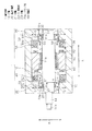
図1に示すように、工作機械が備える軸受装置1は、主軸10と、主軸10を支持する一対の転がり軸受20,30と、アキシアル方向(図中の矢印Aの方向)において転がり軸受20,30の各々と対向して配設された電磁石40,50とを備えている。
As shown in FIG. 1, a
主軸10は、図1に示すように、大径部11と、アキシアル方向Aにおいて大径部11を挟む一対の中径部12,13と、一方の中径部12からアキシアル方向Aへ突出した小径部14を有している。大径部11の外周には、積層された珪素鋼板11aが設けられるとともに、小径部14の先端には、研削用または切削用の工具14aが取り付けられている。
As shown in FIG. 1, the
転がり軸受20は、図1に示すように、主軸10の外周に設けられた内輪21と、内輪21の外周に配設された転動体としての玉22と、玉22を内輪21と挟持する外輪23とを有する。転がり軸受20は、内輪21および外輪23と玉22が接触角を有するアンギュラ軸受であるため、ラジアル方向(即ち、図中の矢印Rの方向)の荷重だけでなくアキシアル方向Aの荷重も受ける。また、転がり軸受30も、転がり軸受20と同様に、主軸10に固定された内輪31と、内輪31の外周に配置された転動体としての玉32と、玉32を内輪31と挟持する外輪33とを有するアンギュラ軸受である。アンギュラ軸受である転がり軸受20,30の各々は、内輪21,31の軌道面21a,31aと、外輪23,33の軌道面23a,33aによって、アキシアル方向Aおよびラジアル方向Rの荷重を支持する。なお、本実施形態においては、転動体は玉22,32であるが、円筒状または円錐状のころであってもよい。
As shown in FIG. 1, the rolling
また、転がり軸受20の外輪23は、図1に示すように、玉22の軌道面23aを有する本体部23bと、本体部23bに一体に設けられた円盤状のフランジ部23cにより形成されている。フランジ部23cは、図1に示すように、矢印D1の方向へ突出して、さらに外方(図中の矢印Gの方向)へ延びている。同様に、外輪33は、玉32の軌道面33aを有する本体部33bと、本体部33bに一体に設けられた円盤状のフランジ部33cにより形成されている。フランジ部33cは、図1に示すように、矢印D2の方向へ突出して、さらに外方Gへ延びている。これらフランジ部23c,33cは磁性材料により形成されている。なお、本実施形態においては、フランジ部23c,33cの各々は、外輪23,33に一体に形成されているが、一体に形成されていなくてもよく、少なくともフランジ部23c,33cが磁性材料により形成されていればよい。
Further, as shown in FIG. 1, the
電磁石40,50は、磁性体(不図示)と、磁性体に導線を巻くことによって形成されたコイル(不図示)とから構成されている。電磁石40,50の各々は、ヨーク部材41,51内に収容され、アキシアル方向Aにおいて外輪23,33の少なくとも一部(即ち、フランジ部23c,33c)と対向するように所定間隔を空けて配設されている。
The
上記構成の軸受装置1を備える工作機械は、軸受装置1の他に、主軸10をロータ(回転子)として回転させるための回転磁界を発生させるステータ(固定子)60と、転がり軸受20,30およびステータ60を保護するためのハウジング70とを備えている。即ち、ロータである主軸10とステータ60により、電動機(モータ)が構成されている。
The machine tool including the
ステータ60は、円筒状のステータコア61と、ステータコア61に巻かれた導線からなるコイル62とから構成されている。ステータコア61は軟質磁性材料により形成されているため、コイル62に電流を供給することによって回転磁界を発生させることができる。
The
ハウジング70は円筒状に形成され、その内周には、ヨーク部材41,51およびステータ60が固定されるとともに、転がり軸受20,30を保持することにより主軸10のアキシアル方向Aへの移動を規制している。
The
次に、軸受装置1を備える工作機械の動作について説明する。
ステータ60が発生させる回転磁界によって、磁性体である珪素鋼板11aにトルクが生じて、転がり軸受20,30によって支持された主軸10が回転する。そして、主軸10の回転に伴い、主軸10の先端に取り付けられた工具14aも回転する。この回転する工具14aをワーク(不図示)に押し付けることにより、工作機械はワークを研削または切削して加工することができる。
Next, operation | movement of the machine tool provided with the
Torque is generated in the
ここで、本実施形態においては、上述のごとく、軸受装置1が、外輪23の少なくとも一部と対向して配設された電磁石40を備えることに特徴がある。即ち、電磁石40に電流を供給することにより発生する磁気の吸引力によって、外輪23を図中の矢印D1の方向へ吸引する。この場合、内輪21は主軸10に固定されているため、転がり軸受20の全体が図中の矢印D1の方向へ移動することはなく、転がり軸受20に付与されている予圧が変化する。同様に、軸受装置1は、外輪33の少なくとも一部と対向して配設された電磁石50を備え、電磁石50に電流を供給することにより発生する磁気の吸引力によって、外輪33を図中の矢印D2の方向へ吸引する。その結果、転がり軸受30に付与されている予圧が変化する。各電磁石40,50に供給される電流の量に対応する転がり軸受20,30に付与されている予圧の変化は、予め知ることができるので、電磁石40,50の各々に供給される電流の制御は容易である。
Here, the present embodiment is characterized in that the
また、上述のごとく、電磁石40,50が発生させる磁気の吸引力によって、転がり軸受20,30に付与されている予圧が大きくなるように外輪23,33を吸引する。即ち、外輪23,33の軌道面23a,33aの各々を内輪21,31の軌道面21a,31aに近づける方向へ、各外輪23,33を移動させようとするため、転がり軸受20,30に付与されている予圧が大きくなる。従って、電磁石40,50は転がり軸受20,30の剛性を高めるように磁力(即ち、磁気の吸引力)を発生させる。
Further, as described above, the outer rings 23 and 33 are attracted by the magnetic attraction force generated by the
また、本実施形態においては、上述のごとく、外輪23,33は、玉22,32の軌道面23a,33aを有する本体部23b,33bと、本体部23b,33bに設けられたフランジ部23c,33cにより形成され、各電磁石40,50が、フランジ部23c,33cと対向している。
In the present embodiment, as described above, the outer rings 23 and 33 include the
上記実施形態の軸受装置1によれば、以下のような効果を得ることができる。
(1)外輪23の少なくとも一部と対向して配設された電磁石40に電流を供給することにより発生する磁力(即ち、磁気の吸引力)によって、転がり軸受20に付与されている予圧を変化させることができる。また、外輪33の少なくとも一部と対向して配設された電磁石50に電流を供給することにより発生する磁力(即ち、磁気の吸引力)によって、転がり軸受30に付与されている予圧を変化させことができる。従って、複数の転がり軸受20,30を備える場合であっても、転がり軸受20または転がり軸受30に付与されている予圧を個別に調整することができ、転がり軸受20および転がり軸受30により支持された主軸10の固有振動数を自在に調整できる。その結果、主軸10の固有振動数を、主軸10の回転数と異ならせることにより、共振が発生することを抑制することができる。
According to the
(1) The preload applied to the rolling
(2)電磁石40,50の各々は、転がり軸受20,30の剛性を高めるように磁力(即ち、磁気の吸引力)を発生させるため、転がり軸受20,30の剛性を高めることにより、転がり軸受20,30により支持された主軸10の固有振動数が大きくなる。従って、共振を抑えて主軸10をより高速に回転させることができる。
(2) Each of the
(3)電磁石40,50の各々はフランジ部23c,33cと対向しているため、フランジ部23c,33cと対向する電磁石40,50に電流を供給することにより発生する磁力を、外輪23,33に対して効果的に作用させることができ、転がり軸受20,30に付与されている予圧を効果的に調整することができる。
(3) Since each of the
また、上記実施形態において、工作機械は軸受装置1を備えているため、上記(1)乃至(3)に記載の効果と同じ効果を得ることができ、また、共振を発生することを抑えることができるため、主軸10の回転数を下げる必要がなくなり、ワークの加工能率を維持することができる。
Moreover, in the said embodiment, since the machine tool is provided with the
なお、本発明は、上記実施形態に限定されるものではなく、本発明の趣旨に基づいて種々の設計変更をすることが可能であり、それらを本発明の範囲から除外するものではない。例えば、上記実施形態は以下のように変更してもよい。 In addition, this invention is not limited to the said embodiment, A various design change is possible based on the meaning of this invention, and they are not excluded from the scope of the present invention. For example, the above embodiment may be modified as follows.
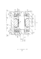
・上記実施形態においては、フランジ部23c,33cの各々は、矢印D1または矢印D2の方向へ突出して、さらに外方Gへ延びていたが、図2に示すように、外輪23,33の本体部23b,33bから外方Gへ向けて延設されていてもよい。この場合、図2に示すように、各電磁石40,50は、アキシアル方向Aにおいてフランジ部23c,33cと対向し、さらに、ラジアル方向Rにおいて本体部23b,33bと対向していることが好ましい。このようにすれば、上記(1)乃至(3)の効果を得ることができ、さらに、アキシアル方向Aにおいて電磁石40,50が配設されるスペースを小さくすることができる。
In the above-described embodiment, each of the
・上記実施形態においては、フランジ部23c,33cの各々は、外方Gへ延びていたが、図3に示すように、内方(即ち、図中の矢印Nの方向)へ延びていてもよい。このようにしても、上記(1)乃至(3)の効果を得ることができる。
In the above embodiment, each of the
・上記実施形態においては、軸受装置1は一対(2つ)の転がり軸受20,30を備えていたが、一方がその他の軸受(例えば、すべり軸受)であってもよく、また、軸受装置1が3つ以上の転がり軸受を備えていてもよい。即ち、軸受装置1が備える転がり軸受の数は適宜変更することができ、このようにしても、上記(1)の効果を得ることができる。
In the above embodiment, the
A…アキシアル方向、G…外方、R…ラジアル方向、1…軸受装置、10…主軸、20,30…転がり軸受、21,31…内輪、22,32…玉(転動体)、23,33…外輪、23a,33a…軌道面、23b,33b…本体部、23c,33c…フランジ部、40,50…電磁石、60…ステータ、70…ハウジング。 A ... Axial direction, G ... Outward, R ... Radial direction, 1 ... Bearing device, 10 ... Main shaft, 20,30 ... Rolling bearing, 21,31 ... Inner ring, 22,32 ... Ball (rolling element), 23,33 ... outer ring, 23a, 33a ... raceway surface, 23b, 33b ... main body, 23c, 33c ... flange, 40, 50 ... electromagnet, 60 ... stator, 70 ... housing.
Claims (4)
前記主軸の外周に設けられた内輪と、前記内輪の外周に配設された転動体と、前記転動体を前記内輪と挟持する外輪とを有する転がり軸受と、
前記外輪の少なくとも一部と対向して配設された電磁石とを備えることを特徴とする軸受装置。 The spindle,
A rolling bearing having an inner ring provided on the outer periphery of the main shaft, a rolling element disposed on the outer periphery of the inner ring, and an outer ring sandwiching the rolling element with the inner ring;
An electromagnet disposed opposite to at least a part of the outer ring.
前記電磁石が前記フランジ部と対向していることを特徴とする請求項1に記載の軸受装置。 The outer ring is formed by a main body portion having a raceway surface of the rolling element, and a flange portion provided in the main body portion,
The bearing device according to claim 1, wherein the electromagnet faces the flange portion.
前記電磁石は、アキシアル方向において前記フランジ部と対向し、さらに、ラジアル方向において前記本体部と対向していることを特徴とする請求項2に記載の軸受装置。 The flange portion extends outward from the main body portion,
The bearing device according to claim 2, wherein the electromagnet is opposed to the flange portion in the axial direction, and is further opposed to the main body portion in the radial direction.
Priority Applications (1)
| Application Number | Priority Date | Filing Date | Title |
|---|---|---|---|
| JP2007176254A JP2009014101A (en) | 2007-07-04 | 2007-07-04 | Bearing device and machine tool provided with the same |
Applications Claiming Priority (1)
| Application Number | Priority Date | Filing Date | Title |
|---|---|---|---|
| JP2007176254A JP2009014101A (en) | 2007-07-04 | 2007-07-04 | Bearing device and machine tool provided with the same |
Publications (1)
| Publication Number | Publication Date |
|---|---|
| JP2009014101A true JP2009014101A (en) | 2009-01-22 |
Family
ID=40355241
Family Applications (1)
| Application Number | Title | Priority Date | Filing Date |
|---|---|---|---|
| JP2007176254A Pending JP2009014101A (en) | 2007-07-04 | 2007-07-04 | Bearing device and machine tool provided with the same |
Country Status (1)
| Country | Link |
|---|---|
| JP (1) | JP2009014101A (en) |
Cited By (5)
| Publication number | Priority date | Publication date | Assignee | Title |
|---|---|---|---|---|
| JP2011079078A (en) * | 2009-10-06 | 2011-04-21 | Jtekt Corp | Spindle device of machine tool |
| KR101066740B1 (en) | 2009-03-12 | 2011-09-21 | 창원대학교 산학협력단 | Automatic preload regulating device of spindle bearing using electromagnet |
| JP2012036928A (en) * | 2010-08-04 | 2012-02-23 | Mitsubishi Electric Corp | Rotary apparatus |
| JP2020026865A (en) * | 2018-08-16 | 2020-02-20 | ミネベアミツミ株式会社 | Rotation device |
| CN114454091A (en) * | 2022-02-09 | 2022-05-10 | 广东创能精密机械有限公司 | Main shaft capable of adjusting bearing pretightening force electromagnetically |
-
2007
- 2007-07-04 JP JP2007176254A patent/JP2009014101A/en active Pending
Cited By (8)
| Publication number | Priority date | Publication date | Assignee | Title |
|---|---|---|---|---|
| KR101066740B1 (en) | 2009-03-12 | 2011-09-21 | 창원대학교 산학협력단 | Automatic preload regulating device of spindle bearing using electromagnet |
| JP2011079078A (en) * | 2009-10-06 | 2011-04-21 | Jtekt Corp | Spindle device of machine tool |
| CN102029407A (en) * | 2009-10-06 | 2011-04-27 | 株式会社捷太格特 | Spindle device for machine tool |
| US8827609B2 (en) | 2009-10-06 | 2014-09-09 | Jtekt Corporation | Spindle device for machine tool |
| CN102029407B (en) * | 2009-10-06 | 2014-10-08 | 株式会社捷太格特 | Spindle device for machine tool |
| JP2012036928A (en) * | 2010-08-04 | 2012-02-23 | Mitsubishi Electric Corp | Rotary apparatus |
| JP2020026865A (en) * | 2018-08-16 | 2020-02-20 | ミネベアミツミ株式会社 | Rotation device |
| CN114454091A (en) * | 2022-02-09 | 2022-05-10 | 广东创能精密机械有限公司 | Main shaft capable of adjusting bearing pretightening force electromagnetically |
Similar Documents
| Publication | Publication Date | Title |
|---|---|---|
| JP3602732B2 (en) | motor | |
| JP6244424B2 (en) | Method for reducing stray vector magnetic field of vacuum pump or rotary unit and vacuum pump and rotary unit | |
| JP7734230B2 (en) | Motor | |
| JP4636432B2 (en) | Rotation drive | |
| JP2008289329A (en) | Motor end plate | |
| JP2009014101A (en) | Bearing device and machine tool provided with the same | |
| JP2008254114A (en) | Magnetic bearing spindle device for machine tools | |
| JP2009002464A (en) | Magnetic bearing device and machine tool equipped with the same | |
| KR101066740B1 (en) | Automatic preload regulating device of spindle bearing using electromagnet | |
| JP2010121713A (en) | Magnetic bearing | |
| CN101722473A (en) | Device for realizing on-line active control of vibration of grinding head of non-direct drive grinding machine | |
| US10519968B2 (en) | Motor for suppressing entry of foreign matter | |
| JP7269693B2 (en) | galvano motor | |
| JP2000324755A (en) | Rotating device and processing device provided with the rotating device | |
| JP2018021572A (en) | Magnetic bearing | |
| JP2638941B2 (en) | motor | |
| JP2000283158A (en) | Radial magnetic bearing | |
| JP3267649B2 (en) | Bearing device | |
| JP2002171713A (en) | Spindle motor and manufacturing method thereof | |
| JP7683610B2 (en) | Direct Drive Motor | |
| JPH04327021A (en) | Bearing device | |
| JP4406357B2 (en) | Magnetic bearing device | |
| JP2004286175A (en) | Magnetic bearing device | |
| JP2000060056A (en) | Motor and rotary element device | |
| JP2002257135A (en) | Magnetic bearing device |