JP2009014165A - 継手 - Google Patents
継手 Download PDFInfo
- Publication number
- JP2009014165A JP2009014165A JP2007179470A JP2007179470A JP2009014165A JP 2009014165 A JP2009014165 A JP 2009014165A JP 2007179470 A JP2007179470 A JP 2007179470A JP 2007179470 A JP2007179470 A JP 2007179470A JP 2009014165 A JP2009014165 A JP 2009014165A
- Authority
- JP
- Japan
- Prior art keywords
- nose
- lock
- cover
- release member
- main body
- Prior art date
- Legal status (The legal status is an assumption and is not a legal conclusion. Google has not performed a legal analysis and makes no representation as to the accuracy of the status listed.)
- Granted
Links
- 238000003780 insertion Methods 0.000 claims abstract description 58
- 230000037431 insertion Effects 0.000 claims abstract description 58
- 239000011347 resin Substances 0.000 claims abstract description 12
- 229920005989 resin Polymers 0.000 claims abstract description 12
- 230000002093 peripheral effect Effects 0.000 claims description 40
- 235000013405 beer Nutrition 0.000 claims description 8
- 239000012530 fluid Substances 0.000 claims description 8
- 238000005299 abrasion Methods 0.000 abstract 1
- 239000007788 liquid Substances 0.000 description 6
- 230000008878 coupling Effects 0.000 description 4
- 238000010168 coupling process Methods 0.000 description 4
- 238000005859 coupling reaction Methods 0.000 description 4
- 239000002184 metal Substances 0.000 description 3
- 230000005489 elastic deformation Effects 0.000 description 2
- 238000000034 method Methods 0.000 description 2
- 235000014171 carbonated beverage Nutrition 0.000 description 1
- 230000003247 decreasing effect Effects 0.000 description 1
- 230000001105 regulatory effect Effects 0.000 description 1
Images


Landscapes
- Quick-Acting Or Multi-Walled Pipe Joints (AREA)
Abstract
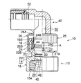
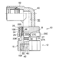
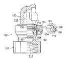
【解決手段】ボディー12には、ノーズ40が挿入される凹状挿入部14が設けられている。凹状挿入部14には、ノーズ40の外周面の周溝44に係合される凸状部22Cを備えた樹脂製のコレット22が配設されている。ボディー本体16の外周側には、カバー26が設けられており、カバー26はロック位置Aとロック解除位置Bとの間を周方向に回動する。ロック解除位置Bでは、カバー26の凹部27Cとボディー本体16の突起部30が係合し、コレット22を奥側に押し込むことで凸状部22Cと周溝44の係合が解除される。カバー26をロック位置Aからロック解除位置Bへ回動させる際には、ボディー本体16の外周面の第1の凸部32と、カバー26の内周面の第2の凸部28が当たり、カバー26の回動が規制される。
【選択図】図4
Description
12 ボディー
14 凹状挿入部
14A 挿入口
16 ボディー本体
20 流路部
22 コレット(ロック部材)
22B 端部
22C 凸状部
24 保持部材(ボディー本体)
25 溝部(凹状挿入部の奥側)
26 カバー(解除部材)
27 切り欠き部
27C 凹部
28 第2の凸部(規制部)
28A 傾斜面
28B 傾斜面
30 突起部
32 第1の凸部(規制部)
32A 傾斜面
32B 傾斜面
40 ノーズ
44 周溝
50 流路部
A ロック位置
B ロック解除位置
Claims (5)
- 一方の配管に接続されるノーズと、他方の配管に接続され、前記ノーズが挿入される凹状挿入部を有するボディーと、を備え、前記ノーズ及び前記ボディーに流体が流れる流路部が形成された継手であって、
前記凹状挿入部に設けられ、筒状体の軸方向に複数の切込みを備え、端部に前記ノーズの外周面に形成された周溝と係合する凸状部が形成された樹脂製のロック部材と、
ボディー本体の外周側にロック位置とロック解除位置との間を周方向に回動可能に設けられ、前記ロック解除位置で前記ボディー本体の軸方向の配管接続部側に移動し、前記ロック部材を前記凹状挿入部の奥側に押し込んで前記凸状部と前記周溝との係合を解除する解除部材と、
前記ボディー本体の外周面に形成された突起部と、
前記解除部材に設けられ、前記ロック解除位置で前記突起部と係合され、前記解除部材を軸方向の配管接続部側へ移動可能とする凹部と、
前記ボディー本体の外周面と前記解除部材の内周面との間に設けられ、前記解除部材を前記ロック位置から前記ロック解除位置に回動させるときに、前記解除部材の回動を規制する規制部と、
を有することを特徴とする継手。 - 前記規制部は、前記ボディー本体の外周面から径方向に突出する第1の凸部と、前記解除部材の内周面から内側に突出する第2の凸部と、を備えることを特徴とする請求項1に記載の継手。
- 前記第1の凸部及び前記第2の凸部の少なくとも一方は、前記解除部材を前記ロック位置から前記ロック解除位置に回動させるときは抵抗が大きく、前記解除部材を前記ロック解除位置から前記ロック位置に回動させるときは抵抗が小さくなるように、周方向の傾斜面の角度が調整されていることを特徴とする請求項2に記載の継手。
- 前記ボディー本体と、前記解除部材とが樹脂で形成されていることを特徴とする請求項1から請求項3までのいずれか1項に記載の継手。
- 前記流体が、ビールであることを特徴とする請求項1から請求項4までのいずれか1項に記載の継手。
Priority Applications (1)
| Application Number | Priority Date | Filing Date | Title |
|---|---|---|---|
| JP2007179470A JP5036428B2 (ja) | 2007-07-09 | 2007-07-09 | 継手 |
Applications Claiming Priority (1)
| Application Number | Priority Date | Filing Date | Title |
|---|---|---|---|
| JP2007179470A JP5036428B2 (ja) | 2007-07-09 | 2007-07-09 | 継手 |
Publications (2)
| Publication Number | Publication Date |
|---|---|
| JP2009014165A true JP2009014165A (ja) | 2009-01-22 |
| JP5036428B2 JP5036428B2 (ja) | 2012-09-26 |
Family
ID=40355294
Family Applications (1)
| Application Number | Title | Priority Date | Filing Date |
|---|---|---|---|
| JP2007179470A Expired - Fee Related JP5036428B2 (ja) | 2007-07-09 | 2007-07-09 | 継手 |
Country Status (1)
| Country | Link |
|---|---|
| JP (1) | JP5036428B2 (ja) |
Cited By (2)
| Publication number | Priority date | Publication date | Assignee | Title |
|---|---|---|---|---|
| JP2010242851A (ja) * | 2009-04-06 | 2010-10-28 | Bridgestone Corp | 継手 |
| JP2013228279A (ja) * | 2012-04-26 | 2013-11-07 | Hioki Ee Corp | フレキシブルセンサ |
-
2007
- 2007-07-09 JP JP2007179470A patent/JP5036428B2/ja not_active Expired - Fee Related
Cited By (2)
| Publication number | Priority date | Publication date | Assignee | Title |
|---|---|---|---|---|
| JP2010242851A (ja) * | 2009-04-06 | 2010-10-28 | Bridgestone Corp | 継手 |
| JP2013228279A (ja) * | 2012-04-26 | 2013-11-07 | Hioki Ee Corp | フレキシブルセンサ |
Also Published As
| Publication number | Publication date |
|---|---|
| JP5036428B2 (ja) | 2012-09-26 |
Similar Documents
| Publication | Publication Date | Title |
|---|---|---|
| US10663099B2 (en) | Pipe coupling comprising female coupling member and male coupling member | |
| JP5317760B2 (ja) | 管継手用のソケット及び管継手 | |
| US20020093194A1 (en) | Female element of a connection and quick connection incorporating such an element | |
| JP6240685B2 (ja) | 自己リセット保持機構を有するクイック結合カップリング | |
| WO2009107790A1 (ja) | 管継手用のソケット及び管継手 | |
| US12546423B2 (en) | Connecting device, in particular for producing a fluid flow circuit | |
| JP4914777B2 (ja) | 継手 | |
| JP5036428B2 (ja) | 継手 | |
| JP5779082B2 (ja) | 継手 | |
| JP4701068B2 (ja) | 管継手 | |
| JP2012159175A (ja) | 管継手 | |
| JP5253024B2 (ja) | 接続部受口構造及びそれを備えた管継手、ます、パイプ | |
| JP6171508B2 (ja) | 管継手 | |
| JP2009050530A (ja) | 医療用具の接続構造、及び、該接続構造に用いられる雄コネクタ並びに雌コネクタ | |
| JP5436157B2 (ja) | 管継手 | |
| JP5421606B2 (ja) | 管継手及び管継手の接続解除方法 | |
| JP2009144755A (ja) | 回転防止機能付き管継手 | |
| JP2008106920A (ja) | 管継手 | |
| JP2012087837A (ja) | 管継手 | |
| JP4216672B2 (ja) | ストップリング及びストップリングを備えた流体機器 | |
| JP2010270847A (ja) | 移動防止手段 | |
| JP6875109B2 (ja) | 管継手 | |
| JP4845511B2 (ja) | 管継手 | |
| JP2007292268A (ja) | 流体管の移動防止手段 | |
| JP6377493B2 (ja) | 管継手の接続構造 |
Legal Events
| Date | Code | Title | Description |
|---|---|---|---|
| A621 | Written request for application examination |
Free format text: JAPANESE INTERMEDIATE CODE: A621 Effective date: 20100607 |
|
| TRDD | Decision of grant or rejection written | ||
| A01 | Written decision to grant a patent or to grant a registration (utility model) |
Free format text: JAPANESE INTERMEDIATE CODE: A01 Effective date: 20120626 |
|
| A01 | Written decision to grant a patent or to grant a registration (utility model) |
Free format text: JAPANESE INTERMEDIATE CODE: A01 |
|
| A61 | First payment of annual fees (during grant procedure) |
Free format text: JAPANESE INTERMEDIATE CODE: A61 Effective date: 20120703 |
|
| FPAY | Renewal fee payment (event date is renewal date of database) |
Free format text: PAYMENT UNTIL: 20150713 Year of fee payment: 3 |
|
| R150 | Certificate of patent or registration of utility model |
Ref document number: 5036428 Country of ref document: JP Free format text: JAPANESE INTERMEDIATE CODE: R150 Free format text: JAPANESE INTERMEDIATE CODE: R150 |
|
| R250 | Receipt of annual fees |
Free format text: JAPANESE INTERMEDIATE CODE: R250 |
|
| R250 | Receipt of annual fees |
Free format text: JAPANESE INTERMEDIATE CODE: R250 |
|
| LAPS | Cancellation because of no payment of annual fees |