JP2009014257A - Ceiling-embedded air conditioning device - Google Patents
Ceiling-embedded air conditioning device Download PDFInfo
- Publication number
- JP2009014257A JP2009014257A JP2007175931A JP2007175931A JP2009014257A JP 2009014257 A JP2009014257 A JP 2009014257A JP 2007175931 A JP2007175931 A JP 2007175931A JP 2007175931 A JP2007175931 A JP 2007175931A JP 2009014257 A JP2009014257 A JP 2009014257A
- Authority
- JP
- Japan
- Prior art keywords
- drain
- ceiling
- main body
- air
- body case
- Prior art date
- Legal status (The legal status is an assumption and is not a legal conclusion. Google has not performed a legal analysis and makes no representation as to the accuracy of the status listed.)
- Pending
Links
Images
Landscapes
- Devices For Blowing Cold Air, Devices For Blowing Warm Air, And Means For Preventing Water Condensation In Air Conditioning Units (AREA)
Abstract
Description
本発明は、天井埋込型の空気調和装置に関する。 The present invention relates to a ceiling-embedded air conditioner.
従来、化粧パネルに形成された吸込口と吹出口とが被空調室に露出する天井埋込型空気調和装置においては、室内熱交換器から滴下するドレン水を下方で受けるドレンパンが配置され、ドレンパンに貯留されたドレン水が、ドレンポンプにより汲み上げられて外部に排出されるようになっている(例えば、特許文献1参照)。
上記従来の構成では、ドレンポンプの運転音が、空気調和装置の吸込口や吹出口等を介して、被空調室に漏れることがある。特に、圧縮機やファンが停止している場合には、ドレンポンプの運転音が際立って聞こえることがあった。 In the above-described conventional configuration, the operation sound of the drain pump may leak into the air-conditioned room through the air inlet or the outlet of the air conditioner. In particular, when the compressor and the fan are stopped, the operation sound of the drain pump may be noticeable.
そこで本発明は、天井埋込型空気調和装置において、被空調室に漏れるドレンポンプの運転音を低減することを目的とする。 Therefore, an object of the present invention is to reduce the operation sound of the drain pump leaking into the air-conditioned room in the ceiling-embedded air conditioner.
上記課題を解決するため、本発明は、化粧パネルに形成された吸込口と吹出口とが被空調室に露出する天井埋込型空気調和装置において、天井に埋め込み設置される前記本体ケースに、前記熱交換器と、この熱交換器から滴下するドレン水を受ける前記ドレンパンとを備え、前記ドレンパンのドレン水を汲み上げる前記ドレンポンプを、前記本体ケースの外側に配設したことを特徴とする天井埋込型空気調和装置を提供する。
この構成によれば、ドレンポンプが本体ケースの外側に配置されていることで、ドレンポンプの運転音が、主に天井裏で吸収され、本体ケース2内に伝わりにくく、吸込口や吹出口等を介して被空調室へ漏れにくい。これにより、例えば、ドレンポンプが本体ケースの内側に配置されている場合と比較して、被空調室に漏れるドレンポンプの運転音が大幅に低減される。
In order to solve the above-mentioned problems, the present invention provides a main body case embedded in a ceiling in a ceiling-embedded air conditioner in which an air inlet and an air outlet formed in a decorative panel are exposed to an air-conditioned room. The ceiling comprising the heat exchanger and the drain pan that receives drain water dripping from the heat exchanger, wherein the drain pump that pumps the drain water of the drain pan is disposed outside the main body case. An embedded air conditioner is provided.
According to this configuration, since the drain pump is arranged outside the main body case, the operation sound of the drain pump is mainly absorbed by the back of the ceiling and is difficult to be transmitted into the
上記構成において、前記ドレンパンが、前記熱交換器の下方に位置する前記水受け部と、この水受け部に連通して前記本体ケースの外側に突出した前記突出部とを有し、この突出部には前記水受け部に滴下したドレン水が貯留される前記貯留部が形成され、前記ドレンポンプの吸込口が、前記貯留部に貯留されたドレン水を汲み上げ可能な位置に配設された構成としても良い。
この場合、ドレンパンが、水受け部と、水受け部に連通して本体ケースの外側に突出した突出部とを有しており、この突出部に形成されたドレン水の貯留部にドレンポンプの吸込口が配置されるので、シンプルな構造で、本体ケースの外側に配置されたドレンポンプを使用してドレン水を汲み上げることができる。
In the above configuration, the drain pan includes the water receiving portion located below the heat exchanger, and the protruding portion that communicates with the water receiving portion and protrudes outside the main body case. In the configuration, the storage portion in which the drain water dripped in the water receiving portion is stored is formed, and the suction port of the drain pump is disposed at a position where the drain water stored in the storage portion can be pumped up. It is also good.
In this case, the drain pan has a water receiving portion and a protruding portion that communicates with the water receiving portion and protrudes to the outside of the main body case, and the drain water storage portion formed in the protruding portion has a drain pump. Since the suction port is arranged, the drain water can be pumped up with a simple structure using a drain pump arranged outside the main body case.
上記構成において、前記突出部と前記ドレンポンプとが、前記本体ケースの側面に取り付けられた前記サブケースに収容された構成としても良い。
この場合、本体ケースの外側にある突出部とドレンポンプとが、本体ケースの側面に取り付けられたサブケースにより完全に収容されるため、塵埃等が外部からドレンパンおよびドレンポンプに侵入することを防止できる。
The said structure WHEREIN: The said protrusion part and the said drain pump are good also as a structure accommodated in the said subcase attached to the side surface of the said main body case.
In this case, the protrusion on the outside of the main body case and the drain pump are completely accommodated by the sub case attached to the side surface of the main body case, preventing dust and the like from entering the drain pan and drain pump from the outside. it can.
上記構成において、前記突出部と前記ドレンパンとが一体に成形される構成としても良い。
この場合、突出部がドレンパンと一体に成形されることで、突出部とドレンパンとの接合部が無いため水漏れを防止でき、また、組立コストも削減される。
The said structure WHEREIN: It is good also as a structure by which the said protrusion part and the said drain pan are shape | molded integrally.
In this case, since the protruding portion is formed integrally with the drain pan, there is no joint between the protruding portion and the drain pan, so that water leakage can be prevented and the assembling cost is reduced.
本発明によれば、化粧パネルに形成された吸込口と吹出口とが被空調室に露出する天井埋込型空気調和装置において、被空調室に漏れるドレンポンプの運転音を低減できる。 ADVANTAGE OF THE INVENTION According to this invention, the operating sound of the drain pump which leaks to a to-be-air-conditioned room can be reduced in the ceiling-embedded air conditioner in which the suction inlet and the blower outlet formed in the decorative panel are exposed to the to-be-air-conditioned room.
以下、図面を参照して本発明の実施の形態を説明する。
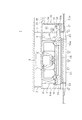
図1に、本発明の天井埋込型空気調和装置を適用した実施の形態として、空気調和装置本体1の縦断面視図を示す。図1に示すように、空気調和装置本体1は、板金製で箱型の本体ケース2に、各部が収容されて構成される。この本体ケース2は、吊りボルト3により天井から吊り下げられて天井裏に埋めこまれ、本体ケース2の下端は被空調室の天井とほぼ同じ高さにある。
Embodiments of the present invention will be described below with reference to the drawings.
FIG. 1 shows a longitudinal sectional view of an
本体ケース2には、被空調室の空気を吸い込むファン7とファン7を駆動するモータ5とが配設され、これらファン7とモータ5により送風機9が構成される。また、本体ケース2には、送風機9を取り囲むように、多角形状に曲げられた熱交換器11が配置され、熱交換器11の下方には、ファン7の吸込空気を整流するベルマウス14が取り付けられている。そして、本体ケース2の下面には、化粧パネル21が被空調室の天井板とほぼ面一に取り付けられ、この化粧パネル21には、被空調室の空気を吸い込む吸込口22と、空調された空気を被空調室に吹き出す吹出口23とが形成され、吹出口23の内側には、空気を浄化するフィルタ25が装着されている。
空気調和装置本体1は、被空調室の空気を送風機9により吸込口22から吸い込み、フィルタ25を通って浄化された被空調室の空気を、熱交換器11で温度調整した後、吹出口23から被空調室に送出する。
The
The air conditioner
熱交換器11には、図示しない室外ユニットから冷媒が供給され、この冷媒の冷熱又は熱によりファン7が吸い込んだ空気を冷却又は加温する。
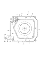
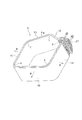
図2は、空気調和装置本体1を被空調室の側から見た平面図であり、特に熱交換器11を覆う部品を取り外した状態を示す。図3は熱交換器11の斜視図である。
図2および図3に示すように、熱交換器11は、フィン・アンド・チューブ型の熱交換器を図3中に実線矢印で示す空気の流れ方向に対して二重に重ねて構成され、五角形状に曲げて成形されている。熱交換器11の各隅部A、B、C、Dは、曲げローラ治具(図示略)にセットされた半径がRの同一のローラで曲げ成形され、隅部Eは、管板12を介して連結されている。このように、五角形状にして一部を張り出させることで、張り出させない場合と比較して熱交換器11の面積を大きくできるため、限られた空間の中で伝熱面積を増大させることができる。
Refrigerant is supplied to the
FIG. 2 is a plan view of the air conditioner
As shown in FIG. 2 and FIG. 3, the
熱交換器11を構成する5つの辺のうちの3つの辺11A、11B、11Cは、本体ケース2の3つの辺2A、2B、2Cに対し略平行であり、残りの2つの辺11D、11Eは、本体ケース2の辺2D側に向けて斜めに張り出している。そして、2つの辺11D、11Eにより形成される上記の張り出した形状に合わせて、電装箱45が取り付けられている。
また、辺11D、11Eが斜めに張り出しているため、これら辺11D、11Eの近傍では本体ケース2の内側に、比較的大きな空間が形成される。そして、辺11Eの近傍の空間には配管類27が配置されている。一方、辺11Dの近傍の空間28には特に何も配置されていない。
Of the five sides constituting the
Further, since the
熱交換器11の下方には、熱交換器11から滴下するドレン水を受けるドレンパン50が配置され、ドレン水がドレンパン50に貯留される。
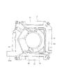
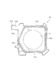
図4は図2に示す空気調和装置本体1を、被空調室の側から見た図である。この図4には、ドレンパン50、ベルマウス14および電装箱45を装着し、ドレンポンプ32等を収容しているドレンポンプキット30を取り外した状態を示す。図5はドレンポンプ32の側から見たドレンパン50の平面図である。
以下、図1から図5の各図に基づいてドレンパン50および周辺の構成について説明する。
A
FIG. 4 is a view of the air conditioner
Hereinafter, the
ドレンパン50の4辺には、空気を吹き出すための略矩形の逃げ形状が形成されており、図4に2点鎖線で示される本体ケース2との組み合わせにより、4箇所の内部吹出口41が形成される。内部吹出口41は、化粧パネル21の吹出口23に連通している。
ドレンパン50は、ベルマウス14が取り付けされる中央に略円形の吸込孔51、熱交換器11の形状に合わせて配設された略五角形の水受け部54a〜54e、および本体ケース2の側面方向の外側に突出する大きさを有した略矩形の突出部50aを備えている。
A substantially rectangular relief shape for blowing out air is formed on the four sides of the
The
本体ケース2の一つの側面には、図1に示すように、突出部50aに対応する形状の開口が設けられており、ドレンパン50が空気調和装置本体1に取り付けられた状態では、突出部50aがこの開口から本体ケース2の外側に突出している。ここで、この開口は、突出部50aを通すのに必要最小限のサイズであれば良く、例えば、突出部50aが矩形の断面であれば、これに合わせて開口も矩形に形成される。また、開口に透水性を有し吸音効果のあるスポンジ等を配置すれば、開口を介して漏れるドレンポンプ32の運転音をさらに低減できる。
突出部50aには、凹形状をしたドレン水の貯留部50bが形成されており、ドレン水がこの貯留部50bに貯留される。
As shown in FIG. 1, an opening having a shape corresponding to the
The protruding
水受け部54a〜54eには、略五角形で略環状に繋がった溝が形成されていて、この溝がドレン水の水路として機能し、この水路は貯留部50bに連通している。水受け部54a〜54eの水路の高さは、水受け部54aと水受け部54bの交点近傍が最も高く、貯留部50bに向かうに従い低くなっていて、図1に破線で示すように傾斜が付けられている。これにより、熱交換器11で発生したドレン水は、水受け部54a〜54eに滴下したあとに、水受け部54a〜54eの斜面に沿って貯留部50bに流入し貯留される。
In the
本体ケース2の外側には、ドレンポンプキット30が取り付けられている。ドレンポンプキット30は、ドレンポンプ32、ドレンポンプ32を駆動するモータ33、ドレン管34、ドレンホース接続具35、および、これらを収容する略箱型のサブケース31を備えており、サブケース31と本体ケース2とが当接した状態で、図示しないボルトにより本体ケース2に固定される。
A
サブケース31の内側に取り付けられたドレンポンプ32は、貯留部50bの上方に配置され、ドレンポンプ32の吸込口32aは、ドレンパン50に貯留されたドレン水を排水できるように、貯留部50bの中に配置される。ドレンポンプ32の吐出口には、ドレン管34の一端が接続され、ドレン管34の他端はサブケース31の上部側面に開けられた開口を通って外側に出ている。サブケース31の外側に出されたドレン管34には、ドレンホース接続具35が接続され、ドレンホース接続具35には現地で配管されるドレンホース36が接続されている。
The
ドレンポンプ32が運転されると、貯留部50bのドレン水はドレンホース36を通って外部に排水される。また、ドレンポンプキット30のサブケース31が本体ケース2に取り付けられ、突出部50aはサブケース31によって完全に収容されるため、塵埃等が突出部50aを介してドレンパン50に侵入することを防止できる。
When the
ドレンポンプキット30および突出部50aが配設される位置は、配管類27の近傍にある配管接続部の近くや、配管接続部がある本体ケース2の側面と同一面に設定されることが望ましい。この構成によれば、メンテナンス等を行う場合に、狭い天井裏で作業者が移動する必要性が減り、メンテナンス性が向上する。
また、ドレンポンプキット30と空気調和装置本体1とのパイプによる接続を、現地で据付工事者が実施する方式と比べ、本実施の形態では、この接続を吸込口32aが貯留部50bの中に配置される方式とし、工場での組立て時に完了しているため、据付工事者の手間が減り、同時に据付工事者のスキルに依存せずに確実な接続ができる。
The position where the
In addition, in this embodiment, the connection between the
貯留部50bにはドレン水が貯留されるため、埃や汚れが堆積する可能性があるが、貯留部50bが本体ケース2の外側に突出しているので、化粧パネル21やドレンパン50等を取り外すことなく、ドレンポンプキット30のサブケース31を取り外すのみで貯留部50bの清掃を行うことができる。
Since drain water is stored in the
また、ドレンポンプ32は、これまで空気調和装置本体1の内部に収容されていたものを、空気調和装置本体1の外側に移動させて使用できるので、新たなドレンポンプの設計や生産設備が必要ないため、対応が容易である。
Moreover, since the
また、ドレンポンプ32が本体ケース2の外側に配置されているため、例えば、図2に示した本体ケース2の内部の空間28にドレンポンプ32が配置された場合と比較して、熱交換器11を通過後の温度調整された空気の通風抵抗を低減できるため、被空調室への送風量のバランスが良くなる。
Further, since the
以上説明したように、本発明を適用した実施の形態によれば、ドレンポンプ32が本体ケース2の外側に配置されていることで、ドレンポンプ32の運転音が、主に天井裏で吸収され、本体ケース2内に伝わりにくい。これにより、ドレンポンプ32の運転音が、吸込口22や吹出口23等を介して被空調室へ漏れにくいため、被空調室に漏れるドレンポンプ32の運転音が低減される。
As described above, according to the embodiment to which the present invention is applied, the operation sound of the
また、ドレンパン50が、水受け部54a〜54eに連通するとともに本体ケース2の外側に突出した突出部50aを有し、吸込口32aが、貯留部50bに貯留されたドレン水を汲み上げ可能な位置に配設されているため、シンプルな構造により、本体ケース2の外側に配置されたドレンポンプ32を使用してドレン水を汲み上げることができる。
Further, the
また、本体ケース2の外側にある突出部50aとドレンポンプ32とが、本体ケース2の側面に取り付けられたサブケース31により完全に収容されるため、塵埃等が外部からドレンパン50およびドレンポンプ32に侵入することを防止できる。
Further, since the protruding
また、突出部50aとドレンパン50とが一体に成形されているため、接合部からの水漏れを防止でき、また、組立コストも削減される。
Moreover, since the
なお、上記実施の形態は本発明を適用した一態様であり、本発明は上記実施の形態に限定されるものではないのは勿論である。例えば、上記実施の形態では、略五角形の熱交換器11を備える空気調和装置本体1を例に挙げて説明したが、熱交換器11の形状は特に限定されるものではなく四角形であっても円形であっても良い。また、サブケース31には、軟質ウレタンフォーム等の吸音材を配置し、被空調室に漏れるドレンポンプ32の運転音をさらに低減する構成としても良い。
ドレンパン50は、軽量かつ製造が容易な樹脂部材に突出部50aが一体成形されたものであり、さらに断熱部材としての発砲スチロールがこの樹脂部材と一体になるように構成されているが、突出部50aを別体で製作し取り付ける構成としても良く、その他の細部構成についても任意に変更可能であることは勿論である。
In addition, the said embodiment is one aspect to which this invention is applied, and of course, this invention is not limited to the said embodiment. For example, in the above embodiment, the air conditioner
The
1 空気調和装置本体
2 本体ケース
5 モータ
7 ファン
9 送風機
11 熱交換器
14 ベルマウス
21 化粧パネル
22 吸込口
23 吹出口
30 ドレンポンプキット
31 サブケース
32 ドレンポンプ
33 モータ
34 ドレン管
35 ドレンホース接続具
36 ドレンホース
50 ドレンパン
50a 突出部
50b 貯留部
54a〜54e 水受け部
DESCRIPTION OF
Claims (4)
天井に埋め込み設置される本体ケースに、熱交換器と、この熱交換器から滴下するドレン水を受けるドレンパンと、を備え、
前記ドレンパンのドレン水を汲み上げるドレンポンプを、前記本体ケースの外側に配設したことを特徴とする天井埋込型空気調和装置。 In the ceiling-embedded air conditioner in which the air inlet and the air outlet formed in the decorative panel are exposed to the air-conditioned room,
A main body case embedded and installed in the ceiling includes a heat exchanger and a drain pan that receives drain water dripping from the heat exchanger,
A ceiling-embedded air conditioning apparatus, wherein a drain pump for pumping drain water of the drain pan is disposed outside the main body case.
前記ドレンポンプの吸込口が、前記貯留部に貯留されたドレン水を汲み上げ可能な位置に配設されたことを特徴とする天井埋込型空気調和装置。 2. The ceiling-embedded air conditioner according to claim 1, wherein the drain pan is located below the heat exchanger, and a protruding portion that communicates with the water receiving portion and protrudes outside the main body case. And a reservoir for storing drain water dripped onto the water receiver is formed in the protruding portion.
The ceiling-embedded air conditioning apparatus, wherein a suction port of the drain pump is disposed at a position where the drain water stored in the storage unit can be pumped.
Priority Applications (1)
| Application Number | Priority Date | Filing Date | Title |
|---|---|---|---|
| JP2007175931A JP2009014257A (en) | 2007-07-04 | 2007-07-04 | Ceiling-embedded air conditioning device |
Applications Claiming Priority (1)
| Application Number | Priority Date | Filing Date | Title |
|---|---|---|---|
| JP2007175931A JP2009014257A (en) | 2007-07-04 | 2007-07-04 | Ceiling-embedded air conditioning device |
Publications (1)
| Publication Number | Publication Date |
|---|---|
| JP2009014257A true JP2009014257A (en) | 2009-01-22 |
Family
ID=40355371
Family Applications (1)
| Application Number | Title | Priority Date | Filing Date |
|---|---|---|---|
| JP2007175931A Pending JP2009014257A (en) | 2007-07-04 | 2007-07-04 | Ceiling-embedded air conditioning device |
Country Status (1)
| Country | Link |
|---|---|
| JP (1) | JP2009014257A (en) |
Cited By (2)
| Publication number | Priority date | Publication date | Assignee | Title |
|---|---|---|---|---|
| KR101935256B1 (en) * | 2017-11-03 | 2019-01-04 | 삼성넥스텍(주) | Draining apparatus of air conditioner and air conditioner comprising the same |
| CN110173876A (en) * | 2019-06-25 | 2019-08-27 | 宁波奥克斯电气股份有限公司 | A kind of water receiving spiral case component and air conditioner |
-
2007
- 2007-07-04 JP JP2007175931A patent/JP2009014257A/en active Pending
Cited By (2)
| Publication number | Priority date | Publication date | Assignee | Title |
|---|---|---|---|---|
| KR101935256B1 (en) * | 2017-11-03 | 2019-01-04 | 삼성넥스텍(주) | Draining apparatus of air conditioner and air conditioner comprising the same |
| CN110173876A (en) * | 2019-06-25 | 2019-08-27 | 宁波奥克斯电气股份有限公司 | A kind of water receiving spiral case component and air conditioner |
Similar Documents
| Publication | Publication Date | Title |
|---|---|---|
| JP2014005954A (en) | Indoor equipment of air-conditioning device | |
| WO2000019150A1 (en) | Air conditioning unit | |
| JP2009204293A (en) | Air conditioner | |
| JP5123018B2 (en) | Air conditioner | |
| JP2017122526A (en) | Ceiling embedded type indoor unit | |
| JP4767179B2 (en) | Ceiling suspended air conditioner | |
| JP2009014257A (en) | Ceiling-embedded air conditioning device | |
| WO2016162977A1 (en) | Ceiling-embedded air conditioner | |
| JPH09145149A (en) | Air conditioner | |
| JP6402961B2 (en) | Air conditioner | |
| CN101655263B (en) | Indoor embedded type heat source machine | |
| JP2000046362A (en) | Ceiling cassette type air conditioner | |
| JP2003254551A (en) | Ceiling embedded type air conditioner | |
| JPH09210405A (en) | Ceiling built-in type air conditioner | |
| JP5329165B2 (en) | Embedded ceiling air conditioner | |
| JP7086615B2 (en) | Ceiling embedded air conditioner | |
| JP2013213595A (en) | Built-in air conditioner | |
| JP4388801B2 (en) | Ceiling suspended air conditioner | |
| JP3802531B2 (en) | Built-in water-cooled heat pump air conditioner | |
| JP4213725B2 (en) | Air conditioner | |
| JP5232667B2 (en) | Embedded ceiling air conditioner | |
| JP7657118B2 (en) | Air Conditioning Equipment | |
| JP7710175B2 (en) | Air conditioner indoor unit | |
| JP2010117104A (en) | Air conditioner | |
| JP2009257702A (en) | Air-conditioning device and cabinet |