JP2009014366A - Clamp type ammeter - Google Patents
Clamp type ammeter Download PDFInfo
- Publication number
- JP2009014366A JP2009014366A JP2007173656A JP2007173656A JP2009014366A JP 2009014366 A JP2009014366 A JP 2009014366A JP 2007173656 A JP2007173656 A JP 2007173656A JP 2007173656 A JP2007173656 A JP 2007173656A JP 2009014366 A JP2009014366 A JP 2009014366A
- Authority
- JP
- Japan
- Prior art keywords
- side holder
- clamp
- holder
- closed
- type ammeter
- Prior art date
- Legal status (The legal status is an assumption and is not a legal conclusion. Google has not performed a legal analysis and makes no representation as to the accuracy of the status listed.)
- Granted
Links
Images


Landscapes
- Measuring Instrument Details And Bridges, And Automatic Balancing Devices (AREA)
Abstract
【課題】捩りをかけても、突合せ端部相互が開くのを効果的に阻止できるクランプ式電流計の提供。
【解決手段】一側ホルダ部16と他側ホルダ部26とに電流センサ15,25を各別に収納し、かつ、その閉止時に当接する突合せ端部14,24を備えてなる一側センサ部13と他側センサ部23とを計器本体12に取り付けてなるクランプ式電流計11において、一側ホルダ16の開放端部16aには、先端面を開口させた凹陥部17を設け、他側ホルダ26の開放端部26aには、その閉止時に凹陥部17内に位置させる突出部27を設けるとともに、凹陥部17の内側面17aには凹部18を、該凹部18と対面する突出部27の外側面27aには凸部28を設けて閉止時に捩り方向での外力を受けた際の掛合を自在とした。
【選択図】図1Provided is a clamp-type ammeter that can effectively prevent mutual opening of butt ends even when twisted.
One side sensor unit comprising a butt end portion and abutting abutting when the current sensors are separately housed in one side holder unit and the other side holder unit, and being closed. In the clamp type ammeter 11 in which the sensor unit 23 and the other side sensor unit 23 are attached to the meter body 12, the open end portion 16 a of the one side holder 16 is provided with a recessed portion 17 having an open front end surface, and the other side holder 26. The open end 26a is provided with a protrusion 27 that is positioned in the recess 17 when closed, and the recess 18 is provided on the inner surface 17a of the recess 17 and the outer surface of the protrusion 27 facing the recess 18 is provided. 27a is provided with a convex portion 28 so as to be freely engaged when receiving an external force in the twisting direction at the time of closing.
[Selection] Figure 1
Description
本発明は、測定時の閉止した状態のもとで捩れ方向の力がかかることがあっても、突合せ端部相互を開きづらくすることで正確に測定することができるようにしたクランプ式電流計に関する技術である。 The present invention provides a clamp-type ammeter that can be accurately measured by making it difficult to open the butt ends even when a force in the torsional direction is applied in the closed state at the time of measurement. Technology.
クランプ式電流計は、活線状態にある電線等の被測定導体をクランプして測定する際に用いられ、安定した測定を行う上からは、突合せ端部相互を常に正対する位置関係のもとで当接・閉止させておく必要がある。 Clamp-type ammeters are used to clamp and measure conductors to be measured such as live wires. From the viewpoint of stable measurement, the clamped ammeter is always in a position where the butt ends are always facing each other. It is necessary to contact and close with.
下記特許文献1には、上記要請から正対する位置関係を保持させるために採用された突合せ端部構造の一例が開示されている。
上記引用文献1によれば、各突合せ端部は、その閉止時に一側ホルダ側の突起部は他側ホルダ側の凹陥部と、一側ホルダ側の凹陥部は他側ホルダ側の突起部と相互に嵌合させることで、電流センサの当接面相互を正対させて確実に当接させることができることになる。 According to the cited document 1, each butted end portion is closed when the one side holder side projection is the other side holder recess, and the one side holder side recess is the other holder side projection. By fitting them together, the contact surfaces of the current sensors can be brought into direct contact with each other and reliably contacted.
しかし、特許文献1の開示技術によれば、込み入った場所にクランプセンサ側を入れて測定する際には、測定値を表示する表示部が見づらくなってしまうので、捩って表示部を無理に見ようとすることになる。 However, according to the disclosed technique of Patent Document 1, when the measurement is performed with the clamp sensor side in a complicated place, it becomes difficult to see the display unit that displays the measurement value. I will try to see it.
このようにクランプセンサ側に捩りをかける場合には、通常状態では閉止している突合せ端部相互がこじ開けられてしまい、正確に測定することができなくなるという不都合があった。 When twisting the clamp sensor in this way, there is a problem in that the butt end portions that are closed in the normal state are pry open and accurate measurement cannot be performed.
本発明は、従来技術の上記課題に鑑みてなされたものであり、測定時に捩りをかけてしまっても、突合せ端部相互がこじ開けられてしまうのを効果的に阻止することができるクランプ式電流計を提供することに目的がある。 The present invention has been made in view of the above-described problems of the prior art, and even when twisted during measurement, a clamp-type current that can effectively prevent the butt end portions from being opened apart. The purpose is to provide a total.
本発明は、上記目的を達成すべくなされたものであり、略円環状を呈して対向配置される一側ホルダ部と他側ホルダ部とに電流センサを各別に収納し、かつ、その閉止時に相互が当接する突合せ端部を備えてなる一側センサ部と他側センサ部とを計器本体に開閉自在に取り付けてなるクランプ式電流計において、一側センサ部側の前記突合せ端部が位置する前記一側ホルダの開放端部には、先端面を開口させた凹陥部を設け、他側センサ部側の前記突合せ端部が位置する前記他側ホルダの開放端部には、その閉止時に前記凹陥部内に位置させる突出部を設けるとともに、前記凹陥部の内側面には凹部を、該凹部と対面する前記突出部の外側面には凸部を設けて閉止時に捩り方向での外力を受けた際の掛合を自在としたことを最も主要な特徴とする。 The present invention has been made to achieve the above object, and stores current sensors separately in one side holder part and the other side holder part which are arranged to face each other in a substantially annular shape, and at the time of closing the current sensor In a clamp-type ammeter in which a one-side sensor unit and a second-side sensor unit each having a butting end portion that abuts each other are attached to the meter body so as to be freely opened and closed, the butting end portion on the one-side sensor unit side is located The open end of the one side holder is provided with a recessed portion with an open front end surface, and the open end of the other side holder where the butting end on the other side sensor unit side is located Protruding portions are provided in the recessed portions, and a concave portion is provided on the inner side surface of the concave portion, and a convex portion is provided on the outer side surface of the protruding portion facing the concave portion to receive external force in the torsional direction at the time of closing. The most important feature is that the engagement is free. That.
この場合、前記凹部は、凹陥部の前記内側面における対向2面の少なくとも各一箇所に設け、前記凸部は、前記凹部と各別に対面する突出部の前記外側面に少なくとも各一箇所設けておくのが好ましい。 In this case, the concave portion is provided in at least one place on the two opposing surfaces on the inner side surface of the concave portion, and the convex portion is provided in at least one place on the outer surface of the protruding portion facing the concave portion separately. It is preferable to leave.
本発明によれば、一側ホルダの開放端部に設けた凹陥部の内側面には凹部を、他側ホルダの開放端部に設けた突出部の外側面には凸部をそれぞれ設け、閉止時に捩り方向での外力を受けた際にこれら凹部と凸部とを掛止させて、一側センサ部の突合せ端部と他側センサ部の突合せ端部とを開きづらくすることで、正確な測定を行うことができる。 According to the present invention, a concave portion is provided on the inner side surface of the recessed portion provided at the open end portion of the one side holder, and a convex portion is provided on the outer side surface of the protruding portion provided at the open end portion of the other side holder. When receiving external force in the torsional direction sometimes, the concave and convex portions are latched to make it difficult to open the butt end of the one side sensor unit and the butt end of the other side sensor unit. Measurements can be made.
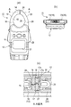
図1は、本発明の一例を示す説明図であり、そのうちの(a)は正面図を、(b)は(a)におけるA−A線矢視方向での断面図を、(c)は(b)における断面部位の拡大図をそれぞれ示す。また、図2は、左側に位置する一側ホルダの一例を示す説明図であり、そのうちの(a)は全体斜視図を、(b)は要部拡大図をそれぞれ示す。さらに、図3は、右側に位置する他側ホルダの一例を示す説明図であり、そのうちの(a)は全体斜視図を、(b)は要部拡大図をそれぞれ示す。 FIG. 1 is an explanatory diagram showing an example of the present invention, in which (a) is a front view, (b) is a cross-sectional view in the direction of arrows AA in (a), and (c) is a cross-sectional view. The enlarged view of the cross-sectional site | part in (b) is each shown. Moreover, FIG. 2 is explanatory drawing which shows an example of the one side holder located in the left side, (a) of them shows a whole perspective view, (b) shows the principal part enlarged view, respectively. Furthermore, FIG. 3 is explanatory drawing which shows an example of the other side holder located in the right side, (a) of them shows a whole perspective view, (b) shows the principal part enlarged view, respectively.
これらの図によれば、クランプ式電流計11は、略円環状を呈して対向配置される一側ホルダ部16と他側ホルダ部26とに電流センサ15,25を各別に収納し、かつ、その閉止時に相互が当接する突合せ端部14,24を備えてなる一側センサ部13と他側センサ部23とを計器本体12に開閉自在に取り付けることでその全体が形成されている。
According to these figures, the clamp-
このうち、一側センサ部13側の突合せ端部14が位置する一側ホルダ16の開放端部16aには、先端面を開口させた凹陥部17が設けられている。また、他側センサ部23側の突合せ端部24が位置する他側ホルダ26の開放端部26aには、その閉止時に凹陥部17内に位置させる突出部27が設けられている。
Among these, the
しかも、一側ホルダ16の凹陥部17の内側面17aにおける前後方向での対向2面には、凹部18が各別に設けられている。
And the
また、その閉止時に個々の凹部18と対面する他側ホルダ26の突出部27の外側面27aの開放縁側の2箇所には、凸部28が各別に設けられており、閉止時に捩り方向での外力を受けた際に対面する各凹部18との掛合が自在となっている。
In addition,
この場合における一側ホルダ16の凹部18と他側ホルダ26の凸部28とは、一側ホルダ16と他側ホルダ26とが正対して閉止される際には相互に掛合せず、閉止時に捩り方向での外力を受けた際にのみ掛合する配置関係のもとで形成されている。
In this case, the
次に、上記構成からなる本発明の作用・効果を説明すれば、クランプ式電流計11を用いた活線状態にある被測定線のクランプは、一側ホルダ部が備えるレバー19と他側ホルダ部23が備えるレバー29とを押し込んで突き合わせ端部14,24側を開いて被測定線を導入した後、レバー19,29に対する押圧力を解除することで突き合わせ端部14,24側を閉止することで行われる。
Next, the operation and effect of the present invention having the above-described configuration will be described. The clamp of the measured line in the live line state using the
この際、一側ホルダ16の凹陥部17内には、他側ホルダ26の突出部27を凸部28がその内側面17aに接触しない状態のもとで緩く送り入れることができるので、クランプ作業を円滑に行うことができることになる。
At this time, the projecting
このようにして活線状態にある被測定線をクランプした後に、クランプ式電流計11を用いた測定が行われ、表示部31を目視することで測定値を確認することができることになる。
After clamping the measurement line in the live line state in this way, measurement using the clamp-
また、込み入った場所でクランプ式電流計11を用いた測定を行う場合には、活線状態にある被測定線をクランプした後に、表示部31を目視できる位置にまで捩って表示部31に表示されている測定値を目視確認する必要が生じる。
Further, when performing measurement using the clamp-
このように活線状態にある被測定線をクランプしながら一側ホルダ16側と他側ホルダ26側とに捩り方向への力がかかると、閉止状態にある突合せ端部14,24にこじ開け方向への力がかかり、一方に偏ろうとする。
る。
In this way, when a force in the twisting direction is applied to the one
The
しかし、一側ホルダ16の凹陥部17の内側面17aには、凹部18が形成されており、他側ホルダ26の突出部27には、凸部28が形成されているので、閉止状態にある突合せ端部14,24にこじ開け方向への力がかかった際に凹部18と凸部28とが掛合することになる。
However, since the
その結果、突合せ端部14,24相互は、こじ開けられることなくその閉止状態を保つことができるので、正確で安定した測定を行うことができる。
As a result, the
以上は、本発明を図示例に基づいて説明したものであり、その具体的な内容は、本発明の要旨を逸脱しない限り、種々の変形を加えることができる。例えば、図示例では、一側ホルダ部16の凹部18が凹陥部17の内側面17aの奥端側に形成され、他側ホルダ26の凸部28が突出部27の外側面27aの開放縁側に形成されているが、相互に対応する位置関係にさえあれば、例えば凹部18をやや開口寄りの内側面17aに、凸部28を外側面27aの対応位置に形成することもできる。また、一側ホルダ部16の凹部18と他側ホルダ26の凸部28とは、対応する位置関係にさえあれば、各複数箇所に設けておくこともできる。
The above is the description of the present invention based on the illustrated examples, and various modifications can be made to the specific contents without departing from the gist of the present invention. For example, in the illustrated example, the
11 クランプ式電流計
12 計器本体
13 一側センサ部
14 突合せ端部
15 電流センサ
16 一側ホルダ部
16a 開放端部
17 凹陥部
17a 内側面
18 凹部
19 レバー
23 他側センサ部
24 突合せ端部
25 電流センサ
26 他側ホルダ部
26a 開放端部
27 突出部
27a 外側面
28 凸部
19 レバー
31 表示部
DESCRIPTION OF
Claims (2)
一側センサ部側の前記突合せ端部が位置する前記一側ホルダの開放端部には、先端面を開口させた凹陥部を設け、
他側センサ部側の前記突合せ端部が位置する前記他側ホルダの開放端部には、その閉止時に前記凹陥部内に位置させる突出部を設けるとともに、
前記凹陥部の内側面には凹部を、該凹部と対面する前記突出部の外側面には凸部を設けて閉止時に捩り方向での外力を受けた際の掛合を自在としたことを特徴とするクランプ式電流計。 A one-side sensor portion that has a substantially annular shape and stores a current sensor separately in a one-side holder portion and another-side holder portion that are arranged opposite to each other, and includes a butt end portion that contacts each other when the current sensor is closed; In the clamp-type ammeter with the other side sensor part attached to the instrument body so as to be freely opened and closed,
In the open end of the one side holder where the butt end on the one side sensor part side is located, a concave part with an open end surface is provided,
In the open end portion of the other side holder where the butting end portion on the other side sensor portion side is located, a protruding portion is provided that is positioned in the recessed portion when closed, and
A concave portion is provided on the inner side surface of the concave portion, and a convex portion is provided on the outer side surface of the projecting portion facing the concave portion, so that engagement when receiving an external force in a twisting direction at the time of closing can be freely performed. A clamp-type ammeter.
Priority Applications (1)
| Application Number | Priority Date | Filing Date | Title |
|---|---|---|---|
| JP2007173656A JP5449657B2 (en) | 2007-07-02 | 2007-07-02 | Clamp type ammeter |
Applications Claiming Priority (1)
| Application Number | Priority Date | Filing Date | Title |
|---|---|---|---|
| JP2007173656A JP5449657B2 (en) | 2007-07-02 | 2007-07-02 | Clamp type ammeter |
Publications (2)
| Publication Number | Publication Date |
|---|---|
| JP2009014366A true JP2009014366A (en) | 2009-01-22 |
| JP5449657B2 JP5449657B2 (en) | 2014-03-19 |
Family
ID=40355467
Family Applications (1)
| Application Number | Title | Priority Date | Filing Date |
|---|---|---|---|
| JP2007173656A Active JP5449657B2 (en) | 2007-07-02 | 2007-07-02 | Clamp type ammeter |
Country Status (1)
| Country | Link |
|---|---|
| JP (1) | JP5449657B2 (en) |
Cited By (3)
| Publication number | Priority date | Publication date | Assignee | Title |
|---|---|---|---|---|
| CN103487634A (en) * | 2013-10-16 | 2014-01-01 | 无锡艾科瑞思产品设计与研究有限公司 | Intelligent electricity measurer |
| US10126330B2 (en) | 2014-03-20 | 2018-11-13 | Osaka City University | Clamp-type ammeter |
| JP2019117143A (en) * | 2017-12-27 | 2019-07-18 | 日置電機株式会社 | Clamp sensor and measuring device |
Citations (1)
| Publication number | Priority date | Publication date | Assignee | Title |
|---|---|---|---|---|
| JPS63181867U (en) * | 1987-05-13 | 1988-11-24 |
-
2007
- 2007-07-02 JP JP2007173656A patent/JP5449657B2/en active Active
Patent Citations (1)
| Publication number | Priority date | Publication date | Assignee | Title |
|---|---|---|---|---|
| JPS63181867U (en) * | 1987-05-13 | 1988-11-24 |
Cited By (4)
| Publication number | Priority date | Publication date | Assignee | Title |
|---|---|---|---|---|
| CN103487634A (en) * | 2013-10-16 | 2014-01-01 | 无锡艾科瑞思产品设计与研究有限公司 | Intelligent electricity measurer |
| US10126330B2 (en) | 2014-03-20 | 2018-11-13 | Osaka City University | Clamp-type ammeter |
| JP2019117143A (en) * | 2017-12-27 | 2019-07-18 | 日置電機株式会社 | Clamp sensor and measuring device |
| JP7032130B2 (en) | 2017-12-27 | 2022-03-08 | 日置電機株式会社 | Clamp sensor and measuring device |
Also Published As
| Publication number | Publication date |
|---|---|
| JP5449657B2 (en) | 2014-03-19 |
Similar Documents
| Publication | Publication Date | Title |
|---|---|---|
| JP6010733B2 (en) | Plate-shaped specimen evaluation test unit and fixing jig used therefor | |
| US20110223799A1 (en) | Contact | |
| GB2281454A (en) | Connector inspecting apparatus | |
| JP5449657B2 (en) | Clamp type ammeter | |
| US9791479B2 (en) | Slide closure current tester | |
| JP5012326B2 (en) | Joint connector | |
| WO2017134766A1 (en) | Sealing structure and electricity meter | |
| JP6144932B2 (en) | Temperature sensor and temperature sensor assembly structure | |
| JP2014142284A (en) | Clamp type ampere meter | |
| JP5235830B2 (en) | Low voltage electrical instrument cable connector | |
| FR2959613A1 (en) | CONNECTING SYSTEM FOR SIGNALING THE TIGHTENING TORQUE OF A SCREW TERMINAL. | |
| JP2009079989A (en) | measuring device | |
| CN105058275A (en) | Clamp special for detecting thermocouple and method for detecting thermocouple | |
| KR101576668B1 (en) | Block type probe device | |
| KR20100079566A (en) | Terminal-wire harness pulling test device | |
| JP3149674U (en) | Welding groove angle measurement gauge | |
| JP5429222B2 (en) | Defect diagnosis device for electric wire coating | |
| JP5362329B2 (en) | measuring device | |
| JP6563272B2 (en) | Electrical terminal | |
| JP2839870B2 (en) | Clamp meter | |
| JP2010015707A (en) | Connector | |
| US20200067253A1 (en) | Terminal displacement amount detection method, terminal insertion method, terminal displacement amount detection device, and terminal insertion device | |
| CN111366279A (en) | Test device for the installation force of the connector wire harness pins | |
| JP6309788B2 (en) | connector | |
| JP3941367B2 (en) | Glass thickness measuring instrument |
Legal Events
| Date | Code | Title | Description |
|---|---|---|---|
| A621 | Written request for application examination |
Free format text: JAPANESE INTERMEDIATE CODE: A621 Effective date: 20100701 |
|
| A131 | Notification of reasons for refusal |
Free format text: JAPANESE INTERMEDIATE CODE: A131 Effective date: 20120822 |
|
| A521 | Request for written amendment filed |
Free format text: JAPANESE INTERMEDIATE CODE: A523 Effective date: 20121019 |
|
| A131 | Notification of reasons for refusal |
Free format text: JAPANESE INTERMEDIATE CODE: A131 Effective date: 20130911 |
|
| A521 | Request for written amendment filed |
Free format text: JAPANESE INTERMEDIATE CODE: A523 Effective date: 20131101 |
|
| TRDD | Decision of grant or rejection written | ||
| A01 | Written decision to grant a patent or to grant a registration (utility model) |
Free format text: JAPANESE INTERMEDIATE CODE: A01 Effective date: 20131211 |
|
| A61 | First payment of annual fees (during grant procedure) |
Free format text: JAPANESE INTERMEDIATE CODE: A61 Effective date: 20131225 |
|
| R150 | Certificate of patent or registration of utility model |
Free format text: JAPANESE INTERMEDIATE CODE: R150 Ref document number: 5449657 Country of ref document: JP Free format text: JAPANESE INTERMEDIATE CODE: R150 |
|
| R250 | Receipt of annual fees |
Free format text: JAPANESE INTERMEDIATE CODE: R250 |
|
| R250 | Receipt of annual fees |
Free format text: JAPANESE INTERMEDIATE CODE: R250 |
|
| R250 | Receipt of annual fees |
Free format text: JAPANESE INTERMEDIATE CODE: R250 |
|
| R250 | Receipt of annual fees |
Free format text: JAPANESE INTERMEDIATE CODE: R250 |
|
| R250 | Receipt of annual fees |
Free format text: JAPANESE INTERMEDIATE CODE: R250 |
|
| R250 | Receipt of annual fees |
Free format text: JAPANESE INTERMEDIATE CODE: R250 |