JP2009018352A - Ultrasonic cutter and driving method thereof - Google Patents
Ultrasonic cutter and driving method thereof Download PDFInfo
- Publication number
- JP2009018352A JP2009018352A JP2007180663A JP2007180663A JP2009018352A JP 2009018352 A JP2009018352 A JP 2009018352A JP 2007180663 A JP2007180663 A JP 2007180663A JP 2007180663 A JP2007180663 A JP 2007180663A JP 2009018352 A JP2009018352 A JP 2009018352A
- Authority
- JP
- Japan
- Prior art keywords
- ultrasonic cutter
- blade
- driving
- frequency
- vibration
- Prior art date
- Legal status (The legal status is an assumption and is not a legal conclusion. Google has not performed a legal analysis and makes no representation as to the accuracy of the status listed.)
- Withdrawn
Links
Images






Landscapes
- Knives (AREA)
- General Electrical Machinery Utilizing Piezoelectricity, Electrostriction Or Magnetostriction (AREA)
Abstract
Description
本発明は、超音波カッターおよびその駆動方法に関する。 The present invention relates to an ultrasonic cutter and a driving method thereof.
超音波カッターは、刃を超音波領域の周波数で振動させることによって、被切削物の切削を行う機械装置である。これまで、主に切削能力(切れ味)を高めるために、刃に加えられる振動の強度や、刃の振動に工夫がなされてきている。超音波カッターの刃の振動の仕方としては、たとえば、特開2005−153061号公報に、刃を特定の平面内で楕円状に振動させる超音波カッターが提案されている。また超音波カッターは、小型化する場合は、圧電アクチュエータ素子を駆動部として用いることが多い。このような圧電アクチュエータを用いた超音波カッターにおいては、一般に、振動の周波数が系全体の共振周波数に近いと切削能力が高くなることがわかっている。
しかしながら、刃を切削能力の高い振動状態で駆動しても、切削能力が急激に低下してしまうことがあった。本発明者は、このような現象は、刃が被切削物に侵入したときに、刃と被切削物との間の摩擦が大きくなり、当該摩擦力のほうが刃の振動する駆動力よりも大きくなると生じることを見出した。そして、刃が被切削物に侵入して、刃の振動が停止した状態では、刃が侵入する方向の静摩擦力よりも、その他の方向の静摩擦力のほうが小さいことを見出した。 However, even when the blade is driven in a vibration state having a high cutting ability, the cutting ability may be rapidly reduced. The present inventor has found that such a phenomenon is that when the blade enters the workpiece, the friction between the blade and the workpiece increases, and the friction force is larger than the driving force that the blade vibrates. I found out that it would happen. And when the blade entered the workpiece and the vibration of the blade stopped, it was found that the static friction force in the other direction is smaller than the static friction force in the direction in which the blade enters.
本発明にかかる目的の一つは、切削中に刃の振動が停止しにくく、刃の振動が停止したとしても再度刃を振動させることの可能な、超音波カッターおよびその駆動方法を提供することである。 One of the objects according to the present invention is to provide an ultrasonic cutter capable of vibrating the blade again during cutting, and capable of vibrating the blade again even if the blade vibration stops, and a driving method thereof. It is.
本発明にかかる超音波カッターの駆動方法は、
アクチュエータ部に交流電圧を入力して、該アクチュエータ部に接続された刃部を振動させる駆動工程を有し、
前記駆動工程では、振動する前記刃部の軌跡を変化させる。
The driving method of the ultrasonic cutter according to the present invention is as follows.
A drive step of inputting an alternating voltage to the actuator portion and vibrating the blade portion connected to the actuator portion;
In the driving step, the trajectory of the vibrating blade portion is changed.
このようにすれば、切削中に刃の振動が停止しにくく、刃の振動が停止したとしても再度刃を振動させることが可能である。 In this way, the vibration of the blade is difficult to stop during cutting, and even if the vibration of the blade stops, it is possible to vibrate the blade again.
本発明にかかる超音波カッターの駆動方法において、
前記交流電圧の周波数を変化させることにより、前記刃部の前記軌跡を変化させることができる。
In the driving method of the ultrasonic cutter according to the present invention,
The locus of the blade part can be changed by changing the frequency of the AC voltage.
本発明にかかる超音波カッターの駆動方法において、
前記周波数を段階的に変化させ、かつ、該周波数の変化の間隔は、100Hzないし2000Hzとすることができる。
In the driving method of the ultrasonic cutter according to the present invention,
The frequency can be changed stepwise, and the frequency change interval can be 100 Hz to 2000 Hz.
本発明にかかる超音波カッターの駆動方法において、
前記周波数を連続的に変化させることができる。
In the driving method of the ultrasonic cutter according to the present invention,
The frequency can be continuously changed.
本発明にかかる超音波カッターの駆動方法において、
前記周波数を下げることにより、前記刃部の前記軌跡を変化させることができる。
In the driving method of the ultrasonic cutter according to the present invention,
The locus of the blade can be changed by lowering the frequency.
本発明にかかる超音波カッターの駆動方法において、
前記交流電圧の位相を変化させることにより、前記刃部の前記軌跡を変化させることができる。
In the driving method of the ultrasonic cutter according to the present invention,
The locus of the blade part can be changed by changing the phase of the AC voltage.
本発明にかかる超音波カッターの駆動方法において、
前記位相を段階的に変化させ、かつ、該位相の変化の間隔は、1°ないし180°とすることができる。
In the driving method of the ultrasonic cutter according to the present invention,
The phase is changed stepwise, and the interval between the phase changes can be 1 ° to 180 °.
本発明にかかる超音波カッターの駆動方法において、
前記位相を連続的に変化させることができる。
In the driving method of the ultrasonic cutter according to the present invention,
The phase can be continuously changed.
本発明にかかる超音波カッターの駆動方法において、
前記アクチュエータ部は、平面視において、第1方向に伸縮振動し、かつ、該第1方向に垂直な第2方向に屈曲振動し、
前記刃部は、前記アクチュエータ部の端から前記第1方向に延びて設けられ、かつ、該アクチュエータ部の前記伸縮振動および前記屈曲振動の合成により、前記第1方向および前記第2方向を含む平面内で振動し、
振動する前記刃部の先端の軌跡の形状は、線分、円または楕円であることができる。
In the driving method of the ultrasonic cutter according to the present invention,
The actuator section is stretched and vibrated in a first direction and bent and vibrated in a second direction perpendicular to the first direction in a plan view,
The blade portion is provided to extend from the end of the actuator portion in the first direction, and includes a plane including the first direction and the second direction by combining the stretching vibration and the bending vibration of the actuator portion. Vibrates within,
The shape of the locus of the tip of the blade portion that vibrates may be a line segment, a circle, or an ellipse.
本発明にかかる超音波カッターの駆動方法において、
前記交流電圧の周波数の値の変化の範囲内に、当該超音波カッターの共振周波数の値を有することができる。
In the driving method of the ultrasonic cutter according to the present invention,
The value of the resonance frequency of the ultrasonic cutter can be within a range of change in the frequency value of the AC voltage.
本発明にかかる超音波カッターは、
交流電圧が入力されて振動するアクチュエータ部と、
前記アクチュエータ部に接続され、該アクチュエータ部に駆動されて振動する刃部と、を有し、
振動する前記刃部の軌跡は変化する。
The ultrasonic cutter according to the present invention is
An actuator that vibrates when AC voltage is input;
A blade portion connected to the actuator portion and driven and vibrated by the actuator portion;
The locus of the oscillating blade changes.
このような超音波カッターは、切削中に刃の振動が停止しにくく、刃の振動が停止したとしても再度刃を振動させることが可能である。 Such an ultrasonic cutter is difficult to stop the vibration of the blade during cutting, and can vibrate the blade again even if the vibration of the blade stops.
以下に本発明の好適な実施形態について、図面を参照しながら説明する。なお、以下の実施形態は、本発明の一例として説明するものである。 Preferred embodiments of the present invention will be described below with reference to the drawings. The following embodiment will be described as an example of the present invention.
1.超音波カッター400の構成
まず、本実施形態にかかる超音波カッターの構成の一例について図面を参照しながら説明する。以下には、超音波カッター400がアクチュエータ部100に刃部200が1つ設けられる場合の例を説明するが、本発明にかかる超音波カッターは、このような構成の超音波カッターのみには限定されない。本実施形態を適用できる超音波カッターとしては、以下の例示の他に、例えば、複数の刃部が配置された超音波カッターを挙げることができる。
1. Configuration of
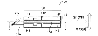
図1は、本実施形態にかかる超音波カッター400を模式的に示す平面図である。図2は、本実施形態にかかる超音波カッター400を模式的に示す断面図である。図1のA−A線に沿った断面が図2に相当する。
FIG. 1 is a plan view schematically showing an
超音波カッター400は、アクチュエータ部100と、刃部200と、を有する。
The
アクチュエータ部100は、図1および図2に例示するように、振動板110と、2つの圧電体層120,122と、2つの縦振動用電極130,132と、8つの屈曲振動用電極(一部図示せず)141,142,143,144を有する。アクチュエータ部100は、振動板110の中心面を鏡面として、上下に対称な構成であることができる。したがって、以下では、振動板110から上側の構成について説明し、振動板110より下側の構成については、詳細な説明を省略する。
As illustrated in FIG. 1 and FIG. 2, the
アクチュエータ部100は、平面視において長方形となっている。図1および図2における左右方向すなわちアクチュエータ部100の長手方向を第1方向という。そして、図1における上下方向すなわち第1方向に垂直な方向であって振動板110の面内の方向を第2方向という。図1には、第1方向および第2方向の矢印を描いた。
The
振動板110は、アクチュエータ部100の外形と一致する略長方形の板状部材である。振動板110は、刃部200に接続されている。振動板110は、上下の圧電体の伸縮によって伸縮および屈曲運動が可能で、刃部200を振動させる。この振動により、刃部200に接触した被切削物が切削される。振動板110の材質としては、たとえば、ステンレス鋼を好ましく用いることができる。振動板110は、刃部200と一体的に形成されていてもよいし、両者が機械的に結合されていても良い。
The
圧電体層120は、振動板110の上に設けられる。圧電体層120は、電圧が印加されることにより伸縮することができる。圧電体層120の伸縮の方向は、印加する電圧の極性や、圧電体層120を分極させる方向により任意に設計することができる。図1および図2の例では、4つの屈曲振動用電極141〜144を配しているため、圧電体層120は、単層で一方向に分極処理されている。この例では、各電極に印加する電圧の極性によってそれぞれの電極に対応する部位の圧電体の伸縮を行う。圧電体層120は、たとえばチタン酸ジルコン酸鉛(Pb(Zr,Ti)O3)、ニオブ酸チタン酸ジルコン酸鉛(Pb(Zr,Ti,Nb)O3)などの圧電材料から形成されることができる。
The
縦振動用電極130は、圧電体層120の上に設けられる。縦振動用電極130は、振動板110すなわちアクチュエータ部100を第1方向に伸縮するための電力を供給するために設けられる。
The
屈曲振動用電極141〜144は、圧電体層120の上に設けられる。屈曲振動用電極141〜144は、振動板110すなわちアクチュエータ部100を第2方向に屈曲振動させるための電力を供給する。屈曲振動は、屈曲振動用電極141と屈曲振動用電極142に互いに極性が反対になるような電圧を印加することによって行われる。このようにすれば一方の電極の下の圧電体が第1方向に伸張したときに、他方の電極の下の圧電体が第1方向に収縮するため、収縮する側を内側としてアクチュエータ部100が屈曲する。このような電圧の組み合わせを交番して印加すると、アクチュエータ部100は、第2方向に屈曲振動する。このような機能を有する限り、電極の数、配置および形状は任意に設計できる。また、圧電体層120の分極状態の配置を利用して屈曲および伸縮を生じさせる方法もある。
The
刃部200は、アクチュエータ部100の第1方向の一端から延びるように設けられる。図2の例では、刃部200は、振動板110と一体的に形成されている。刃部200は、振動板110と別の部材として設けられていてもよい。刃部200は、板状であり、当該板の平面は、振動板110の平面と平行になるように設けられている。刃部200は、アクチュエータ部100から第1方向に延びている。刃部200においても、当該方向を第1方向と称し、第1方向に垂直な方向は、第2方向と称する。
The
刃部200は、図示のような片刃であっても、諸刃であってもよい。刃部200は、被切削物に切り込む先鋭部210を有する。先鋭部210は、刃部200の端部に設けられ、端に行くほど薄くなって尖っている。先鋭部210は、曲線状やジグザグ状に設けることもできる。先鋭部210は、被切削物に侵入したり、被切削物から引き抜かれたり、被切削物に擦りつけられたりする。刃部200の材質は、被切削物に応じて適宜選ぶことができる。刃部200の材質は、たとえば、高硬度鋼、モリブデン鋼などとすることができる。
The
以上のような超音波カッター400は、第1方向および第2方向にそれぞれ共振周波数を有している。本実施形態の超音波カッター400は、第1方向の共振周波数と、第2方向の共振周波数とが近くなるように設計される。たとえば、超音波カッター400は、第1周波数と第2周波数の差が、−3kHzないし5kHzとなるように、全体の構造や材質が設計される。
The
2.超音波カッター400の回路構成
図3は、本実施形態の超音波カッター400の回路構成を示す模式図である。
2. Circuit Configuration of
アクチュエータ部100の各電極は、駆動回路160に電気的に接続されている。図3の例では、駆動回路160がアクチュエータ部100を駆動する構成となっている。
Each electrode of the
図3の例では、屈曲振動用電極141〜144は、移相器170を介して駆動回路160に接続されている。駆動回路160には、電力増幅回路162、発振源164等の回路を含んで構成される。移相器170は、縦振動すなわち第1方向の振動の位相と、屈曲振動すなわち第2方向の振動の位相を相対的に変化させることができる。すなわち第1方向と第2方向の振動に任意の位相差を生じさせることができる。インバータ180は、屈曲振動用電極141,144および屈曲振動用電極142,143に印加する電圧の極性を反転させる。発振源164は、駆動周波数を発生し、この駆動周波数がアクチュエータ部100に入力される交流電圧の周波数となる。発振源164は複数設けることもできる。電力増幅回路162は、発振源164で発生した信号を増幅する。このような構成の超音波カッター400を駆動するための変数は、発振源164の発振周波数(駆動周波数)、移相器170による位相差であり、これらの変数は、独立に変化させることができる。
In the example of FIG. 3, the bending
3.超音波カッター400の振動
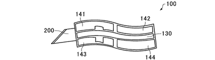
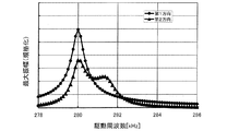
図4は、アクチュエータ部100が屈曲振動しているとき、瞬間的に採りうる形状を模式的に示す平面図である。図5は、刃部200の先端の軌跡の例を描いた模式図である。図6は、駆動周波数に対する超音波カッター400の縦方向(第1方向)の変位および屈曲方向(第2方向)の変位をそれぞれプロットした結果である。
3. Vibration of
図4に示すように、アクチュエータ部100は、各電極から印加される電圧の極性に従って、屈曲および伸縮することができる。図4は、説明のために屈曲を誇張して示している。この図の場合、屈曲振動用電極141および屈曲振動用電極144と、屈曲振動用電極142および屈曲振動用電極143に印加される電圧の極性が互いに逆になっている。すなわち、屈曲振動用電極141および屈曲振動用電極144には、圧電体層120を第1方向に伸張させる電圧が、屈曲振動用電極142および屈曲振動用電極143には、圧電体層120を第1方向に収縮させる電圧が印加されている。そのため、アクチュエータ部100は、瞬間的には図4に示すように、うねったような形状となっている。互いに極性の異なる電圧は、前述のインバータ180の作用による。そして、各電極に印加する電圧の極性を特定の周波数で交番させるため、別の瞬間にはうねりの状態が逆になるような形状となる。この交番電圧の周期でアクチュエータ部100は第2方向で屈曲振動することとなる。このとき同時に縦振動用電極130にも交流電圧が印加されるため、アクチュエータ部100には、第2方向の屈曲振動と第1方向の伸縮振動(縦振動)とを同時に発生させることができる。これら2つの振動の位相は、前述の移相器170により調節できる。これら2つの振動の組み合わせ(合成)により、刃部200の先端の軌跡は、線分、円、または楕円とすることができる。
As shown in FIG. 4, the
図6は、発振源164の周波数を横軸にとり、縦軸に刃部200の先端の第1方向および第2方向の振幅の最大値をプロットした例である。図6を見ると、第1方向の振幅の最大値は、駆動周波数が280kHz付近で最大となっている。第2方向の振幅の最大値は、駆動周波数が280kHz付近で最大となり、281.5kHz付近にショルダーを有している。このような挙動の超音波カッター400では、駆動周波数を変化させると、第1方向および第2方向の振動を合成した振動に従って、刃部200の振動が変化することになる。以下に、刃部200の先端の軌跡の変化についてさらに詳細に説明する。
FIG. 6 is an example in which the horizontal axis represents the frequency of the
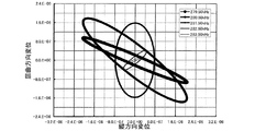
図7は、発振源164の周波数を変化させたときの刃部200の先端の軌跡を計算により求めた結果である。図8は、移相器170によって第1方向の周波数と第2方向の周波数の位相差を変化させたときの刃部200の先端の軌跡を計算により求めた結果である。
FIG. 7 shows the result of calculation of the locus of the tip of the
図7の各曲線は、駆動周波数を283.5kHzから1kHz間隔で279.5kHzまで変化させたときの、各周波数における刃部200の先端の軌跡に相当している。この計算機実験においては、駆動周波数以外の変数は変化させていない。したがって、駆動周波数を変化させることで、刃部200の楕円状の振動は、強度(楕円の大きさまたは扁平度)および方向(楕円の長軸の方向)を変化させ得ることがわかる。
Each curve in FIG. 7 corresponds to the locus of the tip of the
一方、図8の各曲線は、それぞれ第1方向の振動と第2方向の振動の位相差を、0°、90°および180°としたときの刃部200の先端の軌跡に相当している。この計算機実験においては、位相差以外の変数は変化させていない。したがって、この結果から、位相差を変化させることで、刃部200の楕円状の振動は、方向および強度を変化させ得ることがわかる。
On the other hand, each curve in FIG. 8 corresponds to the locus of the tip of the
以上の実験結果から、本実施形態の超音波カッター400は次のような特性を有することがわかる。一定の駆動周波数かつ一定の位相差で刃部200を振動させた場合は、刃部200の先端の振動の軌跡は、一定の形状となり、変化することがない。しかし、駆動周波数または位相差を変化させると、刃部200の先端の振動の軌跡は、一定ではなく方向や強度が著しく変化する。以下に説明する本実施形態の超音波カッター400の駆動方法は、以上のような特性を利用している。
From the above experimental results, it can be seen that the
4.超音波カッター400の駆動方法
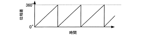
図9および図10は、本実施形態の超音波カッター400の発振源164の周波数を時間変化させるときの模式図である。図11および図12は、アクチュエータ部100の第1方向の振動および第2方向の振動のための交流電圧間の位相差を時間変化させるときの模式図である。
4). Driving Method of
本実施形態の超音波カッター400の駆動方法は、アクチュエータ部100に駆動回路160からの交流電圧を入力して、刃部200を振動させる駆動工程を有する。この駆動工程は、被切削物を切削するときに実行される。そして本実施形態の駆動方法は、被切削物を切削するときに、振動する刃部200の軌跡を変化させることに特徴を有する。本実施形態では、刃部200の軌跡を切削中に変化させるために、駆動周波数および位相差の少なくとも一方を変化させる。駆動周波数および位相差の少なくとも一方が、切削中に変化すれば、どのような態様で変化してもよい。以下に刃部200の軌跡を変化させる具体的な方法を述べる。
The driving method of the
図9および図10は、それぞれ駆動周波数の変化のさせ方の一例を示している。 9 and 10 each show an example of how to change the drive frequency.
図9は、入力する交流電圧の周波数を変化させる場合を示している。図9では、駆動周波数は、時間の経過と共に常に変化している。このように超音波カッター400の駆動周波数を変化させながら駆動すると、上述したように刃部200の先端の振動の大きさや方向が常に変化する。そのため、刃部200が被切削物に侵入する方向が常に変化することになる。したがって、刃部200と被切削物との相対的な動作の方向が常に変化するため、特定の方向の摩擦力が大きくなっても、他の方向に刃部200が運動するため、切削中に刃部200の振動が停止しにくい。さらに、切削中に被切削物に刃部200が食い込んで振動が一旦停止したとしても、次の瞬間には、刃部200は、食い込んだときの振動とは方向および強度の異なる振動をするため、再度振動を開始することができる。さらに、駆動周波数の変化が連続的な領域では、刃部200の振動の軌跡の変化が連続的になるため、この領域で切削すれば、被切削物の切断面を滑らかにすることができる。
FIG. 9 shows a case where the frequency of the input AC voltage is changed. In FIG. 9, the driving frequency is constantly changing with the passage of time. As described above, when the
また、図9に示した例は、駆動周波数をfHからfLの範囲内で連続的に変化させるものである。駆動周波数の変化の範囲内に超音波カッター400の共振周波数がくるようにfHおよびfLを選べば、共振周波数付近での切削ができるため、超音波カッター400の切削能力は、より高くなる。また、この場合、図9のように駆動周波数の変化の方向を、高い周波数(fH)から低い周波数(fL)に向かって駆動周波数を下げるようにすると、超音波カッター400の振動の始動または再始動が容易になる。
Also, the example shown in FIG. 9 is a driving frequency intended to continuously vary within the range of f H of f L. If you choose f H and f L as in the range of variation of the driving frequency comes the resonance frequency of the
一方、図10に示すように、段階的に駆動周波数を変化させることもできる。このような駆動周波数の変化の間隔(図10中fS)は、100Hzないし2000Hzとすることができる。駆動周波数を段階的に変化させると、刃部200の振動の方向などを、不連続に変化させることができるため、たとえば刃部200の振動が一旦停止したあとの再始動をより容易に行うことができる。
On the other hand, as shown in FIG. 10, the drive frequency can be changed stepwise. Such an interval (f S in FIG. 10) of the change of the driving frequency can be set to 100 Hz to 2000 Hz. When the drive frequency is changed stepwise, the direction of vibration of the
図11および図12は、それぞれ第1方向の振動と第2方向の振動の位相差を変化させる方法の一例を示している。図11に示した例は、位相差を0°から360°の範囲内で連続的に変化させるものである。このようにすれば、位相差が常に変化することになり、刃部200と被切削物との相対的な動作の方向が常に変化するため、特定の方向の摩擦力が大きくなっても、他の方向に刃部200が運動するため、切削中に刃部200の振動が停止しにくい。この例では、位相差が連続的に変化するため、被切削物の切断面を滑らかにすることができる。さらに、切削中に被切削物に刃部200が食い込んで振動が一旦停止したとしても、次の瞬間には、刃部200は、食い込んだときの振動とは方向および強度の異なる振動をするため、再度振動を開始することができる。
11 and 12 show an example of a method for changing the phase difference between the vibration in the first direction and the vibration in the second direction, respectively. In the example shown in FIG. 11, the phase difference is continuously changed within a range of 0 ° to 360 °. In this way, the phase difference always changes, and the direction of relative movement between the
位相差を変化させる場合の駆動周波数は、超音波カッター400の共振周波数付近であると超音波カッター400の切削能力が高くなる。また、図12に示すように、段階的に位相差を変化させることもできる。このような位相差の変化の間隔(図12中pS)は、1°ないし180°とすることができる。位相差を段階的に変化させると、振動の方向や強度を不連続に変化させることができるため、刃部200の振動が一旦停止したあとの再始動をより容易に行うことができる。
When the driving frequency for changing the phase difference is in the vicinity of the resonance frequency of the
ここでは駆動周波数または位相差のいずれか一方を変化させる駆動方法について述べたが、前述のように駆動周波数および位相差はそれぞれ独立に変化させることができるため、駆動工程において両者を変化させる方法もある。このようにすれば、刃部200と被切削物との相対的な動作の方向が常に複雑に変化するため、特定の方向の摩擦力が大きくなっても、他の方向に刃部200が運動するため、切削中に刃部200の振動が停止しにくい。さらに、切削中に被切削物に刃部200が食い込んで振動が一旦停止したとしても、次の瞬間には、刃部200は、食い込んだときの振動とは方向および強度の異なる振動をするため、再度振動を開始することが容易にできる。
Here, the driving method for changing either the driving frequency or the phase difference has been described. However, since the driving frequency and the phase difference can be changed independently as described above, there is a method for changing both in the driving process. is there. In this way, since the direction of relative movement between the
以上のように、本発明の実施形態について詳細に説明したが、本発明の新規事項および効果から実体的に逸脱しない多くの変形が可能であることは当業者には容易に理解できよう。従って、このような変形例はすべて本発明の範囲に含まれるものとする。 As described above, the embodiments of the present invention have been described in detail. However, it will be easily understood by those skilled in the art that many modifications can be made without departing from the novel matters and effects of the present invention. Accordingly, all such modifications are intended to be included in the scope of the present invention.
100 アクチュエータ部、110 振動板、120,122 圧電体層、
130,132 縦振動用電極、141〜144 屈曲振動用電極、
160 駆動回路、162 電力増幅回路、164 発振源、170 移相器、
180 インバータ、200 刃部、210 先鋭部、400 超音波カッター
100 Actuator part, 110 Diaphragm, 120, 122 Piezoelectric layer,
130,132 Longitudinal vibration electrode, 141-144 Bending vibration electrode,
160 drive circuit, 162 power amplifier circuit, 164 oscillation source, 170 phase shifter,
180 Inverter, 200 Blade, 210 Sharp, 400 Ultrasonic cutter
Claims (11)
前記駆動工程では、振動する前記刃部の軌跡を変化させる、超音波カッターの駆動方法。 A drive step of inputting an alternating voltage to the actuator portion and vibrating the blade portion connected to the actuator portion;
The method for driving an ultrasonic cutter, wherein in the driving step, a locus of the blade portion that vibrates is changed.
前記交流電圧の周波数を変化させることにより、前記刃部の前記軌跡を変化させる、超音波カッターの駆動方法。 In claim 1,
A method for driving an ultrasonic cutter, wherein the locus of the blade portion is changed by changing a frequency of the AC voltage.
前記周波数を段階的に変化させ、かつ、該周波数の変化の間隔は、100Hzないし2000Hzである、超音波カッターの駆動方法。 In claim 2,
The method for driving an ultrasonic cutter, wherein the frequency is changed stepwise, and the frequency change interval is 100 Hz to 2000 Hz.
前記周波数を連続的に変化させる、超音波カッターの駆動方法。 In claim 2,
An ultrasonic cutter driving method, wherein the frequency is continuously changed.
前記周波数を下げることにより、前記刃部の前記軌跡を変化させる、超音波カッターの駆動方法。 In any one of Claims 2 thru | or 4,
A method for driving an ultrasonic cutter, wherein the trajectory of the blade portion is changed by lowering the frequency.
前記交流電圧の位相を変化させることにより、前記刃部の前記軌跡を変化させる、超音波カッターの駆動方法。 In any one of Claims 1 thru | or 5,
A method for driving an ultrasonic cutter, wherein the locus of the blade portion is changed by changing a phase of the AC voltage.
前記位相を段階的に変化させ、かつ、該位相の変化の間隔は、1°ないし180°である、超音波カッターの駆動方法。 In claim 6,
The method of driving an ultrasonic cutter, wherein the phase is changed stepwise, and the interval between the phase changes is 1 ° to 180 °.
前記位相を連続的に変化させる、超音波カッターの駆動方法。 In claim 6,
An ultrasonic cutter driving method, wherein the phase is continuously changed.
前記アクチュエータ部は、平面視において、第1方向に伸縮振動し、かつ、該第1方向に垂直な第2方向に屈曲振動し、
前記刃部は、前記アクチュエータ部の端から前記第1方向に延びて設けられ、かつ、該アクチュエータ部の前記伸縮振動および前記屈曲振動の合成により、前記第1方向および前記第2方向を含む平面内で振動し、
振動する前記刃部の先端の軌跡の形状は、線分、円または楕円である、超音波カッターの駆動方法。 In any one of Claims 1 thru | or 8,
The actuator section is stretched and vibrated in a first direction and bent and vibrated in a second direction perpendicular to the first direction in a plan view,
The blade portion is provided to extend from the end of the actuator portion in the first direction, and includes a plane including the first direction and the second direction by combining the stretching vibration and the bending vibration of the actuator portion. Vibrates within,
The method of driving an ultrasonic cutter, wherein the shape of the locus of the tip of the blade portion that vibrates is a line segment, a circle, or an ellipse.
前記交流電圧の周波数の値の変化の範囲内に、当該超音波カッターの共振周波数の値を有する、超音波カッターの駆動方法。 In any one of Claims 1 thru | or 9,
A method for driving an ultrasonic cutter, wherein the value of the resonance frequency of the ultrasonic cutter is within a range of change in the frequency value of the AC voltage.
前記アクチュエータ部に接続され、該アクチュエータ部に駆動されて振動する刃部と、を有し、
振動する前記刃部の軌跡は変化する、超音波カッター。 An actuator that vibrates when AC voltage is input;
A blade portion connected to the actuator portion and driven and vibrated by the actuator portion;
An ultrasonic cutter in which the trajectory of the vibrating blade portion changes.
Priority Applications (1)
| Application Number | Priority Date | Filing Date | Title |
|---|---|---|---|
| JP2007180663A JP2009018352A (en) | 2007-07-10 | 2007-07-10 | Ultrasonic cutter and driving method thereof |
Applications Claiming Priority (1)
| Application Number | Priority Date | Filing Date | Title |
|---|---|---|---|
| JP2007180663A JP2009018352A (en) | 2007-07-10 | 2007-07-10 | Ultrasonic cutter and driving method thereof |
Publications (1)
| Publication Number | Publication Date |
|---|---|
| JP2009018352A true JP2009018352A (en) | 2009-01-29 |
Family
ID=40358444
Family Applications (1)
| Application Number | Title | Priority Date | Filing Date |
|---|---|---|---|
| JP2007180663A Withdrawn JP2009018352A (en) | 2007-07-10 | 2007-07-10 | Ultrasonic cutter and driving method thereof |
Country Status (1)
| Country | Link |
|---|---|
| JP (1) | JP2009018352A (en) |
Cited By (2)
| Publication number | Priority date | Publication date | Assignee | Title |
|---|---|---|---|---|
| JP2011030290A (en) * | 2009-07-22 | 2011-02-10 | Tdk Corp | Piezoelectric actuator and touch panel device using the same |
| JP2014532568A (en) * | 2011-11-11 | 2014-12-08 | アーテック ウルトラソニック システムズ アクチエンゲゼルシャフトArtech Ultrasonic Systems AG | Ultrasonic cutting device |
Citations (3)
| Publication number | Priority date | Publication date | Assignee | Title |
|---|---|---|---|---|
| JPS62114478A (en) * | 1985-11-11 | 1987-05-26 | Taga Denki Kk | Ultrasonic vibrator and control method for drive thereof |
| JPH03234498A (en) * | 1990-02-07 | 1991-10-18 | Taga Electric Co Ltd | Composite vibrating ultrasonic cutter |
| JP2005153061A (en) * | 2003-11-25 | 2005-06-16 | Seiko Epson Corp | Processing machine and apparatus equipped with the same |
-
2007
- 2007-07-10 JP JP2007180663A patent/JP2009018352A/en not_active Withdrawn
Patent Citations (3)
| Publication number | Priority date | Publication date | Assignee | Title |
|---|---|---|---|---|
| JPS62114478A (en) * | 1985-11-11 | 1987-05-26 | Taga Denki Kk | Ultrasonic vibrator and control method for drive thereof |
| JPH03234498A (en) * | 1990-02-07 | 1991-10-18 | Taga Electric Co Ltd | Composite vibrating ultrasonic cutter |
| JP2005153061A (en) * | 2003-11-25 | 2005-06-16 | Seiko Epson Corp | Processing machine and apparatus equipped with the same |
Cited By (3)
| Publication number | Priority date | Publication date | Assignee | Title |
|---|---|---|---|---|
| JP2011030290A (en) * | 2009-07-22 | 2011-02-10 | Tdk Corp | Piezoelectric actuator and touch panel device using the same |
| JP2014532568A (en) * | 2011-11-11 | 2014-12-08 | アーテック ウルトラソニック システムズ アクチエンゲゼルシャフトArtech Ultrasonic Systems AG | Ultrasonic cutting device |
| KR101591322B1 (en) * | 2011-11-11 | 2016-02-04 | 아르텍 울트라소닉 시스템즈 아게 | Ultrasound cutting device |
Similar Documents
| Publication | Publication Date | Title |
|---|---|---|
| JP5506552B2 (en) | Control device for vibration actuator and control method for vibration actuator | |
| JP4209465B2 (en) | Drive device | |
| JP4525943B2 (en) | Driving method of ultrasonic motor | |
| US9823543B2 (en) | Driver of vibrator, method of driving the same, lens driver, vibration device, and imaging device | |
| Yang et al. | Longitudinal and bending hybrid linear ultrasonic motor using bending PZT elements | |
| JP2010183816A (en) | Ultrasonic motor | |
| JP4814948B2 (en) | Control device for vibration actuator | |
| JP5843911B2 (en) | Device and driving method of vibration actuator | |
| JP5760748B2 (en) | Piezoelectric actuator driving method and driving unit | |
| JP2010166736A (en) | Ultrasonic motor | |
| JP4507006B2 (en) | Driving method of vibration cutter | |
| JP6497964B2 (en) | Vibrating actuator, lens barrel, camera, and control method | |
| JP2008199700A (en) | Ultrasonic motor, driving method thereof, and ultrasonic motor device | |
| JP6389662B2 (en) | Ultrasonic motor and lens driving device using ultrasonic motor | |
| JP4804154B2 (en) | Ultrasonic drive | |
| JP4593266B2 (en) | Vibrator | |
| JP2005261025A (en) | Ultrasonic motor, moving device and its driving method | |
| JP6108753B2 (en) | Ultrasonic treatment device | |
| JP2009017722A (en) | Ultrasonic motor and electronic equipment | |
| JP4129737B2 (en) | Vibration element using piezoelectric material, ultrasonic generator using the same, and ultrasonic generation method | |
| JP2011211795A (en) | Ultrasonic motor and method of driving the same | |
| JP5329912B2 (en) | Ultrasonic motor | |
| JP2005261067A (en) | Driving method of ultrasonic motor | |
| JP2013005639A5 (en) | Piezoelectric actuator, drive unit, and driving method of piezoelectric actuator | |
| CN103889354B (en) | Ultrasonic vibration apparatus |
Legal Events
| Date | Code | Title | Description |
|---|---|---|---|
| A621 | Written request for application examination |
Free format text: JAPANESE INTERMEDIATE CODE: A621 Effective date: 20100219 |
|
| A977 | Report on retrieval |
Free format text: JAPANESE INTERMEDIATE CODE: A971007 Effective date: 20120209 |
|
| A131 | Notification of reasons for refusal |
Free format text: JAPANESE INTERMEDIATE CODE: A131 Effective date: 20120229 |
|
| A761 | Written withdrawal of application |
Free format text: JAPANESE INTERMEDIATE CODE: A761 Effective date: 20120427 |