JP2009018671A - Spar-type floating structure for offshore wind power generation and manufacturing method thereof - Google Patents
Spar-type floating structure for offshore wind power generation and manufacturing method thereof Download PDFInfo
- Publication number
- JP2009018671A JP2009018671A JP2007182021A JP2007182021A JP2009018671A JP 2009018671 A JP2009018671 A JP 2009018671A JP 2007182021 A JP2007182021 A JP 2007182021A JP 2007182021 A JP2007182021 A JP 2007182021A JP 2009018671 A JP2009018671 A JP 2009018671A
- Authority
- JP
- Japan
- Prior art keywords
- floating body
- precast concrete
- concrete block
- spar
- wind power
- Prior art date
- Legal status (The legal status is an assumption and is not a legal conclusion. Google has not performed a legal analysis and makes no representation as to the accuracy of the status listed.)
- Granted
Links
Images




Classifications
-
- Y—GENERAL TAGGING OF NEW TECHNOLOGICAL DEVELOPMENTS; GENERAL TAGGING OF CROSS-SECTIONAL TECHNOLOGIES SPANNING OVER SEVERAL SECTIONS OF THE IPC; TECHNICAL SUBJECTS COVERED BY FORMER USPC CROSS-REFERENCE ART COLLECTIONS [XRACs] AND DIGESTS
- Y02—TECHNOLOGIES OR APPLICATIONS FOR MITIGATION OR ADAPTATION AGAINST CLIMATE CHANGE
- Y02E—REDUCTION OF GREENHOUSE GAS [GHG] EMISSIONS, RELATED TO ENERGY GENERATION, TRANSMISSION OR DISTRIBUTION
- Y02E10/00—Energy generation through renewable energy sources
- Y02E10/70—Wind energy
- Y02E10/727—Offshore wind turbines
Landscapes
- Wind Motors (AREA)
Abstract
Description
本願発明は洋上風力発電のスパー型浮体構造およびその製造方法に関するものである。 The present invention relates to a spar-type floating structure for offshore wind power generation and a method for manufacturing the same.
洋上風力発電の浮体構造としては、石油や天然ガスなどの海岸資源の掘削および貯蔵に用いられる浮体構造を参考にして、これまでにセミサブ型やスパー型、テンションレッグ型の浮体構造が提案されている。このうちスパー型浮体構造は全長100mを超えるものも少なくなく、その製造が陸上の製作ヤードで行われるため、スパー型浮体構造を複数製造するためには広大な製作ヤードを必要とする。またドックを利用して製造する方法も考えられるが大型のスパー型浮体構造を製造するにはコスト高になる。そのためスパー型浮体構造はほとんどが鋼構造になり、海水中における腐蝕などに対する耐久性が問題となっている。このため耐久性を高めるものとしてコンクリート製のスパー型浮体構造が考えられる。また、その他の水中構造物の剛性を高めるものとしては、例えば特開2003−252288号公報の発明が知られている。
しかし、上記のコンクリート製のスパー型浮体構造は鋼構造に比べて重量が大きく、浮力を確保するには浮体を大きくする必要があり経済的に不利であった。また浮体を大きくすると作用する波力も大きくなるため動揺も大きくなっていた。また、通常、コンクリート製のスパー型浮体構造は円筒形であるため横倒した状態で製造される。しかし、この状態でコンクリートを打設することは内外の支保工等の設備が大掛かりになることや、広大な製作ヤードが必要になることに加え、円筒断面へのコンクリートの打設には材料分離が発生し易くなるため、均質なコンクリートの打設が困難であるという問題があった。 However, the concrete spar type floating body structure is heavier than the steel structure, and it is economically disadvantageous to make the floating body large in order to ensure buoyancy. In addition, the larger the floating body, the greater the wave force that acts, and the greater the fluctuation. Moreover, since the concrete spar type floating body structure is cylindrical, it is manufactured in a laid state. However, placing concrete in this state requires large facilities such as internal and external support works, requires a large production yard, and material separation for placing concrete into a cylindrical section. Since it becomes easy to generate | occur | produce, there existed a problem that the placement of homogeneous concrete was difficult.
本願発明はこれらの問題に鑑みてなされたものであり、その目的は、軽量で耐久性に優れ、かつ短期間に製造することができる洋上風力発電のスパー型浮体構造およびその製造方法を提供することである。 The present invention has been made in view of these problems, and an object thereof is to provide a spar-type floating structure for offshore wind power generation that can be manufactured in a short period of time with a light weight and excellent durability. That is.
以上の課題を解決するための洋上風力発電のスパー型浮体構造は、上下の蓋体と、これらの間に連続的に設置された筒状のプレキャストコンクリートブロックとがPC鋼材で一体接合されてなる下部浮体と、該下部浮体にPC鋼材で一体接合された、上記プレキャストコンクリートブロックよりも小径なプレキャストコンクリートブロックと上蓋とからなる上部浮体とから構成され、下部浮体の下部内側に隔壁によって複数のバラストタンクが形成され、上部浮体の内側には隔壁によって複数の水密区画部が形成されたことを特徴とする。また下部浮体のバラストタンクの上側には内周に沿って補強用突起が設けられたことを含むものである。
また洋上風力発電のスパー型浮体構造の製造方法は、筒状のプレキャストコンクリートブロックと、筒状でかつ内側に隔壁を備えたプレキャストコンクリートブロックとを連続的に接着して筒体を形成し、該筒体の前後に蓋体を被せた後、この蓋体とプレキャストコンクリートブロックとにかけて配設したPC鋼材を所定の力で緊張して下部浮体を形成した後、該下部躯体の上面に、前記プレキャストコンクリートブロックよりも小径で内部に隔壁を備えたプレキャストコンクリートブロックを連続的に接着し、この上面に上蓋を被せた後、この蓋体とプレキャストコンクリートブロックとにかけて配設したPC鋼材を所定の力で緊張して上部浮体を形成することを特徴とする。
The spar type floating body structure of the offshore wind power generation for solving the above problems is formed by integrally joining the upper and lower lids and the cylindrical precast concrete block continuously installed between them with PC steel. A lower floating body, and an upper floating body composed of a precast concrete block having a smaller diameter than the above-mentioned precast concrete block and an upper lid, which are integrally joined to the lower floating body with a PC steel material. A tank is formed, and a plurality of watertight compartments are formed inside the upper floating body by partition walls. In addition, a reinforcing protrusion is provided on the upper side of the ballast tank of the lower floating body along the inner periphery.
In addition, a method for manufacturing a spar type floating structure for offshore wind power generation is to form a cylinder by continuously bonding a cylindrical precast concrete block and a cylindrical precast concrete block having a partition wall inside, After covering the front and back of the cylinder body, the PC steel material arranged over the cover body and the precast concrete block is tensioned with a predetermined force to form a lower floating body. A precast concrete block having a smaller diameter than the concrete block and having a partition wall inside is continuously bonded, and an upper lid is placed on the upper surface, and then the PC steel material disposed over the lid and the precast concrete block is applied with a predetermined force. It is characterized by forming an upper floating body by tension.
洋上風力発電のスパー型浮体構造を、筒状のプレキャストコンクリートブロックをPC鋼材で一体接合して構成したことにより広大な製作ヤードが不必要となった。またプレキャストコンクリートブロックをPC鋼材でプレストレスを付与して一体的に接合したことにより、部材厚が小さくなってスパー型浮体構造が軽量化される。また内側に隔壁を備えたプレキャストコンクリートブロックを連続的に接着することにより、スパー型浮体構造の下部浮体の下側に複数のバラストタンクを形成することができる。また上部浮体の内部にも隔壁によって水密区画部が形成されたことにより、船舶や漂流物が衝突した場合でもその安定性を確保することができる。 The spar-type floating structure of offshore wind power generation is constructed by integrally joining cylindrical precast concrete blocks with PC steel, making a vast production yard unnecessary. In addition, precast concrete blocks are pre-stressed with PC steel and joined together to reduce the member thickness and reduce the weight of the spar-type floating structure. Moreover, a plurality of ballast tanks can be formed on the lower side of the lower floating body of the spar type floating structure by continuously adhering a precast concrete block having a partition wall inside. Further, since the watertight compartment is formed by the partition wall in the upper floating body, the stability can be ensured even when the ship or the drifting object collides.
以下、本願発明の洋上風力発電のスパー型浮体構造(以下スパー型浮体構造という)およびその製造方法について説明する。はじめにスパー型浮体構造について説明し、次に、その製造方法について説明するが、各実施の形態において同じ構成は同じ符号を付して説明し、異なった構成にのみ異なった符号を付して説明する。 Hereinafter, the spar type floating body structure (hereinafter referred to as a spar type floating body structure) of the offshore wind power generation of the present invention and the manufacturing method thereof will be described. First, a spar type floating body structure will be described, and then a manufacturing method thereof will be described. In each embodiment, the same components will be described with the same reference numerals, and only different components will be described with different reference numerals. To do.
スパー型浮体構造1は、図1に示すように、風力発電のために洋上に直立状態に浮かべて係留チェーンBによってアンカーCに接続されて使用される。このようにスパー型浮体構造1を海上において直立させるには、後述する下部浮体3のバラストタンク4にバラスト水を注入して上部を中心に回転させる。このスパー型浮体構造1には支柱Dが接合され、該支柱DにブレードEが設置されて洋上風力発電装置Aが構成されている。
As shown in FIG. 1, the spar type floating
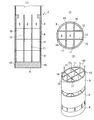
このスパー型浮体構造1は、図2〜図5に示すように、上部浮体2と下部浮体3とから構成され、該下部浮体3の下側には9つのバラストタンク4が形成されている。この下部浮体3は円筒状のプレキャストコンクリートブロック5と、円筒状でかつ内側に隔壁11、12を備えたプレキャストコンクリートブロック6とが連続的に接着されて筒体7に形成され、この筒体7の前後に蓋体8、9が被せられ、これらが蓋体8、9とプレキャストコンクリートブロック5、6とにかけて配設されたPC鋼材10によって接合されている。
As shown in FIGS. 2 to 5, the spar type
このPC鋼材10はPC鋼線やPC鋼棒などであり、円筒状のプレキャストコンクリートブロック5、6の複数箇所(8箇所)に配設され、所定の力によって緊張されて下部浮体3全体にプレストレスを付与している。また下部浮体3の下部におけるプレキャストコンクリートブロック6の内側には交差した縦横(各二枚)の隔壁11、12によって9つの区画13が形成されている。
The
したがって、このプレキャストコンクリートブロック5が複数連続して繋ぎ合わされると9つのバラストタンク4が下部浮体3の下部に形成される。またバラストタンク4の最上部におけるプレキャストコンクリートブロック6の上部には内周に沿って補強突起15が形成されている。またバラストタンク4の上部には円筒状のプレキャストコンクリートブロック5が複数接合されて中空部16を形成している。よって、この中空部16とバラストタンク4とからなる筒体7の前後が蓋体8、9で塞がれて中空の下部浮体3が形成されている。
Accordingly, when a plurality of the
このように9つものバラストタンク4を設けたのは、洋上においてスパー型浮体構造1の直立のための回転を円滑に行うとともに、直立状態での波による動揺を最小限に抑えるためである。すなわち細かく分けたバラストタンク4にバラスト水を任意の順に入れることによって、スパー型浮体構造1の円滑な傾斜と円滑な回転を行うことができ、かつ細かく分けられたバラスト水により水面変動による重心移動が小さくなって浮体の安定性を高めることができる。
The reason why nine
一方、上部浮体2は、下部浮体3のプレキャストコンクリートブロック5、6よりも小径なプレキャストコンクリートブロック17によって形成されている。このプレキャストコンクリートブロック17も円形であり、交差した縦横の隔壁19と底壁18とにより4つの区画20が形成されている。
On the other hand, the upper floating
したがって、このプレキャストコンクリートブロック17を3個連続して繋ぎ合わせ、その上部に上蓋21を被せると内側に12個の水密区画部22が形成された上部浮体2が形成される。この上蓋21とプレキャストコンクリートブロック17とは、これらと下部浮体の蓋体9とにかけて配設されたPC鋼材10によってプレストレスが付与されて接合されている。
Therefore, when three
この上部浮体2は、図1に示すように、スパー型浮体構造1を洋上に直立して浮かべたときに海面から僅かに突出する箇所に設置される。これはスパー型浮体構造1に支柱DおよびブレードEを取り付けて洋上風量発電装置Aを構成したときに、モーメントが大きく作用する箇所であるため、ここに水密区画部22を設けて補強するとともに、船舶や漂流物が衝突した場合のスパー型浮体構造1の安定性を確保するものである。
As shown in FIG. 1, the upper floating
次に、このスパー型浮体構造の製造方法を図6〜図8に基づいて説明するが、これは上部浮体2と下部浮体3とを形成した後に、これらを接合して構成するものである。まず、下部浮体3のプレキャストコンクリートブロック5、6を製造する。
Next, a method for manufacturing this spar type floating body structure will be described with reference to FIGS. 6 to 8, which are formed by forming the upper floating
これは先行して製造したプレキャストコンクリートブロックの上面を型枠代わりにしてコンクリートを打設するマッチキャスト方式で行われる。この方式はプレキャストコンクリートブロックを繋ぐ場合に接合面の誤差が生じないという利点がある。 This is performed by a match cast method in which concrete is cast using the upper surface of a precast concrete block produced in advance as a formwork. This method has the advantage that there is no error in the joint surface when connecting precast concrete blocks.
まず、図6に示すように、隔壁を備えたプレキャストコンクリートブロックを製造する場合は、先行のプレキャストコンクリートブロックの型枠24にコンクリート25を打設して先行のプレキャストコンクリートブロック26を製造する。次に、この上面に次のプレキャストコンクリートブロックの型枠27を設置し、これにコンクリート28を打設して後行のプレキャストコンクリートブロック(上部のプレキャストコンクリートブロック)29を製造する。
First, as shown in FIG. 6, when manufacturing a precast concrete block having a partition wall, a
そして、この後行のプレキャストコンクリートブロック29の上面が、その次のプレキャストコンクリートブロックの型枠として使用される。そのため、図7に示すように、後行のプレキャストコンクリートブロック(上部のプレキャストコンクリートブロック)29のコンクリート28を型枠27に打設し、このコンクリート28が硬化した後に、この後行のプレキャストコンクリートブロック29をクレーンなどで上方へ持ち上げて、先行のプレキャストコンクリートブロック26を側方へ引き出す。そして、この先行のプレキャストコンクリートブロック26を側方へ引き出した後、後行のプレキャストコンクリートブロック29を吊り降ろす。
Then, the upper surface of the subsequent
次に、この側方に引き出されたプレキャストコンクリートブロック26は型枠24を解体していないため、側方に引き出した後に型枠24を解体する(この型枠24はプレキャストコンクリートブロック26を側方に引き出す前に解体することもできる)。そして、この型枠24を解体したプレキャストコンクリートブロック26を、図8に示すように、転倒台30を用いて90度に向きを変えて門型クレーン31で移動し、スパー型浮体一基分のプレキャストコンクリートブロックが完成するまで所定の箇所に仮置きをする。
Next, since the
そして一基分のプレキャストコンクリートブロックが完成した後、すなわち中空部を形成する円筒形のプレキャストコンクリートブロック5と、バラストタンクを形成するプレキャストコンクリートブロック6とを形成した後に、各プレキャストコンクリートブロック5、6の接合面に防水パッキンを接着し、これを介してこれらのプレキャストコンクリートブロック5、6を接合して筒体7を形成し、この前後に蓋体8、9を被せる。そして、この蓋体8,9とプレキャストコンクリートブロック5、6とにかけてPC鋼材10を配設した後、これを所定の力で緊張するとプレストレスが付与された下部浮体3が完成する。
After the precast concrete block for one unit is completed, that is, after the cylindrical precast
次に、上記と同じ方法で形成した前記のプレキャストコンクリートブロック26よりも小径のプレキャストコンクリートブロック17と、上蓋21とをPC鋼材10で一体的に接合して上部浮体2を形成し、これを下部浮体3の上蓋9に接合することによって、上部浮体2と下部浮体3とからなるスパー型浮体構造1が製造される。
Next, the precast
A 洋上風力発電装置
B 係留チェーン
C アンカー
D 支柱
E ブレード
1 スパー型枠浮体構造
2 上部浮体
3 下部浮体
4 バラストタンク
5、6、17 プレキャストコンクリートブロック
7 筒体
8、9 蓋体
10 PC鋼材
11、12 隔壁
13 区画
15 補強突起
16 中空部
18 底壁
19 隔壁
20 区画
21 上蓋
22 水密区画部
24、27 型枠
25、28 コンクリート
26 先行のプレキャストコンクリートブロック
29 後行のプレキャストコンクリートブロック
30 転倒台
31 門型クレーン
A Offshore wind power generator B Mooring chain C Anchor D
Claims (3)
Priority Applications (1)
| Application Number | Priority Date | Filing Date | Title |
|---|---|---|---|
| JP2007182021A JP5022797B2 (en) | 2007-07-11 | 2007-07-11 | Spar-type floating structure for offshore wind power generation and manufacturing method thereof |
Applications Claiming Priority (1)
| Application Number | Priority Date | Filing Date | Title |
|---|---|---|---|
| JP2007182021A JP5022797B2 (en) | 2007-07-11 | 2007-07-11 | Spar-type floating structure for offshore wind power generation and manufacturing method thereof |
Publications (2)
| Publication Number | Publication Date |
|---|---|
| JP2009018671A true JP2009018671A (en) | 2009-01-29 |
| JP5022797B2 JP5022797B2 (en) | 2012-09-12 |
Family
ID=40358691
Family Applications (1)
| Application Number | Title | Priority Date | Filing Date |
|---|---|---|---|
| JP2007182021A Active JP5022797B2 (en) | 2007-07-11 | 2007-07-11 | Spar-type floating structure for offshore wind power generation and manufacturing method thereof |
Country Status (1)
| Country | Link |
|---|---|
| JP (1) | JP5022797B2 (en) |
Cited By (11)
| Publication number | Priority date | Publication date | Assignee | Title |
|---|---|---|---|---|
| JP2009248792A (en) * | 2008-04-08 | 2009-10-29 | Penta Ocean Construction Co Ltd | Spar-type floating body structure for wind power generation on ocean, manufacturing method of the same, and installation method of the same |
| WO2012121247A1 (en) | 2011-03-07 | 2012-09-13 | 株式会社アイ・エイチ・アイ マリンユナイテッド | Spar type floating structure |
| WO2013093160A1 (en) * | 2011-12-23 | 2013-06-27 | Universitat Politècnica De Catalunya | Floating precast-concrete structure for supporting a wind turbine |
| WO2014141911A1 (en) | 2013-03-13 | 2014-09-18 | 戸田建設株式会社 | Floating offshore wind power generation facility |
| WO2014163032A1 (en) * | 2013-04-01 | 2014-10-09 | 新日鐵住金株式会社 | Floating structure |
| JP2015077858A (en) * | 2013-10-16 | 2015-04-23 | 上野 康男 | Float type windmill mooring device |
| JP2015180794A (en) * | 2014-03-03 | 2015-10-15 | 尚治 池田 | tsunami evacuation structure |
| US9238896B2 (en) | 2012-12-19 | 2016-01-19 | Universitat Politècnica De Catalunya | Floating structure for supporting a wind turbine |
| JP2016520167A (en) * | 2013-04-30 | 2016-07-11 | アーセーエセ セルヴィシオス,コミュニカシオネス イ エネルジア エセ.エレ. | Submersible active support structures for turbine towers and substations or similar elements in offshore installations |
| WO2023022457A1 (en) * | 2021-08-17 | 2023-02-23 | (주)유주 | Method for constructing concrete block structure |
| JP2024508480A (en) * | 2021-02-26 | 2024-02-27 | キム,サンキ | Floating concrete block structure and its manufacturing method |
Citations (5)
| Publication number | Priority date | Publication date | Assignee | Title |
|---|---|---|---|---|
| JPS5998918A (en) * | 1982-11-29 | 1984-06-07 | Mitsui Eng & Shipbuild Co Ltd | Compartment construction work in joint of concrete marine structure |
| JP2000168676A (en) * | 1998-10-02 | 2000-06-20 | Mitsubishi Heavy Ind Ltd | Ocean rig |
| JP2002188557A (en) * | 2000-12-18 | 2002-07-05 | Mitsui Eng & Shipbuild Co Ltd | Floating wind power generator and method of installing the same |
| JP2006299631A (en) * | 2005-04-20 | 2006-11-02 | Toda Constr Co Ltd | Tower structure with variable cross section by precast method |
| JP2007071097A (en) * | 2005-09-07 | 2007-03-22 | Takenaka Komuten Co Ltd | Construction method of wind power generation tower |
-
2007
- 2007-07-11 JP JP2007182021A patent/JP5022797B2/en active Active
Patent Citations (5)
| Publication number | Priority date | Publication date | Assignee | Title |
|---|---|---|---|---|
| JPS5998918A (en) * | 1982-11-29 | 1984-06-07 | Mitsui Eng & Shipbuild Co Ltd | Compartment construction work in joint of concrete marine structure |
| JP2000168676A (en) * | 1998-10-02 | 2000-06-20 | Mitsubishi Heavy Ind Ltd | Ocean rig |
| JP2002188557A (en) * | 2000-12-18 | 2002-07-05 | Mitsui Eng & Shipbuild Co Ltd | Floating wind power generator and method of installing the same |
| JP2006299631A (en) * | 2005-04-20 | 2006-11-02 | Toda Constr Co Ltd | Tower structure with variable cross section by precast method |
| JP2007071097A (en) * | 2005-09-07 | 2007-03-22 | Takenaka Komuten Co Ltd | Construction method of wind power generation tower |
Cited By (20)
| Publication number | Priority date | Publication date | Assignee | Title |
|---|---|---|---|---|
| JP2009248792A (en) * | 2008-04-08 | 2009-10-29 | Penta Ocean Construction Co Ltd | Spar-type floating body structure for wind power generation on ocean, manufacturing method of the same, and installation method of the same |
| US9132894B2 (en) | 2011-03-07 | 2015-09-15 | Japan Marine United Corporation | Spar-type floating structure |
| WO2012121247A1 (en) | 2011-03-07 | 2012-09-13 | 株式会社アイ・エイチ・アイ マリンユナイテッド | Spar type floating structure |
| CN103517850A (en) * | 2011-03-07 | 2014-01-15 | 日本日联海洋株式会社 | Cylindrical floating structure |
| WO2013093160A1 (en) * | 2011-12-23 | 2013-06-27 | Universitat Politècnica De Catalunya | Floating precast-concrete structure for supporting a wind turbine |
| KR20140128958A (en) * | 2011-12-23 | 2014-11-06 | 유니베르시타트 폴리테크니카 데 카탈루냐 | Floating precast-concrete structure for supporting a wind turbine |
| JP2015503060A (en) * | 2011-12-23 | 2015-01-29 | ウニベルジテート ポリテクニカ デ カタル−ニア | Precast concrete structures supporting wind turbines |
| US9238896B2 (en) | 2012-12-19 | 2016-01-19 | Universitat Politècnica De Catalunya | Floating structure for supporting a wind turbine |
| WO2014141911A1 (en) | 2013-03-13 | 2014-09-18 | 戸田建設株式会社 | Floating offshore wind power generation facility |
| US9777713B2 (en) | 2013-03-13 | 2017-10-03 | Toda Corporation | Floating offshore wind power generation facility |
| WO2014163032A1 (en) * | 2013-04-01 | 2014-10-09 | 新日鐵住金株式会社 | Floating structure |
| KR20150087407A (en) * | 2013-04-01 | 2015-07-29 | 신닛테츠스미킨 카부시키카이샤 | Floating structure |
| KR101589888B1 (en) | 2013-04-01 | 2016-01-28 | 신닛테츠스미킨 카부시키카이샤 | Floating structure |
| US9533738B2 (en) | 2013-04-01 | 2017-01-03 | Nippon Steel & Sumitomo Metal Corporation | Floating body structure |
| EP3686426A1 (en) * | 2013-04-01 | 2020-07-29 | Nippon Steel Corporation | Floating body structure |
| JP2016520167A (en) * | 2013-04-30 | 2016-07-11 | アーセーエセ セルヴィシオス,コミュニカシオネス イ エネルジア エセ.エレ. | Submersible active support structures for turbine towers and substations or similar elements in offshore installations |
| JP2015077858A (en) * | 2013-10-16 | 2015-04-23 | 上野 康男 | Float type windmill mooring device |
| JP2015180794A (en) * | 2014-03-03 | 2015-10-15 | 尚治 池田 | tsunami evacuation structure |
| JP2024508480A (en) * | 2021-02-26 | 2024-02-27 | キム,サンキ | Floating concrete block structure and its manufacturing method |
| WO2023022457A1 (en) * | 2021-08-17 | 2023-02-23 | (주)유주 | Method for constructing concrete block structure |
Also Published As
| Publication number | Publication date |
|---|---|
| JP5022797B2 (en) | 2012-09-12 |
Similar Documents
| Publication | Publication Date | Title |
|---|---|---|
| JP5022797B2 (en) | Spar-type floating structure for offshore wind power generation and manufacturing method thereof | |
| JP5022976B2 (en) | Spar-type floating structure for offshore wind power generation, its manufacturing method, and its installation method | |
| KR102438810B1 (en) | How to build, assemble and launch a floating wind turbine platform | |
| CN104619984B (en) | Floating wind turbine platform and method of assembly | |
| CN107002638B (en) | Floating platform for harnessing wind energy | |
| CN104040075B (en) | A kind of method for installing offshore tower | |
| CN103228909B (en) | Method for installing offshore towers | |
| CN101032997A (en) | Water grid structure | |
| KR101647905B1 (en) | Floating-body type wind power generating device, and floating installation method for same | |
| JP2017521296A5 (en) | ||
| JP2017516945A (en) | Floating substructure for wind turbine and installation method thereof | |
| JP4453842B2 (en) | Underwater platform | |
| RU2473449C1 (en) | Navigation buoy, method of its fabrication, and spar buoy incorporated therewith | |
| KR101252709B1 (en) | Offshore floating-type structure having buoyancy preflexion, and constructing method for the same | |
| JP4844915B2 (en) | Floating structure | |
| KR20130115923A (en) | Submerged floating tunnel system | |
| JP4947456B2 (en) | Floating structure | |
| CN203942935U (en) | With the buoyancy pillar deep water mesh cage of rigidity walkway board flexible structure | |
| KR20090055225A (en) | Marine production method of floating concrete blocks | |
| KR101252708B1 (en) | Offshore floating-type structure constructing method having underwater space | |
| JP2023036533A (en) | Floating type offshore structure foundation | |
| KR20090055226A (en) | Conduction method of marine manufactured floating concrete blocks | |
| KR101315190B1 (en) | Floating Dock And Manufacturing Method For Shorestructure Using the Same | |
| JP6800493B2 (en) | Submarine installation type foundation structure | |
| CN1568676A (en) | Extra large deep water fence |
Legal Events
| Date | Code | Title | Description |
|---|---|---|---|
| A621 | Written request for application examination |
Free format text: JAPANESE INTERMEDIATE CODE: A621 Effective date: 20100310 |
|
| A977 | Report on retrieval |
Free format text: JAPANESE INTERMEDIATE CODE: A971007 Effective date: 20111117 |
|
| A131 | Notification of reasons for refusal |
Free format text: JAPANESE INTERMEDIATE CODE: A131 Effective date: 20111206 |
|
| A521 | Request for written amendment filed |
Free format text: JAPANESE INTERMEDIATE CODE: A523 Effective date: 20120125 |
|
| TRDD | Decision of grant or rejection written | ||
| A01 | Written decision to grant a patent or to grant a registration (utility model) |
Free format text: JAPANESE INTERMEDIATE CODE: A01 Effective date: 20120605 |
|
| A01 | Written decision to grant a patent or to grant a registration (utility model) |
Free format text: JAPANESE INTERMEDIATE CODE: A01 |
|
| A61 | First payment of annual fees (during grant procedure) |
Free format text: JAPANESE INTERMEDIATE CODE: A61 Effective date: 20120618 |
|
| R150 | Certificate of patent or registration of utility model |
Ref document number: 5022797 Country of ref document: JP Free format text: JAPANESE INTERMEDIATE CODE: R150 Free format text: JAPANESE INTERMEDIATE CODE: R150 |
|
| FPAY | Renewal fee payment (event date is renewal date of database) |
Free format text: PAYMENT UNTIL: 20180622 Year of fee payment: 6 |
|
| R250 | Receipt of annual fees |
Free format text: JAPANESE INTERMEDIATE CODE: R250 |
|
| R250 | Receipt of annual fees |
Free format text: JAPANESE INTERMEDIATE CODE: R250 |
|
| R250 | Receipt of annual fees |
Free format text: JAPANESE INTERMEDIATE CODE: R250 |
|
| R250 | Receipt of annual fees |
Free format text: JAPANESE INTERMEDIATE CODE: R250 |
|
| R250 | Receipt of annual fees |
Free format text: JAPANESE INTERMEDIATE CODE: R250 |
|
| R250 | Receipt of annual fees |
Free format text: JAPANESE INTERMEDIATE CODE: R250 |
|
| R250 | Receipt of annual fees |
Free format text: JAPANESE INTERMEDIATE CODE: R250 |
|
| R250 | Receipt of annual fees |
Free format text: JAPANESE INTERMEDIATE CODE: R250 |