JP2009022402A - Washing and drying machine - Google Patents
Washing and drying machine Download PDFInfo
- Publication number
- JP2009022402A JP2009022402A JP2007186620A JP2007186620A JP2009022402A JP 2009022402 A JP2009022402 A JP 2009022402A JP 2007186620 A JP2007186620 A JP 2007186620A JP 2007186620 A JP2007186620 A JP 2007186620A JP 2009022402 A JP2009022402 A JP 2009022402A
- Authority
- JP
- Japan
- Prior art keywords
- air
- drying
- tub
- outer tub
- washing
- Prior art date
- Legal status (The legal status is an assumption and is not a legal conclusion. Google has not performed a legal analysis and makes no representation as to the accuracy of the status listed.)
- Pending
Links
Images


Landscapes
- Main Body Construction Of Washing Machines And Laundry Dryers (AREA)
- Detail Structures Of Washing Machines And Dryers (AREA)
Abstract
【課題】乾燥用空気の一部が内槽内に入らずに内槽と外槽の間を通過することを抑え、衣類の乾燥効率を向上する。
【解決手段】内槽25と除湿手段38および加熱手段37とを循環するように設けた第1の循環風路36と、外槽23の内底面と前記内槽の外底面とに複数の環状突起を設けて構成したラビリンス部27と、前記外槽内の底部に送風する第2の送風手段42とを備え、前記第1の循環風路は、前記外槽内への送風口40を環状の前記ラビリンス部より回転中心側に設け、前記第2の送風手段42は、前記ラビリンス部から流出する乾燥用空気と対向するように前記ラビリンス部27の外側より送風するようにしたものである。
【選択図】図1An object of the present invention is to prevent a part of drying air from passing through an inner tub and an inner tub without entering the inner tub, thereby improving the drying efficiency of clothes.
SOLUTION: A first circulating air passage 36 provided so as to circulate an inner tank 25, a dehumidifying means 38 and a heating means 37, an inner bottom surface of the outer tank 23, and an outer bottom surface of the inner tank are provided with a plurality of rings. A labyrinth portion 27 configured by providing a protrusion and a second air blowing means 42 for blowing air to the bottom portion in the outer tub, and the first circulation air passage annularly forms an air blowing port 40 into the outer tub. The second air blowing means 42 blows air from the outside of the labyrinth portion 27 so as to face the drying air flowing out from the labyrinth portion.
[Selection] Figure 1
Description
本発明は、衣類の洗濯及び乾燥を行う洗濯乾燥機に関するものである。 The present invention relates to a washing / drying machine for washing and drying clothes.
従来のドラム式洗濯乾燥機は図5に示すような構成であった。以下、その構成について説明する。図に示すように、本体1の内部には、複数のサスペンション2によって弾性的に支持された円筒状の外槽3を設け、洗濯、脱水時の振動をサスペンション2によって吸収する構成としている。外槽3の内部には、洗濯または乾燥対象物4(以下、衣類という)を収容する円筒状で横軸型の内槽5を回転可能に配設し、駆動モータ6により回転軸を回転させて回転駆動する。内槽5の内壁には衣類を撹拌する複数のバッフル7が設けられ、内槽5の周壁には小孔5aを多数設けている。
A conventional drum type washing and drying machine has a configuration as shown in FIG. Hereinafter, the configuration will be described. As shown in the figure, a cylindrical outer tub 3 elastically supported by a plurality of
本体1の前面には衣類4を出し入れする開口部1aと、これを開閉する扉8が設けられている。外槽3および内槽5の前面側にも同様の開口部3a、5bを有し、この外槽3の開口部3aはベローズ8によって本体1の開口部1aと水密に連結されている。外槽3の下部には洗濯水を排出する排水口9を有し、排水弁10を介して排水ホース11に連結され、その先端部は本体1外に導出されている。
On the front surface of the
送風機12で送風される乾燥用空気は、冷媒を圧縮する圧縮機(図示せず)と、圧縮された冷媒の熱を放熱する放熱器13と、高圧の冷媒の圧力を減圧するための絞り手段(図示せず)と、減圧されて低圧となった冷媒が周囲から熱を奪う吸熱器14とを冷媒が循環するように管路(図示せず)で連結したヒートポンプ装置15を通過し、循環ダクト16を通り給気口17から外槽3及び内槽5内に入り、内槽5内の衣類4を通過した後排気ダクト18を通って送風機12へ戻り、循環するようになっている。
The drying air blown by the
外槽3の内底面とこれに対向する内槽5の外底面は、内槽5の回転軸を中心として複数の環状突起を設けてラビリンス部20を構成しており、送風機12で送風される乾燥用空気が内槽5の外へ漏れるのを防止している。
The inner bottom surface of the outer tub 3 and the outer bottom surface of the
上記構成において、洗濯運転を行う場合は、扉8を開いて内槽5内へ衣類4および洗剤を入れて運転を開始する。給水口より外槽3および内槽5内に所定量の水が供給されると、駆動モータ6が作動し内槽5が回転駆動され洗浄動作を行う。所定時間後、駆動モータ6が停止して排水弁10が開き、汚れた水が内槽5および外槽3から排水され、排水ホース11を介して本体1外の排水場所へ排水される。次に、上記と同様に外槽3および内槽5に水が供給され、すすぎ動作を行う。すすぎが終了すると排水弁10が開いて排水された後、内槽5が駆動モータ6により高速で回転駆動されることにより、衣類4の脱水が行われる。
In the above configuration, when the washing operation is performed, the
以上のように洗濯運転が終了すると、乾燥運転が開始する。乾燥工程では駆動モータ6により低速で内槽5を回転駆動させ衣類4を撹拌しながら、送風機12により矢印aの方向に送風された空気は、吸熱器14で除湿されたあと、放熱器13で加熱されて温風となり、吹き出し口17から外槽3及び内槽5内へ送り込まれる。この温風は、衣類4の水分を奪った後、内槽5の小孔5aから外槽3内を通過して排気口19を経て排気ダクト18へ至る。
When the washing operation is completed as described above, the drying operation is started. In the drying process, while the
この送風機12、吸熱器14、放熱器13、循環ダクト16、外槽3、内槽5、排気ダクト18の循環経路で乾燥用空気を循環させることにより、内槽5内の衣類4を乾燥させることができる(例えば、特許文献1参照)。
しかしながら、上記従来の構成では、多くの衣類を内槽5内で乾燥するときや、脱水終了後に衣類が内壁に張り付いている状態のときは、外槽3内へ送り込まれた乾燥用空気の一部は内槽5内へは入らず、排気口19から出て送風機12へ戻る経路をたどり、内槽5内の衣類と接触せず、衣類の乾燥に使われていないものがあった。
However, in the above conventional configuration, when many clothes are dried in the
本発明は、このような従来の構成の課題を解決しようとするもので、乾燥用空気の一部が内槽内に入らずに内槽と外槽の間を通過することを抑え、衣類の乾燥効率を向上して乾燥時間を短縮し、省エネ性を向上することを目的とする。 The present invention is intended to solve the problems of the conventional configuration, and prevents a part of the drying air from passing between the inner tank and the outer tank without entering the inner tank. The purpose is to improve drying efficiency, shorten drying time and improve energy saving.
上記従来の課題を解決するために、本発明の洗濯乾燥機は、内槽と除湿手段および加熱手段とを循環するように設けた第1の循環風路と、前記第1の循環風路に送風する第1の送風手段と、前記内槽を回転駆動する駆動手段と、前記駆動手段を制御する制御手段と、前記外槽の内底面と前記内槽の外底面とに複数の環状突起を設けて構成したラビリンス部と、前記外槽内の底部に送風する第2の送風手段とを備え、前記第1の循環風路は、前記外槽内への送風口を環状の前記ラビリンス部より回転中心側に設け、前記第2の送風手段は、前記ラビリンス部から流出する乾燥用空気と対向するように前記ラビリンス部の外側より送風するようにしたものである。 In order to solve the above-described conventional problems, a washing and drying machine according to the present invention includes a first circulation air passage provided to circulate an inner tub, a dehumidifying means, and a heating means, and the first circulation air passage. A plurality of annular protrusions are provided on the first air blowing means for blowing air, the driving means for rotating the inner tank, the control means for controlling the driving means, the inner bottom surface of the outer tank and the outer bottom surface of the inner tank. The labyrinth part provided and configured, and a second air blowing means for blowing air to the bottom part in the outer tub, the first circulation air passage having an air blowing port into the outer tub from the annular labyrinth part Provided on the rotation center side, the second air blowing means blows air from the outside of the labyrinth portion so as to face the drying air flowing out from the labyrinth portion.
これにより、第1の送風手段により送風した乾燥用空気の一部が内槽内に入らずに内槽と外槽の間を通過することを抑え、衣類の乾燥効率を向上して乾燥時間を短縮し、省エネ性を向上することができる。 As a result, a part of the drying air blown by the first blower means is prevented from passing between the inner tub and the outer tub without entering the inner tub, thereby improving the drying efficiency of the clothes and increasing the drying time. It can be shortened and energy saving can be improved.
本発明の洗濯乾燥機は、多くの衣類を乾燥するときや脱水終了後に衣類の内壁に衣類が張り付いている状態のときでも、第1の送風手段により送風した乾燥用空気の一部が内槽内に入らずに内槽と外槽の間を通過することを抑えることができ、衣類の乾燥効率を向上して乾燥時間を短縮し、省エネ性を向上することができる。 The washing / drying machine of the present invention has a part of the drying air blown by the first blowing means even when many clothes are dried or when the clothes are attached to the inner wall of the clothes after the dehydration. Passing between the inner tub and the outer tub without entering the tub can be suppressed, the drying efficiency of the clothes can be improved, the drying time can be shortened, and the energy saving performance can be improved.
第1の発明は、本体と、前記本体内に弾性支持した外槽と、前記外槽内に回転可能に設けた内槽と、前記内槽内に供給する乾燥用空気を除湿する除湿手段と、前記除湿手段で除湿した乾燥用空気を加熱する加熱手段と、前記内槽と除湿手段および加熱手段とを循環するように設けた第1の循環風路と、前記第1の循環風路に送風する第1の送風手段と、前記内槽を回転駆動する駆動手段と、前記駆動手段を制御する制御手段と、前記外槽の内底面と前記内槽の外底面とに複数の環状突起を設けて構成したラビリンス部と、前記外槽内の底部に送風する第2の送風手段とを備え、前記第1の循環風路は、前記外槽内への送風口を環状の前記ラビリンス部より回転中心側に設け、前記第2の送風手段は、前記ラビリンス部から流出する乾燥用空気と対向するように前記ラビリンス部の外側より送風するようにしたことにより、第1の送風手段により送風した乾燥用空気の一部が内槽内に入らずに内槽と外槽の間を通過することを抑え、衣類の乾燥効率を向上して乾燥時間を短縮し、省エネ性を向上することができる。 The first invention includes a main body, an outer tub elastically supported in the main body, an inner tub rotatably provided in the outer tub, and a dehumidifying means for dehumidifying drying air supplied into the inner tub. A heating means for heating the drying air dehumidified by the dehumidifying means, a first circulation air passage provided so as to circulate the inner tank, the dehumidification means and the heating means, and the first circulation air passage. A plurality of annular protrusions are provided on the first air blowing means for blowing air, the driving means for rotating the inner tank, the control means for controlling the driving means, the inner bottom surface of the outer tank and the outer bottom surface of the inner tank. The labyrinth part provided and configured, and a second air blowing means for blowing air to the bottom part in the outer tub, the first circulation air passage having an air blowing port into the outer tub from the annular labyrinth part Provided on the rotation center side, the second air blowing means is the drying air flowing out from the labyrinth part Since air is blown from the outside of the labyrinth so as to face each other, a part of the drying air blown by the first blower means passes between the inner tank and the outer tank without entering the inner tank. It is possible to suppress this, improve the drying efficiency of clothing, shorten the drying time, and improve energy saving.
第2の発明は、特に、第1の発明の外槽の前方と後方を接続する第2の循環風路を設け、第2の送風手段を前記第2の循環風路に設けたことにより、第1の送風手段により送風した乾燥用空気の一部が内槽内に入らずに内槽と外槽の間を通過することを抑え、衣類の乾燥効率を向上して乾燥時間を短縮し、省エネ性を向上することができる。 According to the second invention, in particular, by providing a second circulation air passage connecting the front and rear of the outer tub of the first invention, and providing a second air blowing means in the second circulation air passage, A part of the drying air blown by the first blowing means is prevented from passing between the inner tub and the outer tub without entering the inner tub, improving the drying efficiency of the clothes and reducing the drying time, Energy saving can be improved.
第3の発明は、特に、第1の発明の第2の送風手段は、一端をラビリンス部の外側に接続し、他端を開放としたことにより、第1の循環風路を流れる乾燥用空気の影響を受けることなくラビリンス部に送風することができ、第1の送風手段により送風した乾燥用空気の一部が内槽内に入らずに内槽と外槽の間を通過することを抑え、衣類の乾燥効率を向上して乾燥時間を短縮し、省エネ性を向上することができる。 In the third invention, in particular, the second air blowing means of the first invention has one end connected to the outside of the labyrinth portion and the other end opened, so that the drying air flowing through the first circulation air passage is provided. The air can be blown to the labyrinth without being affected by the air flow, and a part of the drying air blown by the first blowing means is prevented from passing between the inner tank and the outer tank without entering the inner tank. , Improve the drying efficiency of clothes, shorten the drying time, and improve energy saving.
第4の発明は、特に、第1〜第3のいずれか1つの発明の第2の送風手段は、外槽内への吹き出し部を第1の循環風路の外槽内への送風口の近傍に設けたことにより、風圧が高くなる部分でラビリンス部に送風することができ、第1の送風手段により送風した乾燥用空気の一部が内槽内に入らずに内槽と外槽の間を通過することを抑え、衣類の乾燥効率を向上して乾燥時間を短縮し、省エネ性を向上することができる。 In the fourth invention, in particular, the second air blowing means according to any one of the first to third inventions is configured such that the blowout portion into the outer tub has a blowing port into the outer tub in the first circulation air passage. By providing in the vicinity, it is possible to blow air to the labyrinth portion at the portion where the wind pressure becomes high, and a part of the drying air blown by the first blower means does not enter the inner tank and the inner tank and the outer tank. It is possible to suppress the passage between the two, improve the drying efficiency of clothing, shorten the drying time, and improve energy saving.
第5の発明は、特に、第1〜第4のいずれか1つの発明の第1の送風手段により送風された乾燥用空気がラビリンス部を通過する風量と、第2の送風手段により送風された風量が前記ラビリンス部でバランスするように設定したことにより、第2の送風手段により送風される除湿されていない乾燥用空気がラビリンス部から供給されるのを防止することができ、第1の送風手段により送風した乾燥用空気の一部が内槽内に入らずに内槽と外槽の間を通過することを抑え、衣類の乾燥効率を向上して乾燥時間を短縮し、省エネ性を向上することができる。 In the fifth invention, in particular, the drying air blown by the first blowing means of any one of the first to fourth inventions is blown by the air volume passing through the labyrinth portion and the second blowing means. By setting the air volume to be balanced by the labyrinth section, it is possible to prevent the drying air that has not been dehumidified blown by the second blowing means from being supplied from the labyrinth section, and the first blower Prevents a portion of the drying air blown by the means from passing between the inner and outer tanks without entering the inner tank, improving the drying efficiency of clothes, shortening the drying time, and improving energy saving can do.
第6の発明は、特に、第1〜第4のいずれか1つの発明の第2の送風手段の風量を第1の送風手段の風量より少なくしたことにより、さらに第1の送風手段により送風した乾燥用空気の一部が内槽内に入らずに内槽と外槽の間を通過することを抑え、衣類の乾燥効率を向上して乾燥時間を短縮し、省エネ性を向上することができる。 In the sixth aspect of the invention, in particular, since the air volume of the second air blowing means of any one of the first to fourth aspects is less than the air volume of the first air blowing means, the air is further blown by the first air blowing means. It is possible to suppress the passage of part of the drying air from entering the inner tub and the outer tub without entering the inner tub, improve the drying efficiency of clothing, shorten the drying time, and improve energy saving. .
以下、本発明の実施の形態について、図面を参照しながら説明する。なお、この実施の形態によって本発明が限定されるものではない。 Hereinafter, embodiments of the present invention will be described with reference to the drawings. Note that the present invention is not limited to the embodiments.
(実施の形態1)
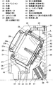
図1は、本発明の第1の実施の形態における洗濯乾燥機の断面図、図2は同洗濯乾燥機のラビンス部の拡大図である。
(Embodiment 1)
FIG. 1 is a sectional view of a washing / drying machine according to the first embodiment of the present invention, and FIG. 2 is an enlarged view of a labyrinth portion of the washing / drying machine.
本体21の内部には、複数のサスペンション22によって弾性的に支持された円筒状の外槽23を設け、洗濯、脱水時の振動をサスペンション22によって吸収する。外槽23の内部には、衣類24を収容する円筒状の内槽25を回転可能に設け、駆動手段であるモータ26により回転駆動する。外槽23の内底面と内槽25の外底面とに複数の環状突起を設けて構成したラビリンス部27を設けている。
A cylindrical
内槽25の内壁には衣類を撹拌する複数のバッフル28が設けてあり、内槽25の周壁には小孔25aを多数設けている。本体21の前面には衣類24を出し入れする開口部21aと、これを開閉する扉29が設けている。
A plurality of
外槽23および内槽25の前面側にも同様の開口部23a、25bを有し、この外槽23の開口部23aはベローズ30によって本体21の開口部21aと水密に連結している。外槽23は洗濯工程においては、衣類24の洗濯室となり、乾燥工程においては、衣類24の乾燥室となる。外槽23の下部には洗濯水を排出する排水口31を有し、排水弁32を介して排水ホース33に連結して、その先端部は本体21外に導出している。洗濯時は排水弁32を閉じて、外槽23内に所定量の洗濯水を溜めることができる。
第1の送風手段である送風ファン34は、図1に示すように本体21の上方に設けている。送風ファン34は、内槽25および外槽23を通過してきた乾燥用空気を外槽23の上方に設けた外槽排気口35から吸込み、外槽23の背面に設けた第1の循環風路36内を矢印Aの方向に送風する。
The
外槽23の背面下部には、圧縮機(図示せず)と圧縮された冷媒の熱を放熱する放熱器37と高圧の冷媒の圧力を減圧するための絞り手段(図示せず)と減圧されて低圧となった冷媒が周囲から熱を奪う吸熱器38とを冷媒が循環するように管路(図示せず)で連結したヒートポンプ装置39を配置している。ここで、ヒートポンプ装置39の吸熱器37が乾燥用空気の除湿手段となり、放熱器38が加熱手段になる。
The lower part of the rear surface of the
送風ファン34で送風した乾燥用空気は、ヒートポンプ装置39内の吸熱器38および放熱器37を通過した後、ラビリンス部27の回転中心側に設けた送風口40から外槽23内へ送風される。外槽23内へ送風した乾燥用空気の主流は内槽25内に入り、衣類24を通過した後、外槽排気口35を通って再び送風ファン34へと戻り、循環するようになっている。また、外槽23内へ送風した乾燥用空気の一部は、ラビリンス部27を通過して、内槽25外へ流れようとする。
The drying air blown by the
第2の循環風路41は外槽23の前方と後方を接続するように設けている。この第2の循環風路41内に第2の送風手段である送風ファン42を設けている。第2の送風手段である送風ファン42の吹き出し部43は、第1の循環風路36の外槽23内への送風口40近傍に設けている。第2の送風手段である送風ファン42の吹き出し部43よりラビリンス部27から流出する乾燥用空気と対向するようにラビリンス部27の外側より送風する。
The second
ヒートポンプ装置39の下部には、吸熱器38からの除湿水を貯めるドレン水容器44が設けられており、ドレン水容器44に貯まった水は排水ポンプ45から本体21外へと排出する。また、制御手段46は、駆動モータ26や排水弁32、送風ファン34、42および圧縮機等を駆動して洗濯、すすぎ、脱水、乾燥の各工程を逐次制御する。
A
以上のような構成において、次に、この動作について説明する。洗濯工程では、排水弁32を閉じた状態で外槽23内に所定の水位に達するまで給水を行い、駆動モータ26により衣類24と洗浄水の入った内槽25を回転させて衣類24の洗濯を行う。また、洗濯後のすすぎ工程でも、洗濯工程と同様に外槽23内に給水を行い、内槽25を回転させて衣類24の濯ぎを行う。
Next, the operation of the above configuration will be described. In the washing process, water is supplied until the water level reaches a predetermined water level in the
脱水工程では、排水弁32を開いて本体21外へ水を排水した後、駆動モータ26により衣類24の入った内槽25を高速回転して脱水する。脱水後の衣類24は内槽25の回転による遠心力により内槽25の内壁に張り付いた状態になっている。
In the dehydration step, the
乾燥工程では、ヒートポンプ装置39の圧縮機(図示せず)を作動させると、冷媒が圧縮され、この圧力により放熱器37、絞り手段(図示せず)、吸熱器38を循環する。放熱器38では冷媒の圧縮の熱が放出され、吸熱器37では絞り手段で減圧されて低圧となった冷媒により熱が吸収される。
In the drying process, when the compressor (not shown) of the
このとき、第1の送風手段である送風ファン34が作動し、放熱器37の放熱により加熱された乾燥用空気が第1の循環風路36を通って送風口40から外槽23内へ送風される。外槽23内へ送風した乾燥用空気の主流は内槽25内に入り、衣類24と接触して衣類24から水分を奪い衣類24を乾燥する。衣類24の水分を奪った乾燥用空気は外槽排気口35を通って再び送風ファン34へと戻り、循環する。
At this time, the
また特に、乾燥工程初期のように脱水終了後の衣類24が内壁に張り付いている状態のときや、内槽25内に多くの衣類24が入っているときのように、送風口40を塞ぐように衣類24が存在するときは、外槽23内へ送風した乾燥用空気の一部の風量q1が、外槽23の内底面と内槽25の外底面とに複数の環状突起を設けて構成したラビリンス部27を通過して、外槽23と内槽25の間を通過して、外槽23の排気口35へ流出しようとする。
In particular, as in the early stage of the drying process, when the
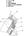
このとき、図3に示すように第1の送風手段である送風ファンの34の送風口40の近傍に第2の送風手段である送風ファン42の吹き出し部43を設けて、第2の循環風路41内に設けた第2の送風手段である送風ファン42よりラビリンス部27から流出する乾燥用空気と対向するようにラビリンス部27の外側より風量q2を送風する。
At this time, as shown in FIG. 3, a blowing
ここで、風量q1とq2を同程度に設定することで、乾燥用空気の一部がラビリンス部27を通過することを抑え、また、風量q2の一部がラビリンス部27を通過して内槽25内へ流れないようにしている。つまり、第2の送風手段の風量q2は第1の送風手段の風量Qより少ない風量で送風している。
Here, by setting the air volumes q1 and q2 to be approximately the same, it is possible to prevent a part of the drying air from passing through the
第2の送風手段である送風ファン42より送風された空気により、第1の送風手段である送風ファン34により送風した乾燥用空気は、ラビリンス部27からの流出を抑えられ内槽25内へ流れる。内槽25内へ流れた乾燥用空気は衣類24と接触して衣類24から水分を奪い衣類24を乾燥する。
Due to the air blown from the
以上のように、多くの衣類24を内槽25内で乾燥するときや、脱水終了後に衣類24の内壁に衣類が張り付いている状態のときなど、送風口40近傍に衣類24がある場合、第2の送風手段である送風ファン42により、ラビリンス部27から流出する乾燥用空気と対向するようにラビリンス部27の外側より送風することで、第1の送風手段である送風ファン34により送風した乾燥用空気の一部が内槽25内に流れず内槽25と外槽23の間を通過することを抑えることができ、衣類24の乾燥効率を向上して乾燥時間を短縮し、省エネ性を向上することができる。
As described above, when
また、外槽23の前方と後方を接続するように第2の循環風路41を設け、第2の送風手段を第2の循環風路41に設けているので、衣類24と接触した後の乾燥用空気によりラビリンス部27から流出する乾燥用空気を抑えることができ、衣類24の乾燥効率を向上して乾燥時間を短縮し、省エネ性を向上することができる。
Moreover, since the 2nd
また、第2の送風手段は、外槽23内への吹き出し部43を第1の循環風路36の外槽23内への送風口40の近傍に設ける構成としているので、さらにラビリンス部27から流出する乾燥用空気を抑えることができ、衣類24の乾燥効率を向上して乾燥時間を短縮し、省エネ性を向上することができる。
Moreover, since the 2nd ventilation means is set as the structure which provides the blowing
また、第1の送風手段により送風された乾燥用空気がラビリンス部27を通過する風量q1と、第2の送風手段により送風された風量q2がラビリンス部27でバランスするように設定したので、ラビリンス部27から流出する乾燥用空気を抑えるとともに、衣類24と接触した後の乾燥用空気が除湿加熱されずに再び内槽25内へ流れることを抑え、衣類24の乾燥効率を向上して乾燥時間を短縮し、省エネ性を向上することができる。
Further, since the air volume q1 of the drying air blown by the first blower means passes through the
また、第2の送風手段の風量q2を第1の送風手段の風量Qより少なくしたので、ラビリンス部27から流出する乾燥用空気を抑えるとともに、衣類24と接触した後の乾燥用空気が除湿加熱されずに再び内槽25内へ流れることを抑え、衣類24の乾燥効率を向上して乾燥時間を短縮し、省エネ性を向上することができる。
Further, since the air volume q2 of the second air blowing means is smaller than the air volume Q of the first air blowing means, the drying air flowing out from the
(実施の形態2)
図4は、本発明の第2の実施の形態における洗濯乾燥機の断面図である。なお、第1の実施の形態と同一構成要件は同一符号を付して詳細な説明は省略する。
(Embodiment 2)
FIG. 4 is a sectional view of the washing / drying machine according to the second embodiment of the present invention. The same constituent elements as those in the first embodiment are denoted by the same reference numerals, and detailed description thereof is omitted.
第2の送風手段である送風ファン42の吹き出し部43をラビリンス部27の外側に接続し、吸い込み口44を開放とした構成としている。
The blowing
以上のような構成において、次に、この動作について説明する。一連の洗濯、すすぎ、脱水、乾燥の各工程は、実施の形態1と同様なので、相違点のみ説明する。 Next, the operation of the above configuration will be described. Since a series of washing, rinsing, dehydration, and drying steps are the same as in the first embodiment, only the differences will be described.
乾燥工程において、送風ファン34が作動し、放熱器37の放熱により加熱された乾燥用空気が第1の循環風路36を通って送風口40から外槽23内へ送風している。外槽23内へ送風された乾燥用空気の主流は内槽25内に入り、衣類24と接触して衣類24から水分を奪い衣類24を乾燥する。衣類24の水分を奪った乾燥用空気は外槽排気口35を通って再び送風ファン34へと戻り、循環する。
In the drying process, the
また、乾燥工程初期の脱水終了後に内壁に衣類24が張り付いている状態のときや内槽25内に多くの衣類24が入っていて、送風口40を塞ぐように衣類24が存在するときは、外槽23内へ送風した乾燥用空気の一部が、外槽23の内底面と内槽5の外底面とに複数の環状突起を設けて構成したラビリンス部27を通過して、外槽23と内槽25の間を通過して、外槽排気口35へ流出しようとする。
Further, when the
このとき、第2の送風手段である送風ファン42よりラビリンス部27から流出する乾燥用空気と対向するようにラビリンス部27の外側より送風する。第2の送風手段である送風ファン42の吸い込み口44は、開放状態のため外気を第1の循環風路36内へ送風することになるが、第1の循環風路は閉じた循環風路なので、第2の送風手段である送風ファン42からは空気は送風されずに、ラビリンス部27の外側の圧力を高めることになる。この圧力を高めることにより、送風口40近傍に衣類24がある場合、第1の送風手段である送風ファン34により送風した乾燥用空気の一部が内槽25内に流れず内槽25と外槽23の間を通過することを抑えることができ、衣類24の乾燥効率を向上して乾燥時間を短縮し、省エネ性を向上することができる。
At this time, air is blown from the outside of the
以上のように、本発明にかかる洗濯乾燥機は、ラビリンス部から流出する乾燥用空気を抑えることができ、衣類の乾燥効率を向上して乾燥時間を短縮し、省エネ性を向上することができるので、ヒータ式など乾燥機能を備えた洗濯乾燥機に有用である。 As described above, the washing / drying machine according to the present invention can suppress the drying air flowing out from the labyrinth, improve the drying efficiency of the clothes, shorten the drying time, and improve the energy saving performance. Therefore, it is useful for a washing and drying machine having a drying function such as a heater type.
21 本体
23 外槽
25 内槽
26 駆動モータ(駆動手段)
27 ラビリンス部
34 送風ファン(第1の送風手段)
36 第1の循環風路
37 放熱器(加熱手段)
38 吸熱器(除湿手段)
40 送風口
41 第2の循環風路
42 送風ファン(第2の送風手段)
43 吹き出し部
44 吸い込み口
21
27
36 1st
38 Heat absorber (dehumidifying means)
40
43
Claims (6)
Priority Applications (1)
| Application Number | Priority Date | Filing Date | Title |
|---|---|---|---|
| JP2007186620A JP2009022402A (en) | 2007-07-18 | 2007-07-18 | Washing and drying machine |
Applications Claiming Priority (1)
| Application Number | Priority Date | Filing Date | Title |
|---|---|---|---|
| JP2007186620A JP2009022402A (en) | 2007-07-18 | 2007-07-18 | Washing and drying machine |
Publications (1)
| Publication Number | Publication Date |
|---|---|
| JP2009022402A true JP2009022402A (en) | 2009-02-05 |
Family
ID=40394825
Family Applications (1)
| Application Number | Title | Priority Date | Filing Date |
|---|---|---|---|
| JP2007186620A Pending JP2009022402A (en) | 2007-07-18 | 2007-07-18 | Washing and drying machine |
Country Status (1)
| Country | Link |
|---|---|
| JP (1) | JP2009022402A (en) |
-
2007
- 2007-07-18 JP JP2007186620A patent/JP2009022402A/en active Pending
Similar Documents
| Publication | Publication Date | Title |
|---|---|---|
| JP4531414B2 (en) | Washing and drying machine | |
| WO2007060796A1 (en) | Drum-type washer/dryer | |
| JP4444016B2 (en) | Clothes dryer | |
| KR100437790B1 (en) | Washing machine having drying function | |
| JP2005304987A (en) | Clothes dryer | |
| US20060086001A1 (en) | Washing machine combined with dryer | |
| JP2007000386A (en) | Clothes dryer | |
| JP2007319458A (en) | Washing and drying machine | |
| JP2005177505A (en) | Washing machine cum drying machine | |
| JP6842261B2 (en) | Clothes dryer | |
| JP4876695B2 (en) | Washing and drying machine | |
| JP4552748B2 (en) | Washing and drying machine | |
| JP7470065B2 (en) | Washing and drying machine | |
| JP4507966B2 (en) | Washing and drying machine | |
| JP2006204656A (en) | Washing and drying machine | |
| JP4396483B2 (en) | Washing and drying machine | |
| JP2007068871A (en) | Clothes dryer | |
| WO2014024346A1 (en) | Washer/dryer | |
| KR100733298B1 (en) | Drying Washer | |
| JP2009022402A (en) | Washing and drying machine | |
| JP2023165561A (en) | Washing and drying machine | |
| JP4353061B2 (en) | Washing and drying machine | |
| JP3990325B2 (en) | Washing and drying machine | |
| JP4466524B2 (en) | Washing and drying machine | |
| JP4693686B2 (en) | Washing and drying machine |