JP2009041602A - Control device and control method for automatic transmission - Google Patents
Control device and control method for automatic transmission Download PDFInfo
- Publication number
- JP2009041602A JP2009041602A JP2007204868A JP2007204868A JP2009041602A JP 2009041602 A JP2009041602 A JP 2009041602A JP 2007204868 A JP2007204868 A JP 2007204868A JP 2007204868 A JP2007204868 A JP 2007204868A JP 2009041602 A JP2009041602 A JP 2009041602A
- Authority
- JP
- Japan
- Prior art keywords
- fail
- transmission
- failure
- automatic transmission
- safe
- Prior art date
- Legal status (The legal status is an assumption and is not a legal conclusion. Google has not performed a legal analysis and makes no representation as to the accuracy of the status listed.)
- Withdrawn
Links
Images




Landscapes
- Control Of Transmission Device (AREA)
Abstract
【課題】
自動MTシステムにおいて、構成部品毎の故障検出と故障した構成部品毎のフェールセーフ制御を実行したとき、故障部位特定の誤判定等により故障部位の拡大が懸念される。また、構成部品毎のフェールセーフ制御を備えることは、制御仕様の複雑化,開発工数の増大を招く。
【解決手段】
構成部品の故障状態を判定するn個の故障判定手段と、故障部位から想定される周辺・関連部位の故障発生であっても、暴走・エンスト・急減速が発生せず、また2重故障へ起因しない運転状態を確保することが可能な予め統合化,グループ化されたn個の故障判定手段よりも少ないm個のフェールセーフモード実行手段を備え、故障発生が検出・判定されたときに、m個のフェールセーフモードのうち、故障部位に対応するフェールセーフモードを選択する。
【選択図】図1【Task】
In the automatic MT system, when failure detection for each component part and fail-safe control for each failed component part are executed, there is a concern about expansion of the failure part due to erroneous determination of failure part identification. In addition, providing fail-safe control for each component causes complicated control specifications and increased development man-hours.
[Solution]
N failure judgment means to judge the failure status of components and runaway / engine stall / sudden deceleration will not occur even if there is a fault in the surrounding / related part assumed from the fault part. It is provided with m fail-safe mode execution means fewer than n failure judgment means integrated and grouped in advance, which can ensure a non-originating operation state, and when a failure occurrence is detected and judged, m The fail-safe mode corresponding to the failed part is selected from the fail-safe modes.
[Selection] Figure 1
Description
本発明は、自動車における自動変速機制御システムの構成デバイスの故障時に発動するフェールセーフ制御方法及びその制御装置に関する。 The present invention relates to a fail-safe control method that is activated when a component device of an automatic transmission control system in an automobile fails, and a control apparatus therefor.
手動変速機の自動車はトルクコンバータを用いた変速機を搭載するものに比べ燃費がすぐれており、最近では、手動変速機の機構を用いてクラッチとギアチェンジを自動化したシステムである自動MT(自動化マニュアルトランスミッション)が開発されている。従来型の手動変速機と同様にエンジンと変速機との間に駆動力を断・接可能な摩擦クラッチを1つ有する初期の自動MT(自動化マニュアルトランスミッション)では、アップシフト,ダウンシフトといった変速段切替の際に、上記摩擦クラッチの解放・締結操作を伴うため、加速度変動が発生し、乗員に違和感を与えることがある。そこで、従来の自動MT(自動化マニュアルトランスミッション)に対して、変速中のトルク伝達を行うための第2の摩擦式クラッチ(アシストクラッチ)を、変速機の入力軸と出力軸との間に設けた自動変速機が提案されている(特許文献1参照)。このアシストクラッチを設けた自動MT(自動化マニュアルトランスミッション)における変速時の制御では、変速開始時に噛合い式クラッチが締結されている状態からアシストクラッチを押し付けることでアシストクラッチが滑りながらトルク伝達を行い、所定のトルク伝達が実現した状態で、噛合い式クラッチを解放する。このように、変速動作の開始において噛合い式クラッチからアシストクラッチに変更することで変速中のトルク伝達を実現している。 Automobiles with manual transmissions have better fuel efficiency than those equipped with transmissions that use torque converters. Recently, automatic MT (automated) is a system that uses a manual transmission mechanism to automate clutch and gear changes. Manual transmission) has been developed. In the initial automatic MT (automated manual transmission) that has one friction clutch that can connect / disconnect the driving force between the engine and the transmission as in the conventional manual transmission, the shift stages such as upshift and downshift When the switching is performed, the friction clutch is released / engaged, so that acceleration fluctuations may occur, which may cause the passenger to feel uncomfortable. Therefore, a second friction clutch (assist clutch) for transmitting torque during shifting is provided between the input shaft and the output shaft of the transmission, compared to the conventional automatic MT (automated manual transmission). An automatic transmission has been proposed (see Patent Document 1). In the control at the time of shifting in the automatic MT (automated manual transmission) provided with the assist clutch, torque transmission is performed while the assist clutch slips by pressing the assist clutch from the state in which the meshing clutch is engaged at the start of shifting, In a state where predetermined torque transmission is realized, the meshing clutch is released. In this way, torque transmission during shifting is realized by changing from the mesh clutch to the assist clutch at the start of the shifting operation.
また、エンジンからの駆動力伝達軸に対し、複数の入力軸を持つとともに摩擦式クラッチを有し、各軸に設けた噛合い式クラッチにより締結された変速ギア段によりトルク伝達を行う所謂ツインクラッチ自動MTが近年実用化され始めている。 Also, a so-called twin clutch that has a plurality of input shafts and a friction clutch with respect to the driving force transmission shaft from the engine, and transmits torque by a transmission gear stage fastened by a meshing clutch provided on each shaft. Automatic MT has begun to be put into practical use in recent years.
このツインクラッチ自動MTでは、例えば各軸に奇数ギア段,偶数ギア段が割付けられており、所定ギア段にて走行中は所定ギア段に該当する軸の摩擦式クラッチ及び噛合い式クラッチが締結することでトルク伝達を行う。所定ギア段に該当しない軸は摩擦式クラッチが解放状態であり他方の軸にてトルク伝達している状態においても拘束されることなく噛合い式クラッチの操作(選択ギア段の切替)を行うことができる。よって変速開始前に予め予測されるギア段を選択しておくことが可能となり、変速中は噛合い式クラッチは締結させたまま、所望のタイミングにより、これまで締結していた摩擦式クラッチを解放するとともに、解放状態にあった摩擦式クラッチを締結させて伝達トルクの架け替えを行うことにより、トルク伝達を行いながら変速(ギア段切替)を実現するものである。 In this twin clutch automatic MT, for example, odd-numbered gears and even-numbered gears are assigned to each shaft, and the friction clutch and the meshing clutch of the shaft corresponding to the predetermined gear are engaged while traveling at the predetermined gear. To transmit torque. A shaft that does not correspond to a predetermined gear stage performs the operation of the meshing clutch (switching of the selected gear stage) without being restricted even when the friction clutch is in the released state and the torque is transmitted on the other shaft. Can do. Therefore, it is possible to select a gear stage that is predicted in advance before the start of gear shifting, and while the gear clutch is engaged during gear shifting, the friction clutch that has been engaged is released at a desired timing. At the same time, by engaging the friction clutch in the disengaged state and replacing the transmission torque, shifting (gear stage switching) is realized while torque is being transmitted.
これらの自動MTシステムは、従来運転者が行っていた変速・発進時の変速機操作(クラッチ解放・締結,ギアシフトレバー切替等)を自動化し、更に運転フィーリングを向上させるため、複数のセンサ,アクチュエータ,メカリンク機構等が追加となり、従来手動変速機に比べ、部品点数は必然的に増えてしまう。部品点数が増加することで、安全性の面では、構成部品の故障発生確率が増加するため、個々のセンサ・アクチュエータ,メカ機構といった構成部品に対し、それぞれに故障検出手段(診断制御)及び故障発生時のフェールセーフ制御を個々に備える必要がある。 These automatic MT systems automate transmission operations (clutch disengagement / engagement, gear shift lever switching, etc.) at the time of shifting / starting, which have been conventionally performed by the driver, and further improve the driving feeling. An actuator, a mechanical link mechanism, and the like are added, and the number of parts inevitably increases as compared with the conventional manual transmission. As the number of parts increases, the probability of component failure increases in terms of safety. Therefore, failure detection means (diagnostic control) and failure for each component such as individual sensors / actuators and mechanical mechanisms It is necessary to individually provide fail-safe control at the time of occurrence.
センサ,アクチュエータ,メカ機構といった構成部品点数の増加に伴い、故障発生確率及び故障モード(故障部位)が増大するため、個々の構成部品・故障モードに対して故障検出手段が必要となってくる。例えばセンサの場合、センサからの入力電圧値が所定電圧範囲外の状態が継続すれば、センサ故障及びセンサハーネス系の断線・ショート故障と判定することができる。また、アクチュエータにおいては指令要求に対する実動作状態をセンサ値等で間接的に検出し、期待値と実値を比較することにより機能故障を判定することができる。 As the number of components such as sensors, actuators, and mechanical mechanisms increases, failure occurrence probability and failure mode (failure site) increase, so that failure detection means is required for each component / failure mode. For example, in the case of a sensor, if the state where the input voltage value from the sensor is outside the predetermined voltage range continues, it can be determined that the sensor is faulty and the sensor harness system is disconnected or short-circuited. Further, in the actuator, it is possible to determine the functional failure by indirectly detecting the actual operation state with respect to the command request by the sensor value or the like and comparing the expected value with the actual value.
このように部品点数増加に伴い故障モードが増加するため、個々のセンサ,アクチュエータ,メカ機構に対して故障検出手段を備える必要があり、更には故障検出(発生)時における車両挙動,運転性を確保するため、一般的には各故障部位に対応したフェールセーフ制御・動作を備える。例えば、故障部位が特定ギア段のシンクロ締結ができない故障状態であれば、そのギア段以外のギア段を用いて、変速・発進を行うことが考えられるように、故障部位以外の正常なセンサ・アクチュエータ,メカ機構で出来る限りの運転性を維持することが可能である。しかし、故障部位と同数のフェールセーフ制御が必要となるため、変速機制御を構築する面からみれば、制御仕様の複雑化,開発・確認工数の増大に起因するため望ましくない。 As the number of parts increases in this way, failure modes increase, so it is necessary to provide failure detection means for each sensor, actuator, and mechanical mechanism. Furthermore, vehicle behavior and drivability during failure detection (occurrence) can be improved. In order to ensure, generally, fail-safe control / operation corresponding to each failure part is provided. For example, if the failure part is in a failure state where a specific gear stage cannot be synchronized, gears other than that gear stage may be used to perform gear shifting / starting. It is possible to maintain the operability as much as possible with actuators and mechanical mechanisms. However, since the same number of fail-safe controls as failure parts are required, from the viewpoint of constructing transmission control, it is not desirable because it is caused by complicated control specifications and an increase in development / confirmation man-hours.
また、特定ギア段のシンクロ締結ができない状態を故障と判定した場合、真に特定ギア段のシンクロメッシュ機能が磨耗・故障している状態とは限定できない場合も考えられる。例えば上述のツインクラッチ自動MTにおいては、シンクロ締結できない軸に備えられたエンジン出力軸と変速機入力軸間の摩擦クラッチが締結状態で故障しており、エンジン駆動力が入力軸に付加されているため、シンクロメッシュ機能による回転数同期ができない状況にある可能性も考えられる。この場合、クラッチの故障検出手段により正常状態であることが確定できる状態にあれば、真にシンクロ機能故障等の故障部位限定が可能となるが、限られたセンサ検出値、及び車両運転状況下においては、各部品が正常である事が同一タイミング・運転状態では判断できず、故障部位の特定には至らないことが考えられる。クラッチが故障しているためにギア締結ができない状態にも関わらず、特定ギア段のシンクロ故障として、上述のような特定ギア段以外のギア段で走行維持とするフェールセーフ制御を実行すると、故障判定したギア段と同一軸に存在するギア段を選択・締結操作を行った際に、クラッチ締結状態にあるためエンスト・急減速が発生してしまう可能性がある。また、故障部位の誤判定状態にも関わらず、上記のフェールセーフ制御を継続することで、その他部位・部品の故障いわゆる2重故障を引き起こすことが懸念される。 In addition, when it is determined that a state in which the specific gear stage cannot be synchronized is determined to be a failure, there may be a case where it cannot be limited to a state in which the synchromesh function of the specific gear stage is truly worn or broken. For example, in the above-described twin clutch automatic MT, the friction clutch between the engine output shaft and the transmission input shaft provided on the shaft that cannot be synchronized is broken in the engaged state, and the engine driving force is applied to the input shaft. Therefore, there is a possibility that the number of revolutions cannot be synchronized by the synchromesh function. In this case, if the clutch failure detection means can determine that it is in a normal state, it is possible to limit the failure part such as a synchro function failure truly, but under limited sensor detection values and vehicle driving conditions. In this case, it is conceivable that the fact that each component is normal cannot be determined at the same timing and operation state, and the failure part cannot be specified. When fail-safe control is performed to maintain traveling at a gear stage other than the above-mentioned specific gear stage as a sync fault of a specific gear stage even if the gear cannot be engaged due to a clutch failure, When a gear stage that exists on the same axis as the determined gear stage is selected and engaged, the engine may be engaged and sudden deceleration may occur because the clutch is engaged. In addition, despite the erroneous determination state of the failed part, there is a concern that failure of other parts / parts, that is, a double failure may be caused by continuing the above fail-safe control.
本発明の目的は、構成部品点数の増加に伴い、故障部位の特定が困難または誤判定が懸念されることに鑑みてなされ、故障検出(発生)時にエンスト・急減速・暴走の発生を回避し、また2重故障といった故障部位の拡大を抑制する自動変速機のフェールセーフ制御方法を提供することにある。 An object of the present invention is to avoid the occurrence of engine stall / sudden deceleration / runaway at the time of failure detection (occurrence) when the number of components increases and it is difficult to identify a faulty part or there is a concern about erroneous determination. Another object of the present invention is to provide a fail-safe control method for an automatic transmission that suppresses the expansion of a failure part such as a double failure.
前記目的を達成すべく、本発明の自動変速機のフェールセーフ制御方法は、変速機に入力される各センサ検出値,運転状態情報から構成部品の故障状態を判定するn個の故障判定手段,故障部位から想定される周辺・関連部位の故障発生であっても、暴走・エンスト・急減速が発生せず、また2重故障へ起因しない運転状態を確保することが可能な予め統合化,グループ化された前記n個の故障判定手段よりも少ないm個のフェールセーフモード実行手段を備え、前記故障判定手段により故障発生が検出・判定されたときに、故障部位毎に予め設定されたm個のフェールセーフモードのうち、故障判定された故障部位に対応するフェールセーフモードを選択するフェールセーフ選択手段を有し、選択されたフェールセーフモードに応じて、クラッチ・シフト・潤滑動作を実現する各アクチュエータを駆動する。 In order to achieve the above object, a failsafe control method for an automatic transmission according to the present invention includes n failure determination means for determining a failure state of a component from each sensor detection value and operation state information input to the transmission. Pre-integrated and grouped to ensure that there is no runaway, engine stall, or sudden deceleration even if there is a fault in the surrounding or related area that is expected from the faulty part, and that it is possible to ensure an operating state that does not result from a double fault. M fail-safe mode execution means that are fewer than the n failure determination means, and when a failure occurrence is detected and determined by the failure determination means, m failure presets are set for each failure portion. Among the failsafe modes, there is a failsafe selection means for selecting a failsafe mode corresponding to the faulty part that has been determined to be faulty, and according to the selected failsafe mode, Driving each actuator to achieve the pitch shift lubrication operation.
特定した故障部位によらず、その故障部位周辺・関連の部位故障から想定される車両への影響度合いから予め統合化・グループ化されたフェールセーフモードを実行することにより、フェールセーフモード実行中における暴走・エンスト・急減速を回避し、また2重故障等の故障部位拡大を抑制することが可能となる。さらには、n個の故障判定手段毎の異なるフェールセーフ制御を備える場合に比べ、制御仕様の簡略化,開発・動作確認工数の低減が実現できる。 Regardless of the specified failure part, runaway during fail-safe mode execution by executing the fail-safe mode that is integrated and grouped in advance based on the degree of influence on the vehicle that is assumed from the surrounding part of the failure part and related part failure It is possible to avoid engine stalls and sudden deceleration, and to suppress the expansion of failure sites such as double failures. Furthermore, compared with the case where different fail-safe controls are provided for each of the n failure determination means, the control specifications can be simplified and the number of development / operation check man-hours can be reduced.
以下、本発明の実施の形態を図面に基づき詳細に説明する。 Hereinafter, embodiments of the present invention will be described in detail with reference to the drawings.
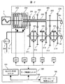
図1は、本発明に係る自動変速機のフェールセーフ制御置の一実施の形態を示す。パワートレーン制御ユニット100内には、変速機に入力される各センサ検出値,運転状態情報から構成部品の故障状態を判定する1〜n個の故障判定手段(a1〜a3),故障部位から想定される周辺・関連部位の故障発生であっても、暴走・エンスト・急減速が発生せず、また2重故障へ起因しない運転状態を確保することが可能な予め統合化,グループ化された前記n個の故障判定手段よりも少ないm個のフェールセーフモードA〜D実行手段(a5〜a8にて代表)を備え、前記故障判定手段(a1〜a3)により故障発生が検出・判定されたときに、故障部位毎に予め設定されたm個のフェールセーフモードのうち、故障判定された故障部位に対応するフェールセーフモードを選択するフェールセーフ選択手段(a8)を有し、選択されたフェールセーフモードに応じて、各クラッチ・シフト・潤滑動作を実現する変速機構成アクチュエータ群(a9)を駆動する。
FIG. 1 shows an embodiment of a fail-safe control device for an automatic transmission according to the present invention. In the power
これにより、特定した故障部位によらず、その故障部位周辺・関連の部位故障から想定される車両への影響度合いから予め統合化・グループ化されたフェールセーフモードを実行することにより、フェールセーフモード実行中における暴走・エンスト・急減速を回避し、また2重故障等の故障部位拡大を抑制することが可能となる。 As a result, the fail-safe mode is being executed by executing the fail-safe mode that is integrated and grouped in advance based on the degree of influence on the vehicle that is assumed from the surrounding failure of the failure part and related part failure, regardless of the specified failure part. It is possible to avoid runaway, engine stall, and sudden deceleration at, and to suppress the expansion of failure sites such as double failures.
さらには、n個の故障判定手段毎の異なるフェールセーフ制御を備える場合に比べ、制御仕様の簡略化,開発・動作確認工数の低減が実現できる。 Furthermore, compared with the case where different fail-safe controls are provided for each of the n failure determination means, the control specifications can be simplified and the number of development / operation check man-hours can be reduced.
ここでは、フェールセーフ実行手段として、モードA〜Dの4つに統合化された実行手段を例としたが、n個の診断判定手段よりも少ないm個の範囲での故障部位に関連・関係する部位を想定した車両への影響度合いより統合化,グループ化される形態であればよい。 Here, as the fail-safe execution means, the execution means integrated into the four modes A to D is taken as an example. However, the relation / relationship is related to the failure site in m ranges smaller than n diagnosis determination means. Any form may be used as long as it is integrated and grouped based on the degree of influence on the vehicle assuming the part to be performed.
図7に図1のフェールセーフモード選択手段の処理フローチャートの一例を示す。 FIG. 7 shows an example of a processing flowchart of the fail safe mode selection means of FIG.
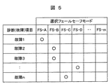
図1の故障判定手段(a1〜a3)が故障判定処理c1に該当する。故障判定処理c1において故障発生(検出)したか否かをc2処理にて判定を行い、未検出状態のときは、c8処理によりフェールセーフモード未選択として処理を終了する。c2処理にて故障検出時には、処理c3において、故障部位毎に予め設定された選択フェールセーフモード表に従い、未選択も含めた何れかのフェールセーフモードを選択する(処理c5〜c8)。この処理フローにより故障検出時に予め故障部位毎に設定されたフェールセーフモードが選択され、選択されたフェールセーフモードに応じて、各アクチュエータ駆動が開始される。図5に故障部位毎の選択フェールセーフモード表の一例を示す。 The failure determination means (a1 to a3) in FIG. 1 corresponds to the failure determination process c1. In the failure determination process c1, whether or not a failure has occurred (detected) is determined by the c2 process. When the failure is not detected, the fail safe mode is not selected by the c8 process and the process is terminated. When a failure is detected in the c2 process, in the process c3, any fail-safe mode including unselected is selected according to the selected fail-safe mode table preset for each failed part (processes c5 to c8). With this processing flow, a fail-safe mode set in advance for each failed part at the time of failure detection is selected, and driving of each actuator is started according to the selected fail-safe mode. FIG. 5 shows an example of the selected fail-safe mode table for each failure part.
故障部位(診断項目)毎にその部位故障が発生した際に実行するフェールセーフモードを予め設定しておき、パワートレーン制御ユニット100内に有する不揮発性メモリ等に記憶し、故障発生時において図7のフェールセーフモード選択処理c3では、本表のデータを検索することによりフェールセーフモードを選択する。予め設定されるフェールセーフモード表はその記憶値に限定するものではなく、演算式により、同様の選択が実現できる構成であればよい。
A fail-safe mode to be executed when a failure occurs in each failure part (diagnostic item) is set in advance and stored in a non-volatile memory or the like in the power
図5では診断(故障)項目による選択フェールセーフモード表を一例としたが、項目のパラメータはフェールセーフモードを選択・設定する上で最良の項目であればよい。 In FIG. 5, the selection failsafe mode table by diagnosis (failure) item is taken as an example, but the parameter of the item may be the best item for selecting and setting the failsafe mode.
図2に、本発明に係る制御装置の一実施の形態を示すシステム構成例のスケルトン図を示す。 FIG. 2 shows a skeleton diagram of a system configuration example showing an embodiment of a control device according to the present invention.
駆動力源であるエンジン7,エンジン7の回転数を計測するエンジン回転数センサ(図示しない),エンジントルクを調節する電子制御スロットル(図示しない),吸入空気量に見合う燃料量を噴射するための燃料噴射装置(図示しない)が設けられており、エンジン制御ユニット101により、吸入空気量,燃料量,点火時期等を操作することで、エンジン7のトルクを高精度に制御することができるようになっている。燃料噴射装置には、燃料が吸気ポートに噴射される吸気ポート噴射方式あるいはシリンダ内に直接噴射される筒内噴射方式があるが、エンジンに要求される運転域(エンジントルク,エンジン回転数で決定される領域)を比較して燃費が低減でき、かつ排気性能が良い方式のエンジンを用いるのが有利である。駆動力源としては、ガソリンエンジンのみならず、ディーゼルエンジン,天然ガスエンジンや、電動機などでも良い。
自動変速機51には、第1クラッチ208,第2クラッチ209,変速機第1入力軸241,変速機第2入力軸243,変速機出力軸242,第1ドライブギア201,第2ドライブギア202,第3ドライブギア203,第4ドライブギア204,第5ドライブギア205,第1ドリブンギア211,第2ドリブンギア212,第3ドリブンギア213,第4ドリブンギア214,第5ドリブンギア215,第1噛合い伝達機構221,第2噛合い伝達機構222,第3噛合い伝達機構223,回転センサ31,回転センサ32,回転センサ33が設けられている。
The
本構成例はツインクラッチで構成している変速機を示している。 This configuration example shows a transmission configured with a twin clutch.
すなわち、第1クラッチ208の係合によって、エンジン7のトルクを変速機第1入力軸241に伝達し、また第2クラッチ209の係合によって、エンジン7のトルクを変速機第2入力軸243に伝達する。変速機第2入力軸243は中空になっており、変速機第1入力軸241は、変速機第2入力軸243の中空部分を貫通し、変速機第2入力軸243に対し回転方向への相対運動が可能な構成となっている。
That is, the torque of the
変速機第2入力軸243には、第1ドライブギア201と第3ドライブギア203と第5ドライブギア205が固定されており、変速機第1入力軸241に対しては、回転自在となっている。また、変速機第1入力軸241には、第2ドライブギア202と第4ドライブギア204が固定されており、変速機第2入力軸243に対しては、回転自在となっている。
The
第1クラッチ208の係合,解放は、第1クラッチアクチュエータ254によって行われ、第2クラッチ209の係合,解放は、第2クラッチアクチュエータ255によって行われる。
Engagement / release of the
また、変速機第1入力軸241の回転数を検出する手段として、センサ31が設けられており、変速機第2入力軸243の回転数を検出する手段として、センサ33が設けられている。
A
一方、変速機出力軸242には、第1ドリブンギア211,第2ドリブンギア212,第3ドリブンギア213,第4ドリブンギア214,第5ドリブンギア215が設けられている。第1ドリブンギア211,第2ドリブンギア212,第3ドリブンギア213,第4ドリブンギア214,第5ドリブンギア215は変速機出力軸242に対して回転自在に設けられている。
On the other hand, the
また、変速機出力軸242の回転数を検出する手段として、センサ32が設けられている。
A
また、第1ドリブンギア211と第3ドリブンギア213の間には、第1ドリブンギ211を変速機出力軸242に係合させたり、第3ドリブンギア213を変速機出力軸242に係合させる、第1噛合い伝達機構221が設けられている。
Further, between the first driven
また、第2ドリブンギア212と第4ドリブンギア214の間には、第2ドライブギア212を変速機出力軸242に係合させたり、第4ドリブンギア214を変速機出力軸242に係合させる、第3噛合い伝達機構223が設けられている。
Further, between the second driven
また、第5ドリブンギア215には、第5ドリブンギア215を変速機出力軸242に係合させる、第2噛合い伝達機構222が設けられている。
The fifth driven
ここで、前記噛合い伝達機構221,222,223は、摩擦伝達機構を備え、摩擦面を押しつけることによって回転数を同期させて噛合いを行う同期噛合い式を用いることが望ましい。
Here, it is desirable that the
シフトアクチュエータ251によって、第1噛合い伝達機構221の位置を移動し、第1ドリブンギア211または、第3ドリブンギア213と係合させることで、変速機第2入力軸243の回転トルクを、第1噛合い伝達機構221を介して変速機出力軸242へと伝達することができる。
The position of the first
また、シフトアクチュエータ253によって、第3噛合い伝達機構223の位置を移動し、第2ドリブンギア212または、第4ドリブンギア214と係合させることで、変速機第1入力軸241の回転トルクを、第3噛合い伝達機構223を介して変速機出力軸242へと伝達することができる。
Further, the
また、シフトアクチュエータ252によって、第2噛合い伝達機構222の位置を移動し、第5ドリブンギア215と係合させることで、変速機第2入力軸243の回転トルクを、第2噛合い伝達機構222を介して変速機出力軸242へと伝達することができる。
Further, the position of the second
このように第1ドライブギア201,第2ドライブギア202,第3ドライブギア203,第4ドライブギア204,第5ドライブギア205から、第1ドリブンギア211,第2ドリブンギア212,第3ドリブンギア213,第4ドリブンギア214,第5ドリブンギア215を介して変速機出力軸242に伝達された変速機第1入力軸241,変速機第2入力軸243の回転トルクは、変速機出力軸242に連結されたディファレンシャルギア(図示しない)を介して車軸(図示しない)に伝えられる。
Thus, from the
第1クラッチ208の係合,解放動作により伝達トルクを制御する第1クラッチアクチュエータ254,第2クラッチ209の係合,解放動作により伝達トルクを制御する第2クラッチアクチュエータ255は、モータ制御ユニット104によって、各アクチュエータに設けられたモータ(図示せず)の電流を制御することで各クラッチの伝達トルクの制御を行っている。
The first
また、モータ制御ユニット104によって、シフトアクチュエータ251,252,253に設けられたモータ(図示せず)の電流を制御することによって、第1噛合い伝達機構221,第2噛合い伝達機構222,第3噛合い伝達機構223のいずれかを動作させる荷重またはストローク位置(シフト位置)を制御できるようになっている。
Further, the
そして、モータ制御ユニット104とエンジン制御ユニット101は、パワートレーン制御ユニット100によってコントロールされている。パワートレーン制御ユニット100,エンジン制御ユニット101,モータ制御ユニット104は、通信手段103によって相互に情報を送受信する。
The
また本実施例においては、第1クラッチアクチュエータ254,第2クラッチアクチュエータ255,シフトアクチュエータ251,252,253にはモータアクチュエータを用いているが、油圧源と油圧シリンダ及び電磁弁等により構成する油圧アクチュエータによって構成してもよい。同様にモータ制御ユニット104も油圧制御ユニットに置き換わることになる。
In this embodiment, motor actuators are used as the first
第1クラッチ208,第2クラッチ209が湿式クラッチで構成されるときにはパワートレーン制御ユニット100により駆動される電動潤滑油ポンプ260から第1クラッチ208,第2クラッチ209に潤滑油が供給される。ここでは電動ポンプにより供給する方式を図示したが、供給及び流量制御方式を限定するものではなく、エンジン駆動ポンプ,流量レギュレータ等でもよく、湿式クラッチに潤滑油を供給可能であればよい。
When the
図3に、本実施例の電気的制御系統を説明するブロック図の一例である。本例では自動変速機制御装置として、エンジン制御ユニット(ECU:Electronic Control Unit)101,パワートレーン制御ユニット(ECU)100の2つのECUで構成されており、各ECU間は通信回線を介して必要な情報をやり取りする。これらのECU100,101は、何れもマイクロコンピュータを含んで構成されており、RAMの一時記憶機能を利用しつつROMに予め記憶されたプログラムに従って信号処理を行う。なお、記憶機能に書換え可能なROMを使用し、必要に応じて書き換えながら使用することも可能である。
エンジン用ECU101には、イグニッションスイッチ71,エンジン回転数センサ72,出力軸回転数センサ73,アクセル開度センサ74,空気量センサ75,吸気温センサ76,冷却水温センサ77,ブレーキスイッチ78などが接続され、それぞれイグニッションスイッチ71の操作位置,エンジン回転数Ne,出力軸回転数No,アクセル開度APS,吸入空気量Q,吸気温Ta ,エンジン冷却水温Tw ,ブレーキスイッチ78の操作位置などを表す信号が供給されるようになっており、それ等の信号に従ってスタータ79を回転駆動してエンジン7を始動したり、燃料噴射弁80の燃料噴射量や噴射時期を制御したり、イグナイタ81により点火プラグの点火時期を制御したり、また変速機用ECU100から必要な信号を取り込むことにより、スロットルアクチュエータ82を駆動してスロットル開度を制御したりする。
FIG. 3 is an example of a block diagram for explaining the electrical control system of this embodiment. In this example, the automatic transmission control device is composed of two ECUs, an engine control unit (ECU) 101 and a power train control unit (ECU) 100, and each ECU is required via a communication line. Exchange information. Each of these
The
変速機用ECU100には、イグニッションスイッチ71,シフトレバースイッチ86,オートモードスイッチ87,アップダウンスイッチ88,ブレーキスイッチ78,クラッチ回転数センサ31,33,シフト位置センサ91などが接続させる。
An
そして、それ等の信号や前記エンジン制御用ECU101から必要な信号を取り込むことにより、前述の湿式クラッチ及びシフトアクチュエータに該当するモータアクチュエータ251〜255を制御し変速制御を実現している。
Then, by taking in these signals and necessary signals from the
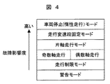
上記のような構成からなるツインクラッチ自動MTにおいて、統合化・グループ化されるフェールセーフモードの一例を図4に示す。故障部位から想定される故障影響度に応じたモードを示している。
(1)車両として回避不可能なシステム欠陥・機能欠落・故障が発生したとき、シフト・クラッチ等の各アクチュエータへの駆動要求を抑制し、車両を停止させる(自力走行を停止し惰性走行のみ)車両停止モード、
(2)アップシフト・ダウンシフトといった変速ギア段の切替を禁止し、現ギア段での走行状態を維持する走行変速段固定モード、
(3)図2の変速機第1入力軸241または、変速機第2入力軸243上に独立して配置されるギア配列のみに限定し、例えば変速機第1入力軸241を奇数軸としたとき、当該軸上に配置される1,3,5速ギア段のみを用いた変速動作を行う片軸走行モード、
(4)検出された故障発生部位では、直接的に変速・発進操作に与える影響度合いは少ないが、正常状態での運転領域・操作を継続すると、故障部位拡大へ起因する可能性があるときなど、変速機に入力されるエンジントルクの上限制限、運転者による変速指令の制限(運転者が変速ギア段を意図的に選択可能なマニュアル変速モードの禁止等)を行う走行制限モード、
(5)運転者への故障発生の報知を異常警告灯,車両状態表示パネルで行う警告モード、
を一例として示す。
FIG. 4 shows an example of the fail-safe mode that is integrated and grouped in the twin clutch automatic MT having the above-described configuration. The mode according to the failure influence degree assumed from the failure part is shown.
(1) When a system defect / function missing / failure that cannot be avoided as a vehicle occurs, the drive request to each actuator such as a shift / clutch is suppressed, and the vehicle is stopped (self-running is stopped and inertial driving only) Vehicle stop mode,
(2) Traveling gear fixed mode that prohibits switching of gears such as upshifts and downshifts and maintains the driving state at the current gears;
(3) It is limited to only the gear arrangement arranged independently on the transmission
(4) Although the degree of influence directly on the shift / start operation is small at the detected failure occurrence site, there is a possibility that the failure region may be expanded if the operation region / operation in the normal state is continued. , An upper limit of engine torque input to the transmission, a travel restriction mode for restricting a shift command by the driver (such as prohibition of a manual shift mode in which the driver can intentionally select a shift gear),
(5) A warning mode in which the driver is informed of the occurrence of a failure with an abnormal warning light, vehicle status display panel,
Is shown as an example.
これは、統合化されたフェールセーフモードは、構成部品・センサ・アクチュエータに応じて、最良のグループ分けがされればよい。 This is because the integrated fail-safe mode may be best grouped according to the components, sensors, and actuators.
一例として、定常走行状態において、図2のシフトアクチュエータ251によって、第1噛合い伝達機構221の位置を移動し、第3ドリブンギア213と係合できない故障が発生したとき、その故障部位はシフトアクチュエータ251の指令異常,第1噛合い伝達機構221の動作不良,第3ドリブンギア213の破損,第2クラッチ209の解放不良による変速機第2入力軸243への負荷トルク等々があげられ、故障部位特定は困難な状況にある。仮に上記第3ドライブギア203と第3ドリブンギア213の組合せが3速ギア段としたとき、3速ギア段のみを使用不可とするフェールセーフモードを実行した場合、本当故障部位は第2クラッチ209であるにも関わらず、3速ギア段以外の変速機第2入力軸上243上のギア段を使用するため、エンスト,急減速、あるいはクラッチ209解放不良によるクラッチ発熱・焼損といった2重故障に至る可能性がある。このように故障部位が限定できない状態において、その周辺・関連部位の故障であっても、フェールセーフ走行が維持できる統合化モードとして、上記の片軸走行モードを選択し、変速機第2入力軸243から変速機出力軸242に回転トルクを伝達する経路を使用しないようにすることで、前記のクラッチ発熱・焼損,及び運転者が危険にさらされる方向の車両挙動を回避することが可能となる。
As an example, when a failure that cannot be engaged with the third driven
図6には、統合化されたフェールセーフモード実行時のタイムチャートの一例を示す。 FIG. 6 shows an example of a time chart when the integrated fail-safe mode is executed.
時間T0にて故障が発生し、予め設定された統合化フェールセーフモードが実行される。時間T2にてイグニッションスイッチ(IGNSW)がOFFとなり、制御ユニットへの電源供給が遮断されたとする。次回イグニッションスイッチがON時には、前回時間T0同様に故障発生(検出)時をトリガとして、フェールセーフモードを実行することになるが、システム的故障影響度合いが大きい場合などは、本例のように前回のフェールセーフモードの実行履歴を制御ユニット内に有する記憶装置等に記憶しておき、時間T3に示す次回イグニッションスイッチON後も前回実行のフェールセーフモードを継続的に実行するように構成することも可能である。 A failure occurs at time T0, and a preset integrated failsafe mode is executed. It is assumed that the ignition switch (IGNSW) is turned off at time T2 and the power supply to the control unit is cut off. When the ignition switch is turned on next time, the fail-safe mode is executed with the time of failure occurrence (detection) as a trigger as in the previous time T0. However, when the degree of system failure influence is large, It is also possible to store the execution history of the fail safe mode in a storage device or the like in the control unit, and continuously execute the fail safe mode of the previous execution even after the next ignition switch is turned on at time T3. .
図8は、本発明に係る自動変速機を備えた自動車の制御装置一実施の形態を示す第2のシステム構成例スケルトン図である。なお、図2と同一符号は、同一部分を示している。 FIG. 8 is a second system configuration example skeleton diagram showing an embodiment of a control apparatus for an automobile equipped with an automatic transmission according to the present invention. The same reference numerals as those in FIG. 2 indicate the same parts.
自動変速機50には、入力軸クラッチ8,アシストクラッチ9,変速機入力軸41,変速機出力軸42,第1ドライブギア1,第2ドライブギア2,第3ドライブギア3,第4ドライブギア4,第5ドライブギア5、および第6ドライブギア6,第1ドリブンギア11,第2ドリブンギア12,第3ドリブンギア13,第4ドリブンギア14,第5ドリブンギア15、および第6ドリブンギア16,第1噛合い伝達機構21,第2噛合い伝達機構22,第3噛合い伝達機構23,回転センサ31,回転センサ32、が設けられている。
The
エンジン7には、入力軸クラッチ入力ディスク8aが連結されており、入力軸クラッチ入力ディスク8aと入力軸クラッチ出力ディスク8bを係合,開放することで、エンジン7のトルクを変速機入力軸41に伝達,遮断することが可能である。入力軸クラッチ8には、一般に乾式単板クラッチが用いられるが、湿式多板クラッチや電磁クラッチなどすべてのクラッチを用いることが可能である。入力軸クラッチ入力ディスク8aと入力軸クラッチ出力ディスク8b間の押付け力(入力軸クラッチトルク)の制御には、電動機(モータ)によって駆動する作動装置(アクチュエータ)2011が用いられており、この押付け力(入力軸クラッチトルク)を調節することで、エンジン7の出力を入力軸41へ伝達、遮断を行うことができるようになっている。
An input shaft clutch input disk 8a is connected to the
入力軸41には、第1ドライブギア1,第2ドライブギア2,第3ドライブギア3,第4ドライブギア4,第5ドライブギア5、および第6ドライブギア6が設けられている。第1ドライブギア1,第2ドライブギア2は変速機入力軸41に固定されており、第3ドライブギア3,第4ドライブギア4,第5ドライブギア5,第6ドライブギア6は、変速機入力軸41に対して回転自在に設けられている。また、変速機入力軸41の回転数である、入力軸回転数を検出する手段として、回転センサ31が設けられている。
The
一方、変速機出力軸42には、第1ドリブンギア11,第2ドリブンギア12,第3ドリブンギア13,第4ドリブンギア14,第5ドリブンギア15、および第6ドリブンギア16が設けられている。第1ドリブンギア11,第2ドリブンギア12は変速機出力軸42に対して回転自在に設けられており、第3ドリブンギア13,第4ドリブンギア14,第5ドリブンギア15,第6ドリブンギア16は変速機出力軸42に固定されている。
On the other hand, the
また、変速機出力軸42の回転数を検出する手段として、回転センサ32が設けられている。
A
第1ドライブギア1と、第1ドリブンギア11とが、第2ドライブギア2と、第2ドリブンギア12とが、第3ドライブギア3と、第3ドリブンギア13とが、第4ドライブギア4と、第4ドリブンギア14とが、第5ドライブギア5と、第5ドリブンギア15とが、第6ドライブギア6と、第6ドリブンギア16とが、それぞれ噛合している。
The first drive gear 1, the first driven gear 11, the
そして、入力軸41には、摩擦伝達機構の一方式であるアシストクラッチ9が備えられており、アシストクラッチ9の伝達トルクを制御することによって、エンジン7のトルクを変速機出力軸42に伝達することが可能である。
The
アシストクラッチ9の伝達トルクの制御には、モータによって駆動するアクチュエータ2014が用いられており、この伝達トルク(アシストクラッチトルク)を調節することで、エンジン7の出力を伝達することができるようになっている。
An
ここで、摩擦伝達機構は、摩擦面の押し付け力によって摩擦力を発生させてトルクを伝達する機構であり、代表的なものとして、乾式単板クラッチ,乾式多板クラッチ,湿式多板クラッチ等がある。本実施例ではアシストクラッチには湿式多版クラッチを用いている。 Here, the friction transmission mechanism is a mechanism that generates a friction force by the pressing force of the friction surface and transmits the torque. Typical examples include a dry single plate clutch, a dry multi-plate clutch, and a wet multi-plate clutch. is there. In this embodiment, a wet multi-plate clutch is used as the assist clutch.
また、第1ドリブンギア11と第2ドリブンギア12の間には、第1ドリブンギア11を変速機出力軸42に係合させたり、第2ドリブンギア12を変速機出力軸42に係合させる第1噛合い伝達機構21が設けられている。したがって、第1ドライブギア1から第1ドリブンギア11へ、または第2ドライブギア2から第2ドリブンギア12へと伝達された回転トルクは、第1噛合い伝達機構21を介して変速機出力軸42に伝達されることになる。
Further, between the first driven gear 11 and the second driven
また、第3ドライブギア3と第4ドライブギア4の間には、第3ドライブギア3を変速機入力軸41に係合させたり、第4ドライブギア4を変速機入力軸41に係合させる、第2噛合い伝達機構22が設けられている。したがって、第3ドライブギア3、または第4ドライブギア4に伝達された回転トルクは、第2噛合い伝達機構22を介して第3ドリブンギア13または第4ドリブンギア14に伝達され、変速機出力軸42に伝達されることになる。
Further, between the
また、第5ドライブギア5には、第5ドライブギア5を変速機入力軸41に係合させる、第3噛合い伝達機構23が設けられている。したがって、第5ドライブギア5に伝達された回転トルクは、第3噛合い伝達機構23を介して第5ドリブンギア15に伝達され、変速機出力軸42に伝達されることになる。
Further, the
ここで、前記噛合い伝達機構21,22,23は、常時噛合い式を用いても良いし、摩擦伝達機構を備え、摩擦面を押しつけることによって回転数を同期させて噛合いを行う同期噛合い式を用いても良い。
Here, the
このように、変速機入力軸41の回転トルクを、変速機出力軸42に伝達するためには、第1噛合い伝達機構21、または第2噛合い伝達機構22、または第3噛合い伝達機構23のうちいずれか一つを変速機入力軸41もしくは変速機出力軸42の軸方向に移動させ、第1ドリブンギア11,第2ドリブンギア12,第3ドライブギア3,第4ドライブギア4,第5ドライブギア5のいずれか一つと係合する必要がある。セレクトアクチュエータ2013によって、シフト/セレクト機構24を動作させ、第1噛合い伝達機構21、または第2噛合い伝達機構22、または第3噛合い伝達機構23のいずれを移動させるかを選択し、シフトアクチュエータ2012によって、シフト/セレクト機構24を動作させることによって、前記第1噛合い伝達機構21、または第2噛合い伝達機構22、または第3噛合い伝達機構23のうち、選択されたいずれか一つの噛合い伝達機構の位置を移動し、第1ドリブンギア11,第2ドリブンギア12,第3ドライブギア3,第4ドライブギア4,第5ドライブギア5のいずれか一つに係合させ、変速機入力軸41の回転トルクを、第1噛合い伝達機構21、または第2噛合い伝達機構22、または第3噛合い伝達機構23のいずれか一つを介して変速機出力軸42へと伝達することができる。
Thus, in order to transmit the rotational torque of the
このように第1ドライブギア1,第2ドライブギア2,第3ドライブギア3,第4ドライブギア4,第5ドライブギア5,第6ドライブギア6から、第1ドリブンギア11,第2ドリブンギア12,第3ドリブンギア13,第4ドリブンギア14,第5ドリブンギア15,第6ドリブンギア6を介して変速機出力軸42に伝達された変速機入力軸41の回転トルクは、変速機出力軸42に連結されたディファレンシャルギア(図示しない)を介して車軸(図示しない)に伝えられる。
Thus, from the first drive gear 1, the
入力軸クラッチ8の伝達トルクを制御する入力軸クラッチアクチュエータ2011,アシストクラッチ9の伝達トルクを制御するアシストクラッチアクチュエータ2014は、モータ制御ユニット104によって、各アクチュエータに設けられたモータ(図示せず)の電流を制御することで各クラッチの伝達トルクの制御を行っている。入力軸クラッチアクチュエータ2011は、モータと、モータの回転運動を直線運動に変換する機構部分から構成され、ウォームギアおよびアームや、ボールネジといった部品で構成される。
The input
また、モータ制御ユニット104によって、セレクトアクチュエータ2013に設けられたモータ(図示せず)の電流を制御することによって、第1噛合い伝達機構21,第2噛合い伝達機構22,第3噛合い伝達機構23のいずれを移動するか選択するためのセレクトレバー(図示しない)のストローク位置である、セレクト位置を移動し、第1噛合い伝達機構21,第2噛合い伝達機構22,第3噛合い伝達機構23のいずれを移動するか選択している。
In addition, the
また、モータ制御ユニット104によって、シフトアクチュエータ2012に設けられたモータ(図示せず)の電流を制御することによって、セレクトアクチュエータ2013によって選択された、第1噛合い伝達機構21,第2噛合い伝達機構22,第3噛合い伝達機構23のいずれかを動作させる荷重またはストローク位置(シフト位置)を制御できるようになっている。
Further, the
セレクトアクチュエータ2013を制御してセレクト位置を制御し、第1噛合い伝達機構21を移動することを選択し、シフトアクチュエータ2012を制御してシフト位置を制御し、第1噛合い伝達機構21と第1ドリブンギア11が噛合して第1速段となる。
The
セレクトアクチュエータ2013を制御してセレクト位置を制御し、第1噛合い伝達機構21を移動することを選択し、シフトアクチュエータ2012を制御してシフト位置を制御し、第1噛合い伝達機構21と第2ドリブンギア12が噛合して第2速段となる。
The
なお、第1噛合い伝達機構21,第2噛合い伝達機構22,第3噛合い伝達機構23を動作させるシフト/セレクト機構24としては、セレクトレバーおよびシフトフォークなどによって構成しても良いし、ドラム式など、噛合い伝達機構21,22,23を移動させるための他の機構を用いても構成可能である。
The shift /
なお、摩擦伝達機構の一方式であるアシストクラッチの連結する前記第6ドライブギアおよび第6ドリブンギアの減速比は、第3ドライブギア3および第3ドリブンギア13によって構成される第3速段の減速比と、第4ドライブギア4および第4ドリブンギア14によって構成される第4速段の減速比との間に設定しても良いし、第4速段と第5速段の間の減速比としても良いし、第3速段相当としても良いし、第4速段相当としても良いし、最高速段相当としても良い。また、例えば第5速段相当として、第5ドライブギア5および第5ドリブンギア15および第3噛合い伝達機構のかわり用いるなど、所定の変速段として設けられた噛合い伝達機構のかわりに摩擦伝達機構を設置することも可能である。さらには複数の摩擦伝達機構を用いて、複数の変速段へ設置することも可能である。
Note that the reduction ratio of the sixth drive gear and the sixth driven gear to which the assist clutch, which is one type of friction transmission mechanism, is connected is the third speed stage constituted by the
このような変速機においても、フェールセーフモードの統合化・グループ化は適用可能であり、上記変速機では、ツインクラッチ自動MTでの片軸走行モードに代わり、アシストクラッチを用いた変速制御を禁止し、従来シングルクラッチ変速動作のみとするシングル変速走行モードなどを備えることができる。 Fail-safe mode integration and grouping can also be applied to such transmissions. In the above transmission, shift control using an assist clutch is prohibited in place of the single-axis travel mode in twin clutch automatic MT. In addition, it is possible to provide a single-shift running mode in which only a conventional single-clutch shift operation is performed.
a1 故障判定手段1
a4 フェールセーフモード選択手段
a5 フェールセーフモードA実行手段
a9 変速機構成アクチュエータ群
100 パワートレーン制御ユニット
101 エンジン制御ユニット
a1 Failure determination means 1
a4 Failsafe mode selection means a5 Failsafe mode A execution means a9 Transmission
Claims (12)
変速機を構成する各センサ・アクチュエータ・デバイス・メカ機構の故障検出時にその故障部位によらず、その故障部位周辺・関連の部位故障から想定される車両への影響度合いに応じて統合化・グループ化したフェールセーフ制御を実行することを特徴とする自動変速機の制御装置。 A plurality of friction transmission mechanisms for transmitting / interrupting driving force between the output shaft of the driving force generation source and the transmission output shaft of the gear type transmission, and a plurality of transmission input shafts respectively connected to the friction transmission mechanism And a control device for an automatic transmission having a plurality of gear trains that selectively connect between the plurality of transmission input shafts and the transmission output shaft by selection of a plurality of synchronous meshing functions,
Integrates / groups according to the degree of impact on the vehicle that is assumed from the failure around the failure part and related parts, regardless of the failure part when detecting a failure of each sensor, actuator, device, or mechanical mechanism that constitutes the transmission A control device for an automatic transmission, characterized in that an integrated fail-safe control is executed.
実行されるフェールセーフ制御は、予め故障部位に応じて選択可能とすることを特徴とする自動変速機の制御装置。 The control apparatus for an automatic transmission according to claim 1,
The automatic transmission control apparatus is characterized in that the fail-safe control to be executed can be selected in advance according to a failure part.
統合化・グループ化されたフェールセーフ制御の数・パターンは、故障部位に応じて備えた故障検出手段よりも少ないことを特徴とする自動変速機の制御装置。 The fail-safe control method and apparatus for an automatic transmission according to claim 1,
An automatic transmission control device characterized in that the number and pattern of integrated and grouped fail-safe controls is smaller than that of failure detection means provided in accordance with a failure part.
統合化・グループ化されたフェールセーフ制御として、少なくとも車両の自力走行を禁止し、車両停止に至るフェールセーフモードを備えることを特徴とする自動変速機の制御装置。 The fail-safe control method and apparatus for an automatic transmission according to claim 1,
A control device for an automatic transmission comprising a fail-safe mode for prohibiting at least self-running of a vehicle and stopping the vehicle as integrated / grouped fail-safe control.
統合化・グループ化されたフェールセーフ制御として、少なくとも現在選択された歯車列での走行を維持するフェールセーフモードを備えることを特徴とする自動変速機の制御装置。 The fail-safe control method and apparatus for an automatic transmission according to claim 1,
A control device for an automatic transmission, comprising: a fail-safe mode that maintains at least the currently selected gear train as integrated / grouped fail-safe control.
変速機を構成する各センサ・アクチュエータ・デバイス・メカ機構の故障検出により統合化・グループ化されたフェールセーフ制御実行を開始したとき、前記故障検出結果の状態に関わらず、前記開始したフェールセーフ制御を継続して実行することを特徴とする自動変速機のフ制御装置。 The fail-safe control method and apparatus for an automatic transmission according to claim 1,
When fail-safe control execution integrated and grouped by detecting the failure of each sensor, actuator, device, and mechanical mechanism constituting the transmission is started, the started fail-safe control is performed regardless of the state of the failure detection result. A control device for an automatic transmission characterized by continuously executing the operation.
変速機を構成する各センサ・アクチュエータ・デバイス・メカ機構の故障検出時にその故障部位によらず、その故障部位周辺・関連の部位故障から想定される車両への影響度合いに応じて統合化・グループ化したフェールセーフ制御を実行することを特徴とする自動変速機の制御方法。 A plurality of friction transmission mechanisms for transmitting / interrupting driving force between the output shaft of the driving force generation source and the transmission output shaft of the gear type transmission, and a plurality of transmission input shafts respectively connected to the friction transmission mechanism And a control method of an automatic transmission having a plurality of gear trains selectively connecting the plurality of transmission input shafts and the transmission output shaft by selecting a plurality of synchronous meshing functions,
Integrates / groups according to the degree of impact on the vehicle that is assumed from the failure around the failure part and related parts, regardless of the failure part when detecting a failure of each sensor, actuator, device, or mechanical mechanism that constitutes the transmission A control method for an automatic transmission, characterized in that an integrated fail-safe control is executed.
実行されるフェールセーフ制御は、予め故障部位に応じて選択可能とすることを特徴とする自動変速機の制御方法。 The fail-safe control method for an automatic transmission according to claim 7,
The control method of the automatic transmission characterized in that the fail-safe control to be executed can be selected in advance according to the failure part.
統合化・グループ化されたフェールセーフ制御の数・パターンは、故障部位に応じて備えた故障検出手段よりも少ないことを特徴とする自動変速機の制御方法。 The fail-safe control method and apparatus for an automatic transmission according to claim 7,
A control method for an automatic transmission characterized in that the number and pattern of integrated and grouped fail-safe controls is smaller than that of failure detection means provided according to a failure part.
統合化・グループ化されたフェールセーフ制御として、少なくとも車両の自力走行を禁止し、車両停止に至るフェールセーフモードを備えることを特徴とする自動変速機の制御方法。 The method of controlling an automatic transmission according to claim 7,
A control method for an automatic transmission, comprising: a fail-safe mode that at least prohibits the vehicle from running on its own and that stops the vehicle as integrated and grouped fail-safe control.
統合化・グループ化されたフェールセーフ制御として、少なくとも現在選択された歯車列での走行を維持するフェールセーフモードを備えることを特徴とする自動変速機の制御方法。 The control apparatus for an automatic transmission according to claim 7,
A method for controlling an automatic transmission comprising a fail-safe mode for maintaining traveling in at least a currently selected gear train as integrated / grouped fail-safe control.
変速機を構成する各センサ・アクチュエータ・デバイス・メカ機構の故障検出により統合化・グループ化されたフェールセーフ制御実行を開始したとき、前記故障検出結果の状態に関わらず、前記開始したフェールセーフ制御を継続して実行することを特徴とする自動変速機のフェールセーフ制御方法及び装置。 The fail-safe control method and apparatus for an automatic transmission according to claim 7,
When fail-safe control execution integrated and grouped by detecting the failure of each sensor, actuator, device, and mechanical mechanism constituting the transmission is started, the started fail-safe control is performed regardless of the state of the failure detection result. A fail-safe control method and apparatus for an automatic transmission characterized by continuously executing
Priority Applications (1)
| Application Number | Priority Date | Filing Date | Title |
|---|---|---|---|
| JP2007204868A JP2009041602A (en) | 2007-08-07 | 2007-08-07 | Control device and control method for automatic transmission |
Applications Claiming Priority (1)
| Application Number | Priority Date | Filing Date | Title |
|---|---|---|---|
| JP2007204868A JP2009041602A (en) | 2007-08-07 | 2007-08-07 | Control device and control method for automatic transmission |
Publications (1)
| Publication Number | Publication Date |
|---|---|
| JP2009041602A true JP2009041602A (en) | 2009-02-26 |
Family
ID=40442563
Family Applications (1)
| Application Number | Title | Priority Date | Filing Date |
|---|---|---|---|
| JP2007204868A Withdrawn JP2009041602A (en) | 2007-08-07 | 2007-08-07 | Control device and control method for automatic transmission |
Country Status (1)
| Country | Link |
|---|---|
| JP (1) | JP2009041602A (en) |
Cited By (3)
| Publication number | Priority date | Publication date | Assignee | Title |
|---|---|---|---|---|
| CN106838296A (en) * | 2017-02-10 | 2017-06-13 | 中国第汽车股份有限公司 | A kind of car automatic mechanical transmission ECU safety monitoring system |
| US10718428B2 (en) | 2015-06-29 | 2020-07-21 | Hitachi Automotive Systems, Ltd. | Controller for vehicle transmission |
| JP2023117098A (en) * | 2022-02-10 | 2023-08-23 | スズキ株式会社 | vehicle controller |
Citations (11)
| Publication number | Priority date | Publication date | Assignee | Title |
|---|---|---|---|---|
| JPH0666367A (en) * | 1992-08-20 | 1994-03-08 | Nissan Motor Co Ltd | Shift device for automatic transmission |
| JPH08145163A (en) * | 1994-11-22 | 1996-06-04 | Toyota Motor Corp | Hydraulic control system for compound clutch type automatic transmission |
| JP2001304401A (en) * | 2000-04-24 | 2001-10-31 | Isuzu Motors Ltd | Vehicle shift control device |
| JP2002525540A (en) * | 1998-09-29 | 2002-08-13 | ゼットエフ、バタビア、リミテッド、ライアビリティ、カンパニー | Method of reducing the thermal load of an automatic vehicle transmission in emergency driving mode |
| JP2003097692A (en) * | 2001-09-27 | 2003-04-03 | Jatco Ltd | Transmission control device for automatic transmission |
| JP2003294134A (en) * | 2002-03-29 | 2003-10-15 | Jatco Ltd | Shift position detection device for automatic transmission |
| JP2005147403A (en) * | 2003-11-17 | 2005-06-09 | Borgwarner Inc | Control method of double clutch transmission |
| JP2006132574A (en) * | 2004-11-02 | 2006-05-25 | Nissan Motor Co Ltd | Twin clutch type manual transmission fail-speed control device |
| JP2006336717A (en) * | 2005-05-31 | 2006-12-14 | Denso Corp | Vehicle control system |
| JP2007010055A (en) * | 2005-06-30 | 2007-01-18 | Denso Corp | Vehicle control system |
| JP2007032702A (en) * | 2005-07-27 | 2007-02-08 | Fuji Heavy Ind Ltd | Hydraulic control device for automatic transmission |
-
2007
- 2007-08-07 JP JP2007204868A patent/JP2009041602A/en not_active Withdrawn
Patent Citations (11)
| Publication number | Priority date | Publication date | Assignee | Title |
|---|---|---|---|---|
| JPH0666367A (en) * | 1992-08-20 | 1994-03-08 | Nissan Motor Co Ltd | Shift device for automatic transmission |
| JPH08145163A (en) * | 1994-11-22 | 1996-06-04 | Toyota Motor Corp | Hydraulic control system for compound clutch type automatic transmission |
| JP2002525540A (en) * | 1998-09-29 | 2002-08-13 | ゼットエフ、バタビア、リミテッド、ライアビリティ、カンパニー | Method of reducing the thermal load of an automatic vehicle transmission in emergency driving mode |
| JP2001304401A (en) * | 2000-04-24 | 2001-10-31 | Isuzu Motors Ltd | Vehicle shift control device |
| JP2003097692A (en) * | 2001-09-27 | 2003-04-03 | Jatco Ltd | Transmission control device for automatic transmission |
| JP2003294134A (en) * | 2002-03-29 | 2003-10-15 | Jatco Ltd | Shift position detection device for automatic transmission |
| JP2005147403A (en) * | 2003-11-17 | 2005-06-09 | Borgwarner Inc | Control method of double clutch transmission |
| JP2006132574A (en) * | 2004-11-02 | 2006-05-25 | Nissan Motor Co Ltd | Twin clutch type manual transmission fail-speed control device |
| JP2006336717A (en) * | 2005-05-31 | 2006-12-14 | Denso Corp | Vehicle control system |
| JP2007010055A (en) * | 2005-06-30 | 2007-01-18 | Denso Corp | Vehicle control system |
| JP2007032702A (en) * | 2005-07-27 | 2007-02-08 | Fuji Heavy Ind Ltd | Hydraulic control device for automatic transmission |
Cited By (3)
| Publication number | Priority date | Publication date | Assignee | Title |
|---|---|---|---|---|
| US10718428B2 (en) | 2015-06-29 | 2020-07-21 | Hitachi Automotive Systems, Ltd. | Controller for vehicle transmission |
| CN106838296A (en) * | 2017-02-10 | 2017-06-13 | 中国第汽车股份有限公司 | A kind of car automatic mechanical transmission ECU safety monitoring system |
| JP2023117098A (en) * | 2022-02-10 | 2023-08-23 | スズキ株式会社 | vehicle controller |
Similar Documents
| Publication | Publication Date | Title |
|---|---|---|
| US7735388B2 (en) | Control system and method for automatic transmission | |
| CN102089197B (en) | vehicle controls | |
| CN101036008B (en) | Method for optimizing gear shifts and corresponding control device | |
| JP5847521B2 (en) | Dual clutch automatic transmission | |
| JP2004116683A (en) | Output shaft lock device for multiple clutch transmission | |
| EP2481948B1 (en) | Shift device for vehicle | |
| EP2481956A1 (en) | Shift device for vehicle | |
| WO2009139250A1 (en) | Abnormality judgment device and abnormality judgment method of shift switching mechanism | |
| JP5056635B2 (en) | Automatic transmission control device for abnormalities in automatic manual transmission | |
| CN103939221B (en) | Control device for the vehicle equipped with manual transmission | |
| CN100554715C (en) | Clutch control device | |
| CN101144536A (en) | Control device and control method for vehicle | |
| JP2009041602A (en) | Control device and control method for automatic transmission | |
| JP5835573B2 (en) | Automatic transmission clutch control device | |
| US6698302B2 (en) | Method of keeping track of the operating position of an actuator in an automated gear-shift transmission | |
| JP2006283816A (en) | Clutch controller | |
| JP2005530111A (en) | Detection method of erroneous neutral in automatic transmission system | |
| JP2008075814A (en) | Clutch device | |
| JP4742928B2 (en) | Shift control device for multiple clutch transmission | |
| JP4696880B2 (en) | Control device for clutch type transmission | |
| JP5039611B2 (en) | Overspeed prevention control method and apparatus for automatic transmission | |
| JP4939976B2 (en) | Control device and control method for vehicle with automatic clutch | |
| JP2008128438A (en) | Shift control device for transmission | |
| JP2005282741A (en) | Control device for hybrid vehicle | |
| JP4868760B2 (en) | Clutch control device |
Legal Events
| Date | Code | Title | Description |
|---|---|---|---|
| A621 | Written request for application examination |
Effective date: 20090611 Free format text: JAPANESE INTERMEDIATE CODE: A621 |
|
| A711 | Notification of change in applicant |
Free format text: JAPANESE INTERMEDIATE CODE: A712 Effective date: 20091224 |
|
| A977 | Report on retrieval |
Free format text: JAPANESE INTERMEDIATE CODE: A971007 Effective date: 20110811 |
|
| A131 | Notification of reasons for refusal |
Free format text: JAPANESE INTERMEDIATE CODE: A131 Effective date: 20110816 |
|
| A761 | Written withdrawal of application |
Free format text: JAPANESE INTERMEDIATE CODE: A761 Effective date: 20111019 |