JP2009041663A - Top plate connecting member and connecting structure - Google Patents
Top plate connecting member and connecting structure Download PDFInfo
- Publication number
- JP2009041663A JP2009041663A JP2007207132A JP2007207132A JP2009041663A JP 2009041663 A JP2009041663 A JP 2009041663A JP 2007207132 A JP2007207132 A JP 2007207132A JP 2007207132 A JP2007207132 A JP 2007207132A JP 2009041663 A JP2009041663 A JP 2009041663A
- Authority
- JP
- Japan
- Prior art keywords
- top plate
- storage unit
- plate
- connecting member
- fixed
- Prior art date
- Legal status (The legal status is an assumption and is not a legal conclusion. Google has not performed a legal analysis and makes no representation as to the accuracy of the status listed.)
- Granted
Links
- 239000002023 wood Substances 0.000 claims abstract description 19
- 230000002093 peripheral effect Effects 0.000 claims 1
- 238000010276 construction Methods 0.000 abstract description 4
- 238000005192 partition Methods 0.000 description 11
- 239000000463 material Substances 0.000 description 6
- 239000002184 metal Substances 0.000 description 6
- 238000000034 method Methods 0.000 description 4
- 229910000831 Steel Inorganic materials 0.000 description 1
- 229920002522 Wood fibre Polymers 0.000 description 1
- 238000005516 engineering process Methods 0.000 description 1
- 239000007769 metal material Substances 0.000 description 1
- 239000002245 particle Substances 0.000 description 1
- 239000011120 plywood Substances 0.000 description 1
- 239000011090 solid board Substances 0.000 description 1
- 239000010959 steel Substances 0.000 description 1
- 239000002025 wood fiber Substances 0.000 description 1
Images


Landscapes
- Connection Of Plates (AREA)
- Furniture Connections (AREA)
- Combinations Of Kitchen Furniture (AREA)
Abstract
Description
本発明は、クローゼット収納ユニットなどにおける天板の連結部材および連結構造に関する。 The present invention relates to a top plate connecting member and a connecting structure in a closet storage unit or the like.
クローゼットなどの収納空間において、たとえば該収納空間の奥壁に沿って設置する第一の収納ユニットと該収納空間の側壁に沿って設置する第二の収納ユニットとを一体的に組み付けてクローゼット収納ユニットとする場合がある。このような場合においては、第一の収納ユニットの天板と第二の収納ユニットの天板とを面一にしつつ直角に突き合わせて連結する必要がある。 In a storage space such as a closet, for example, a first storage unit installed along the back wall of the storage space and a second storage unit installed along the side wall of the storage space are integrally assembled to form a closet storage unit. It may be. In such a case, the top plate of the first storage unit and the top plate of the second storage unit need to be abutted at right angles while being flush with each other.
このような天板同士の連結に際して、下記特許文献1記載技術を適用することができる。この技術は、一方の棚の側部木口面に他方の棚の端部木口面を連結するに際して、断面L字形の取付金具を用い、その一方の接続片を一方の棚の側部木口面に当て、他方の接続片を他方の棚の端部木口面に当てて、各々を木ねじなどで固定するものである。
コーナー部における棚同士の連結構造に関する特許文献1記載の技術を天板同士の連結に適用することは可能であるが、この従来技術によると、2つの棚部材同士の位置合わせが容易ではない。また、棚部材の加工精度や他部材との取り合いなどの関係から、棚部材同士を取付金具で連結固定したときに、一方の棚の側部木口と他方の棚の端部木口との間に隙間が生ずることがあり、外観上見苦しいものとなっていた。 Although it is possible to apply the technique of patent document 1 regarding the connection structure of the shelves in a corner part to the connection of top boards, according to this prior art, position alignment of two shelf members is not easy. In addition, due to the processing accuracy of the shelf members and the relationship with other members, when the shelf members are connected and fixed with mounting brackets, between the side end of one shelf and the end end of the other shelf There was a case where a gap was formed, and the appearance was unsightly.
したがって、本発明が解決しようとする課題は、天板同士の連結において位置決めが簡便に行えるようにするとともに、連結部において隙間が生じても外観上見えなくして施工の自由度を大きくすることにある。 Therefore, the problem to be solved by the present invention is to enable easy positioning in the connection between the top plates, and to increase the degree of freedom of construction by making the appearance invisible even if a gap occurs in the connection part. is there.
上記の課題を達成するため、請求項1に係る本発明は、2枚の天板同士を少なくとも下面が略同一になるようにして一方の天板の長手側木口と他方の天板の短手側木口とを突き合わせて連結固定するために用いる天板の連結部材であって、一方の対向する辺を第一辺および第二辺とし、他方の対向する辺を第三辺および第四辺として、これらからなる四周辺を有する平面視略矩形状の板本体を有し、その第一辺および第二辺に沿って各々木ねじなどの固定具を挿通させる複数の孔が板本体を貫通して形成され、第二辺と第三辺とがなす角部に平面視略矩形状の切欠きが設けられ、第四辺の第一辺側に板本体の表面から垂立する垂直片が設けられ、且つ、前記切欠きの第二辺に平行な端面から第二辺までの距離と、前記垂直片の第二辺側の端面から第二辺までの距離とが略同一とされていることを特徴とする。 In order to achieve the above object, the present invention according to claim 1 is directed so that at least the bottom surfaces of two top plates are substantially the same, and the long side end of one top plate and the short side of the other top plate. It is a connecting member of the top plate used for abutting and fixing the side end, and one opposing side is the first side and the second side, and the other opposing side is the third side and the fourth side And a plate body having a substantially rectangular shape in plan view having four peripheries of these, and a plurality of holes through which a fixing tool such as a wood screw is inserted through the plate body along the first side and the second side. Formed, a notch having a substantially rectangular shape in plan view is provided at a corner formed by the second side and the third side, and a vertical piece extending from the surface of the plate body is provided on the first side of the fourth side. And the distance from the end surface parallel to the second side of the notch to the second side, and the end surface on the second side of the vertical piece Wherein the distance La to the second side are substantially the same.
請求項2に係る本発明は、第一の収納ユニットの天板の短手側木口と第二の収納ユニットの天板の長手側木口とを突き合わせた状態で請求項1記載の連結部材を用いて連結固定してなる連結構造であって、連結部材の切欠きの第二辺に平行な端面が第二の収納ユニットの天板の端部に固定された縦板の長手側木口に当接されるとともに、連結部材の垂直片の第二辺側の端面が第二の収納ユニットの天板の長手側木口に当接された状態で、第一の収納ユニットの天板の短手側木口と第二の収納ユニットの天板の長手側木口とが突き合わされており、この突き合わせ状態で連結部材の第一辺および第二辺に沿った孔を挿通する木ねじなどの固定具により第一および第二の収納ユニットの天板同士が連結固定されていることを特徴とする。 The present invention according to claim 2 uses the connecting member according to claim 1 in a state where the short side end of the top plate of the first storage unit and the long side end of the top plate of the second storage unit are abutted. The connection structure is formed by connecting and fixing, and the end surface parallel to the second side of the notch of the connection member abuts the longitudinal side end of the vertical plate fixed to the end of the top plate of the second storage unit. In addition, the short side end of the top plate of the first storage unit in a state in which the end surface of the second side of the vertical piece of the connecting member is in contact with the long side end of the top plate of the second storage unit And the longitudinal side lip of the top plate of the second storage unit are in abutment, and in this abutment state, the first and second fasteners such as wood screws are inserted through the holes along the first side and the second side of the connecting member. The top plates of the second storage unit are connected and fixed together.
本発明によれば、一方の天板の短手側木口と他方の天板の長手側木口とを突き合わせた状態で連結するときに、連結部材の切欠きの第二辺に平行な端面を第二の収納ユニットの天板の端部に固定された縦板の長手側木口に当接させるとともに、連結部材の垂直片の第二辺側の端面を第二の収納ユニットの天板の長手側木口に当接させることで、連結部材を第二の収納ユニットの天板に対して容易に位置決めすることができ、この位置を保持しつつ連結部材を第二の収納ユニットに対して木ねじなどの固定具で固定することができる。 According to the present invention, when the short side end of one top plate and the long side end of the other top plate are connected to each other, the end surface parallel to the second side of the notch of the connecting member is The vertical side of the vertical plate of the second storage unit is brought into contact with the longitudinal side end of the vertical plate fixed to the end of the top plate of the second storage unit, and the end surface on the second side of the vertical piece of the connecting member is set to the long side of the top plate of the second storage unit The contact member can be easily positioned with respect to the top plate of the second storage unit by abutting against the wooden mouth, and the connection member can be positioned with respect to the second storage unit, such as a wood screw, while maintaining this position. Can be fixed with a fixture.
次いで、このようにして固定された第二の収納ユニットの天板の長手側木口に対して第一の収納ユニットの天板の短手側木口を突き合わせた状態にして、第一の収納ユニットの天板を連結部材に対して固定するが、この際、連結部材の垂直片に第一の収納ユニットの天板の長手側木口を当接させることで容易に位置決めすることができる。 Next, the short side end of the top plate of the first storage unit is abutted against the long side end of the top plate of the second storage unit fixed in this manner, and the first storage unit The top plate is fixed with respect to the connecting member. At this time, the top plate of the first storage unit can be positioned easily by bringing the top end of the top plate into contact with the vertical piece of the connecting member.
しかも、このようにして得られた連結構造において、天板の加工精度や天板同士の取り合いなどの関係から一方の収納ユニットの天板の短手側木口と他方の収納ユニットの天板の長手側木口との間に多少の隙間が発生しても、連結部材の垂直片がこの隙間を隠すので、隙間による外観上の見苦しさを露呈することがない。したがって、天板同士の連結における施工の自由度が大きくなる。 Moreover, in the connection structure obtained in this way, the top side of the top plate of one storage unit and the length of the top plate of the other storage unit due to the processing accuracy of the top plate and the relationship between the top plates, etc. Even if a slight gap is generated between the side end and the side piece, the vertical piece of the connecting member hides the gap, so that the appearance is not unsightly due to the gap. Therefore, the freedom of construction in connecting the top plates increases.
本発明の天板の連結部材ないし連結構造は、クローゼットの内部に設けられる収納ユニットや部屋に設けられる収納ユニットを互いに直交状またはL字形に接続する際に天板同士を連結する連結部材ないし連結構造である。 The connecting member or connecting structure of the top plates of the present invention is a connecting member or connecting member for connecting the top plates to each other when connecting the storage units provided in the closet or the storage units provided in the room in an orthogonal or L-shape. Structure.
収納ユニットは天板のほか縦板(側板、中仕切板など)などで形成されるが、これら天板、縦板などは木質系板材、金属加工板材などで形成され、特に木質系板材が適している。天板、縦板などを木質系板材で形成する場合は、無垢板、合板、集成板、木質繊維板(MDFなど)、パーティクルボード、単板積層板(LVL)などを利用する。 The storage unit is formed of vertical plates (side plates, partition plates, etc.) in addition to the top plate. These top plates, vertical plates, etc. are formed of wood-based plate materials, metal processed plate materials, etc., especially wood-based plate materials are suitable. ing. When forming a top board, a vertical board, etc. with a wood-type board material, a solid board, a plywood board, a laminated board, a wood fiber board (MDF etc.), a particle board, a single board laminated board (LVL), etc. are utilized.
連結部材の材質は、強度のある材料であれば限定されないが、鋼などの金属材が好ましい。連結部材におけるL字形の切欠きの挟角は90度が好ましく、垂直片の形状は矩形状が好ましい。 Although the material of a connection member will not be limited if it is a strong material, Metal materials, such as steel, are preferable. The included angle of the L-shaped notch in the connecting member is preferably 90 degrees, and the shape of the vertical piece is preferably rectangular.
連結部材の切欠きにおける第二辺に平行な端面から第二辺までの距離(D1)と、垂直片の第二辺側の端面から第二辺までの距離(D2)とは略同一寸法とされるが、これらD1,D2は板本体の幅W0の1/2程度とすることが好ましい。したがって、垂直片の幅W1も板本体の幅W0の1/2程度である。 The distance (D 1 ) from the end surface parallel to the second side to the second side in the notch of the connecting member is substantially the same as the distance (D 2 ) from the end surface on the second side of the vertical piece to the second side. The dimensions D 1 and D 2 are preferably about ½ of the width W 0 of the plate body. Therefore, the width W 1 of the vertical piece is also about ½ of the width W 0 of the plate body.
切欠きの長さLは第二の収納ユニットの縦板の厚さ寸法に等しいかそれ以下とする。垂直片の高さHは第一の収納ユニットの天板の厚さ寸法に略等しいかそれ以下とする。 The length L of the notch is equal to or less than the thickness dimension of the vertical plate of the second storage unit. The height H of the vertical piece is approximately equal to or less than the thickness dimension of the top plate of the first storage unit.
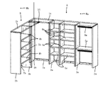
図4はクローゼット内部の壁Wの内隅にメイン収納ユニットAとサブ収納ユニットBとをL字形に配置して連結したクローゼット収納構造を示す。 FIG. 4 shows a closet storage structure in which a main storage unit A and a sub storage unit B are arranged in an L shape and connected to an inner corner of a wall W inside the closet.
図4に示すように、メイン収納ユニットAは、天板1a、側板2a、中仕切板3a、さらに、可動棚4a、固定棚5a、ハンガーパイプ6aなどを有する。メイン収納ユニットAは、奥壁Waに対して内隅側の側板2aおよび幅木7aが木ねじ(図示せず)で直接固定され、右側の側板2aが床に対してL形金具(図示せず)で固定される。
As shown in FIG. 4, the main storage unit A includes a top plate 1a, a
サブ収納ユニットBも略同様の構成であり、天板1b、側板2b、中仕切板3b、さらに、可動棚4b、固定棚5bなどを有する。サブ収納ユニットBは、側壁Wbに対して幅木7bが木ねじ(図示せず)で直接固定され、側板2bが床に対してL形金具(図示せず)で固定される。サブ収納ユニットBは一枚の側板2bのみを有する。
The sub storage unit B has substantially the same configuration, and includes a
メイン収納ユニットAの天板1aは奥壁Waに対してL形金具(図示せず)で固定される。また、天板1aと左右側板2a、天板1aと中仕切板3aとは、L形金具または着脱自在のワンタッチ継手など(図示せず)を介して固定される。
The top plate 1a of the main storage unit A is fixed to the back wall Wa with an L-shaped bracket (not shown). The top plate 1a and the left and
同様に、サブ収納ユニットBの天板1bは側壁Wbに対してL形金具(図示せず)で固定される。また、天板1bと側板2b、天板1bと中仕切板3bとは、L形金具または着脱自在のワンタッチ継手など(図示せず)を介して固定される。
Similarly, the
メイン収納ユニットAおよびサブ収納ユニットBにおいて、可動棚4a,4bは側板2a,2bと中仕切板3a,3b、または中仕切板3a,3b同士の間で、側板2a,2bや中仕切板3a,3bのダボ穴(符号なし)に挿入したダボなど(図示せず)を介して容易に取り外し可能に架設される棚であり、固定棚5a,5bは木ねじなどの固定具(図示せず)を外さない限り外れないように架設される棚である。ハンガーパイプ6aは、メイン収納ユニットAにおいて、その両端が側板2aおよび中仕切板3aのダボ穴(符号なし)に嵌入固定されたブラケット(図示せず)に載置固定される。なお、メイン収納ユニットAにおいては、側壁Wbに固定した側板2aと中仕切板3aとの間の収納空間にもハンガーパイプ6aが設けられるが、図4では図示省略されている(図1に図示)。
In the main storage unit A and the sub storage unit B, the
図4に示すクローゼット収納構造において、メイン収納ユニットAの天板1aとサブ収納ユニットBの天板1bとが本発明の実施形態による天板連結部材によって連結されており、本発明の実施形態による天板連結構造が採用されている。
In the closet storage structure shown in FIG. 4, the top plate 1a of the main storage unit A and the
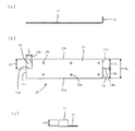
まず、天板連結部材について図3を参照して説明すると、本発明実施形態による天板連結部材が連結金具10として示されている。 First, a top plate connecting member will be described with reference to FIG. 3. A top plate connecting member according to an embodiment of the present invention is shown as a connecting fitting 10.
この連結金具10は平面視略矩形状の板本体11を有する。ここで、板本体11の一方の対向する辺を第一辺11aおよび第二辺11bとし、他方の対向する辺を第三辺11cおよび第四辺11dとすれば、第一辺11aおよび第二辺11bに沿って、各々、木ねじなどの固定具(図示せず)を挿通させるための複数の孔12a,12bが形成されている。板本体11の第三辺11cおよび第四辺11dの長さをW0とする。
The connecting fitting 10 has a
板本体11の第二辺11bと第三辺11cとがなす角には平面視略矩形状の切欠き13が形成されている。切欠き13の第二辺11bに平行な端面13aから第二辺11bまでの距離をD1とし、該端面13aの第二辺11bに沿った長さをLとする。
A
また、板本体11の第四辺11dの第一辺11a側には、板本体11の表面から垂直に折り曲げられた矩形状の垂直片14が設けられている。垂直片14の第二辺11b側の端面14aは垂直に延びている。垂直片14の第二辺側端面14aから第二辺11bまでの距離をD2とすると、D1=D2である。また、垂直片14の第四辺11dに沿った長さ(幅)をW1とし、垂直方向の高さをHとする。この実施形態では、W1とD2がいずれも板本体11の幅W0の略1/2とされている。
A rectangular
この連結金具10を用いてメイン収納ユニットAの天板1aとサブ収納ユニットBの天板1bとを連結した天板連結構造が図1および図2に示されている。連結金具10の切欠き13の第二辺11bに沿った長さLはメイン収納ユニットAの側板2aの厚さ寸法と略同一であり、垂直片14の高さHはサブ収納ユニットBの天板1bの厚さ寸法と略同一である。
A top plate connection structure in which the top plate 1a of the main storage unit A and the
連結金具10によるメイン収納ユニットAの天板1aとサブ収納ユニットBの天板1bとの連結方法を説明する。
A method of connecting the top plate 1a of the main storage unit A and the
(a)まず、図1および図2に示すように、連結金具10の切欠き13の第二辺11bに平行な端面13aを側板2aの長手側木口2aLに当接させ、且つ、垂直片14の第二辺端面14aをメイン収納ユニットAの天板1aの長手側木口1aLに当接させる。さらに、切欠き13の第三辺11cに平行な端面13bを側板2aの内面に押し付ける。
(A) First, as shown in FIGS. 1 and 2, the end face 13 a parallel to the
(b)この位置関係を保持しつつ、連結金具10の第二辺11bに沿った木ねじ用孔12bに挿入した木ねじ7aによって連結金具10とメイン収納ユニットAの天板1aとを固定する。
(B) While maintaining this positional relationship, the connection fitting 10 and the top plate 1a of the main storage unit A are fixed by the wood screws 7a inserted into the wood screw holes 12b along the
(c)これによって連結金具10がメイン収納ユニットAの天板1aに対して所定の位置関係に固定されて不動の状態となるので、この連結金具10に対して、サブ収納ユニットBの天板1bの短手側木口1bSをメイン収納ユニットAの天板1aの長手側木口1aLに当接させた状態にして、連結金具10の第一辺11aに沿った木ねじ用孔12aに挿入した木ねじ7bによってサブ収納ユニットBの天板1bを固定する。
(C) As a result, the connecting
以上に説明した連結方法によれば、メイン収納ユニットAの天板1aおよびサブ収納ユニットBの天板1bに対して連結金具10の位置決めを簡単に行うことができる。さらに、天板1a,1b同士の間に隙間が発生しても、連結金具10の垂直片14によりその隙間が隠蔽されるので、施工の自由度が大きくなる。
According to the connection method described above, the connection fitting 10 can be easily positioned with respect to the top plate 1a of the main storage unit A and the
A メイン収納ユニット(第二の収納ユニット)
B サブ収納ユニット(第一の収納ユニット)
1a,1b 天板
1aL,1bL 天板の長手側木口
1bS 天板の短手側木口
2a,2b 側板
2aL 側板の長手側木口
3a,3b 中仕切板
10 連結金具(天板の連結部材)
11 板本体
11a 板本体の第一辺
11b 板本体の第二辺
11c 板本体の第三辺
11d 板本体の第四辺
12a,12b 木ねじ用孔
13 切欠き
13a 切欠きの第二辺に平行な端面
13b 切欠きの第三辺に平行な端面
14 垂直片
14a 垂直片の第二辺側の端面
14b 垂直片の内側面
W0 板本体の幅
W1 垂直片の幅
H 垂直片の高さ
D1 切欠きの幅
D2 垂直片がない部分の幅(=D1)
L 切欠きの長さ
A Main storage unit (second storage unit)
B Sub storage unit (first storage unit)
DESCRIPTION OF
11 plate main body 11a
L Notch length
Claims (2)
Priority Applications (1)
| Application Number | Priority Date | Filing Date | Title |
|---|---|---|---|
| JP2007207132A JP4891862B2 (en) | 2007-08-08 | 2007-08-08 | Top plate connection member and connection structure |
Applications Claiming Priority (1)
| Application Number | Priority Date | Filing Date | Title |
|---|---|---|---|
| JP2007207132A JP4891862B2 (en) | 2007-08-08 | 2007-08-08 | Top plate connection member and connection structure |
Publications (3)
| Publication Number | Publication Date |
|---|---|
| JP2009041663A true JP2009041663A (en) | 2009-02-26 |
| JP2009041663A5 JP2009041663A5 (en) | 2010-09-09 |
| JP4891862B2 JP4891862B2 (en) | 2012-03-07 |
Family
ID=40442610
Family Applications (1)
| Application Number | Title | Priority Date | Filing Date |
|---|---|---|---|
| JP2007207132A Active JP4891862B2 (en) | 2007-08-08 | 2007-08-08 | Top plate connection member and connection structure |
Country Status (1)
| Country | Link |
|---|---|
| JP (1) | JP4891862B2 (en) |
Cited By (1)
| Publication number | Priority date | Publication date | Assignee | Title |
|---|---|---|---|---|
| KR101936017B1 (en) | 2018-06-18 | 2019-01-07 | 주식회사 엘론산업 | Assembly for furniture |
Citations (6)
| Publication number | Priority date | Publication date | Assignee | Title |
|---|---|---|---|---|
| JPS425476Y1 (en) * | 1964-12-15 | 1967-03-18 | ||
| JPS4884406A (en) * | 1972-02-12 | 1973-11-09 | ||
| JPS57122809A (en) * | 1981-01-21 | 1982-07-30 | Arupusu Sttel Kk | Eathquake resistance metal fitting for stacked furmture |
| JPS6313908A (en) * | 1986-07-02 | 1988-01-21 | ドラ−フタイト工業株式会社 | Method of connecting wood |
| JPH07213360A (en) * | 1994-02-04 | 1995-08-15 | Ibiden Co Ltd | Connecting structure for rack using corner part |
| JPH0814224A (en) * | 1994-06-27 | 1996-01-16 | Kooyoo Sanko:Kk | Three-axis clamp device for square frame member |
-
2007
- 2007-08-08 JP JP2007207132A patent/JP4891862B2/en active Active
Patent Citations (6)
| Publication number | Priority date | Publication date | Assignee | Title |
|---|---|---|---|---|
| JPS425476Y1 (en) * | 1964-12-15 | 1967-03-18 | ||
| JPS4884406A (en) * | 1972-02-12 | 1973-11-09 | ||
| JPS57122809A (en) * | 1981-01-21 | 1982-07-30 | Arupusu Sttel Kk | Eathquake resistance metal fitting for stacked furmture |
| JPS6313908A (en) * | 1986-07-02 | 1988-01-21 | ドラ−フタイト工業株式会社 | Method of connecting wood |
| JPH07213360A (en) * | 1994-02-04 | 1995-08-15 | Ibiden Co Ltd | Connecting structure for rack using corner part |
| JPH0814224A (en) * | 1994-06-27 | 1996-01-16 | Kooyoo Sanko:Kk | Three-axis clamp device for square frame member |
Cited By (1)
| Publication number | Priority date | Publication date | Assignee | Title |
|---|---|---|---|---|
| KR101936017B1 (en) | 2018-06-18 | 2019-01-07 | 주식회사 엘론산업 | Assembly for furniture |
Also Published As
| Publication number | Publication date |
|---|---|
| JP4891862B2 (en) | 2012-03-07 |
Similar Documents
| Publication | Publication Date | Title |
|---|---|---|
| JP6762939B2 (en) | Panels with mechanical locking devices and assembled products with those panels | |
| JP2021521394A (en) | Symmetric tongue and T-cross | |
| JP2023505131A (en) | Mechanical locking system for panels | |
| JPH10246212A (en) | Fixture using metal and wood board | |
| US20170340107A1 (en) | Single dovetail tenon joint mechanism | |
| US20100034582A1 (en) | Interlocking connector system | |
| JP2002161632A (en) | Floor laying structure | |
| JP4891862B2 (en) | Top plate connection member and connection structure | |
| JP5086694B2 (en) | Vertical skirting boards for stairs, skirting boards for stairs and stairs | |
| CA2378063A1 (en) | No slip corner joint | |
| US20100253195A1 (en) | Plywood cabinet | |
| JP7117523B2 (en) | wall underlayment | |
| JP5793687B2 (en) | Sleeve wall structure | |
| US20140292169A1 (en) | Built-in closet assembly | |
| JP2008031737A (en) | Connecting structure of wall panel and ceiling backing material | |
| JP2011236577A (en) | Stairs, side plate for forming stairs, and stairs construction method | |
| JP2008180041A (en) | Wall panel | |
| JP2010038298A (en) | Connecting implement for top plate and method for connecting top plate using the same | |
| JPH11141023A (en) | Joint structure between wall panel and floor panel and building unit | |
| JP2017082577A (en) | Interior wall device, interior wall structure and interior wall construction method | |
| CN110094028B (en) | Indoor assembled quick-assembly combined decorative plate and construction method thereof | |
| JP2018150735A (en) | Installation assisting tool for outset folding door | |
| JP2023076359A (en) | Mounting member and mounting structure for wall hanging article | |
| JP2007291702A (en) | Facing panel mounting structure | |
| JP2025130601A (en) | Corner materials and wall structures |
Legal Events
| Date | Code | Title | Description |
|---|---|---|---|
| A521 | Written amendment |
Free format text: JAPANESE INTERMEDIATE CODE: A523 Effective date: 20100728 |
|
| A621 | Written request for application examination |
Free format text: JAPANESE INTERMEDIATE CODE: A621 Effective date: 20100728 |
|
| A521 | Written amendment |
Free format text: JAPANESE INTERMEDIATE CODE: A523 Effective date: 20110706 |
|
| A977 | Report on retrieval |
Free format text: JAPANESE INTERMEDIATE CODE: A971007 Effective date: 20111027 |
|
| TRDD | Decision of grant or rejection written | ||
| A01 | Written decision to grant a patent or to grant a registration (utility model) |
Free format text: JAPANESE INTERMEDIATE CODE: A01 Effective date: 20111129 |
|
| A01 | Written decision to grant a patent or to grant a registration (utility model) |
Free format text: JAPANESE INTERMEDIATE CODE: A01 |
|
| A61 | First payment of annual fees (during grant procedure) |
Free format text: JAPANESE INTERMEDIATE CODE: A61 Effective date: 20111216 |
|
| R150 | Certificate of patent or registration of utility model |
Ref document number: 4891862 Country of ref document: JP Free format text: JAPANESE INTERMEDIATE CODE: R150 Free format text: JAPANESE INTERMEDIATE CODE: R150 |
|
| FPAY | Renewal fee payment (event date is renewal date of database) |
Free format text: PAYMENT UNTIL: 20141222 Year of fee payment: 3 |