JP2009041902A - Lock and striker raising assembly with swivel and rotary lockhead, especially for inertial working weapons using recoil kinetic energy - Google Patents
Lock and striker raising assembly with swivel and rotary lockhead, especially for inertial working weapons using recoil kinetic energy Download PDFInfo
- Publication number
- JP2009041902A JP2009041902A JP2008187632A JP2008187632A JP2009041902A JP 2009041902 A JP2009041902 A JP 2009041902A JP 2008187632 A JP2008187632 A JP 2008187632A JP 2008187632 A JP2008187632 A JP 2008187632A JP 2009041902 A JP2009041902 A JP 2009041902A
- Authority
- JP
- Japan
- Prior art keywords
- swivel
- weapon
- assembly
- lock
- spring
- Prior art date
- Legal status (The legal status is an assumption and is not a legal conclusion. Google has not performed a legal analysis and makes no representation as to the accuracy of the status listed.)
- Granted
Links
- 238000007599 discharging Methods 0.000 claims abstract description 7
- 238000011084 recovery Methods 0.000 claims description 32
- 238000010304 firing Methods 0.000 claims description 17
- XEEYBQQBJWHFJM-UHFFFAOYSA-N Iron Chemical compound [Fe] XEEYBQQBJWHFJM-UHFFFAOYSA-N 0.000 claims description 10
- 239000003814 drug Substances 0.000 claims description 7
- 238000003780 insertion Methods 0.000 claims description 5
- 230000037431 insertion Effects 0.000 claims description 5
- 229910052742 iron Inorganic materials 0.000 claims description 5
- 230000035939 shock Effects 0.000 claims 1
- 239000012141 concentrate Substances 0.000 abstract description 3
- 230000008878 coupling Effects 0.000 description 7
- 238000010168 coupling process Methods 0.000 description 7
- 238000005859 coupling reaction Methods 0.000 description 7
- 230000008901 benefit Effects 0.000 description 5
- 230000009471 action Effects 0.000 description 2
- 238000006243 chemical reaction Methods 0.000 description 2
- 230000006835 compression Effects 0.000 description 2
- 238000007906 compression Methods 0.000 description 2
- 208000007271 Substance Withdrawal Syndrome Diseases 0.000 description 1
- 230000007246 mechanism Effects 0.000 description 1
- 238000000034 method Methods 0.000 description 1
- 230000008569 process Effects 0.000 description 1
- 238000000926 separation method Methods 0.000 description 1
- 229910000679 solder Inorganic materials 0.000 description 1
- 230000007704 transition Effects 0.000 description 1
- 230000003313 weakening effect Effects 0.000 description 1
Images





Classifications
-
- F—MECHANICAL ENGINEERING; LIGHTING; HEATING; WEAPONS; BLASTING
- F41—WEAPONS
- F41A—FUNCTIONAL FEATURES OR DETAILS COMMON TO BOTH SMALLARMS AND ORDNANCE, e.g. CANNONS; MOUNTINGS FOR SMALLARMS OR ORDNANCE
- F41A3/00—Breech mechanisms, e.g. locks
- F41A3/12—Bolt action, i.e. the main breech opening movement being parallel to the barrel axis
- F41A3/14—Rigid bolt locks, i.e. having locking elements rigidly mounted on the bolt or bolt handle and on the barrel or breech-housing respectively
- F41A3/16—Rigid bolt locks, i.e. having locking elements rigidly mounted on the bolt or bolt handle and on the barrel or breech-housing respectively the locking elements effecting a rotary movement about the barrel axis, e.g. rotating cylinder bolt locks
- F41A3/26—Rigid bolt locks, i.e. having locking elements rigidly mounted on the bolt or bolt handle and on the barrel or breech-housing respectively the locking elements effecting a rotary movement about the barrel axis, e.g. rotating cylinder bolt locks semi-automatically or automatically operated, e.g. having a slidable bolt-carrier and a rotatable bolt
-
- F—MECHANICAL ENGINEERING; LIGHTING; HEATING; WEAPONS; BLASTING
- F41—WEAPONS
- F41A—FUNCTIONAL FEATURES OR DETAILS COMMON TO BOTH SMALLARMS AND ORDNANCE, e.g. CANNONS; MOUNTINGS FOR SMALLARMS OR ORDNANCE
- F41A15/00—Cartridge extractors, i.e. devices for pulling cartridges or cartridge cases at least partially out of the cartridge chamber; Cartridge ejectors, i.e. devices for throwing the extracted cartridges or cartridge cases free of the gun
- F41A15/12—Cartridge extractors, i.e. devices for pulling cartridges or cartridge cases at least partially out of the cartridge chamber; Cartridge ejectors, i.e. devices for throwing the extracted cartridges or cartridge cases free of the gun for bolt-action guns
- F41A15/14—Cartridge extractors, i.e. devices for pulling cartridges or cartridge cases at least partially out of the cartridge chamber; Cartridge ejectors, i.e. devices for throwing the extracted cartridges or cartridge cases free of the gun for bolt-action guns the ejector being mounted on or within the bolt; Extractors per se
-
- F—MECHANICAL ENGINEERING; LIGHTING; HEATING; WEAPONS; BLASTING
- F41—WEAPONS
- F41A—FUNCTIONAL FEATURES OR DETAILS COMMON TO BOTH SMALLARMS AND ORDNANCE, e.g. CANNONS; MOUNTINGS FOR SMALLARMS OR ORDNANCE
- F41A15/00—Cartridge extractors, i.e. devices for pulling cartridges or cartridge cases at least partially out of the cartridge chamber; Cartridge ejectors, i.e. devices for throwing the extracted cartridges or cartridge cases free of the gun
- F41A15/12—Cartridge extractors, i.e. devices for pulling cartridges or cartridge cases at least partially out of the cartridge chamber; Cartridge ejectors, i.e. devices for throwing the extracted cartridges or cartridge cases free of the gun for bolt-action guns
- F41A15/16—Cartridge extractors, i.e. devices for pulling cartridges or cartridge cases at least partially out of the cartridge chamber; Cartridge ejectors, i.e. devices for throwing the extracted cartridges or cartridge cases free of the gun for bolt-action guns the ejector being mounted on the breech housing or frame
-
- F—MECHANICAL ENGINEERING; LIGHTING; HEATING; WEAPONS; BLASTING
- F41—WEAPONS
- F41A—FUNCTIONAL FEATURES OR DETAILS COMMON TO BOTH SMALLARMS AND ORDNANCE, e.g. CANNONS; MOUNTINGS FOR SMALLARMS OR ORDNANCE
- F41A25/00—Gun mountings permitting recoil or return to battery, e.g. gun cradles; Barrel buffers or brakes
- F41A25/10—Spring-operated systems
- F41A25/12—Spring-operated systems using coil springs
-
- F—MECHANICAL ENGINEERING; LIGHTING; HEATING; WEAPONS; BLASTING
- F41—WEAPONS
- F41A—FUNCTIONAL FEATURES OR DETAILS COMMON TO BOTH SMALLARMS AND ORDNANCE, e.g. CANNONS; MOUNTINGS FOR SMALLARMS OR ORDNANCE
- F41A3/00—Breech mechanisms, e.g. locks
- F41A3/64—Mounting of breech-blocks; Accessories for breech-blocks or breech-block mountings
- F41A3/72—Operating handles or levers; Mounting thereof in breech-blocks or bolts
Landscapes
- Engineering & Computer Science (AREA)
- General Engineering & Computer Science (AREA)
- Toys (AREA)
- Aiming, Guidance, Guns With A Light Source, Armor, Camouflage, And Targets (AREA)
- Portable Nailing Machines And Staplers (AREA)
- Particle Accelerators (AREA)
- Radiation-Therapy Devices (AREA)
Abstract
【課題】旋回せん子および回転ロックヘッドを有するロックおよび再撃鉄起しアセンブリを提供する。
【解決手段】特に慣性作動武器のためのアセンブリであって、武器の正しい動作に必要な、ロック、開放、薬きょう排出、およびロック戻り時の再撃鉄起しのためのすべての機能が単一のアセンブリにまとめられている。これらの機能は、従来、武器に集成される各種要素に割り当てられていたものである。旋回せん子1および回転ロックヘッドを有するこのロックおよび再撃鉄起しアセンブリは、慣性動作に必要な全質量が、旋回せん子1に集中ており、該アセンブリは、武器の支持構造物たとえば武器の外装または銃身延長部、または銃尾内に完全に収容される。以上のことすべてにより、武器のよりよいバランスと安定性、動作の高信頼性、高い構造簡単性、および集成と分解の容易さ、が得られる。
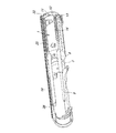
【選択図】図2A lock and striker assembly having a swivel and a rotary lockhead is provided.
An assembly for an inertially actuated weapon, which has a single function for all of the functions required for the correct operation of the weapon, such as locking, releasing, discharging the cartridge, and raising a restrike when returning to the lock. It is put together in an assembly. These functions are conventionally assigned to various elements assembled in the weapon. This lock and striker raising assembly with swivel 1 and rotating lockhead concentrates all the mass required for inertial movement on swivel 1, which is used to support weapon support structures such as weapons. Fully housed in the exterior or barrel extension, or in the breech. All of this gives a better balance and stability of the weapon, high reliability of operation, high structural simplicity, and ease of assembly and disassembly.
[Selection] Figure 2
Description
本発明は、旋回せん子および回転ロックヘッドを有するロックおよび再撃鉄起しアセンブリ、特に反跳の運動エネルギーを使用する慣性作動武器のためのアセンブリに関する。 The present invention relates to a lock and striker assembly having a swivel element and a rotary lockhead, and more particularly to an assembly for an inertial working weapon using recoil kinetic energy.
武器の反跳が、ばねの圧縮によってエネルギー貯蔵するために使用される慣性作動武器は、ずっと以前から公知である。このばねは、銃尾とロックヘッドとの間に配置され、その弾性反作用を利用して、再撃鉄起しの各種動作、すなわち閉鎖、開放、薬きょう引出しと排出、引き金アーミング(arming)、銃尾カバーばねの圧縮、銃身に新しい弾薬を挿入することによる閉鎖への戻り、にエネルギーが供給される。 Inertial working weapons where the weapon recoil is used to store energy by spring compression have long been known. This spring is placed between the breech and the lock head and uses its elastic reaction to perform various actions of raising the striker, i.e., closing, opening, pulling and discharging, triggering arming, breech Energy is supplied to the compression of the cover spring, return to closure by inserting new ammunition into the barrel.
従来、これらの機能はすべて、使用される技術的解決策に応じて、武器の異なる場所に取りつけられた各種要素によって実行されていた。 Traditionally, all these functions have been performed by various elements mounted at different locations on the weapon, depending on the technical solution used.
慣性質量が、主として、尾筒または銃身延長部内を滑動する旋回せん子と、結合ばね案内ピン、および銃床内部の管内で併進運動を行う対応するばねと、旋回せん子に継手(jointly)連結されて前記旋回せん子と結合ばね案内ピンとの間の連結具として作用する連結具とから成るシステムが存在する。 The inertial mass is jointly connected to the swivel, primarily a swivel slider that slides within the transition piece or barrel extension, a coupling spring guide pin, and a corresponding spring that translates within the tube inside the stock. In other words, there is a system consisting of a coupling that acts as a coupling between the swivel slider and the coupling spring guide pin.
慣性質量が、主として、旋回せん子と、該旋回せん子に接続された一つ以上のストラップによって構成される他のシステムが公知である。このストラップは、銃尾とともに滑動して、武器の案内ロッド内に配置された回復ばねを圧縮する。 Other systems are known in which the inertial mass is primarily comprised of a swirl and one or more straps connected to the swirl. The strap slides with the breech and compresses a recovery spring located in the weapon guide rod.
回転ロックヘッドを有する他のシステムも存在する。該システムにおいては、ロックヘッドと旋回せん子との併進運動を保証する連結具が、主として、銃身延長部または尾筒に備えられたガイドから成り、発射室のロックと開放のための旋回せん子に対するヘッドの回転および併進の組合せ運動がカムによって生成される。 There are other systems that have a rotating lockhead. In this system, the coupling that guarantees the translational movement of the lock head and the swivel consists mainly of a guide provided on the barrel extension or the tail tube, and the swivel for locking and releasing the firing chamber. A combined cam rotation and translation of the head is generated by the cam.
スパイク型のふたを有するシステムが存在する。該システムにおいては、銃尾とヘッドとの相対併進運動が、傾斜面に対して、銃身延長部に形成された受け座に係合するスパイクによって行われる。 There are systems with spike-type lids. In the system, the relative translational movement between the breech and the head is performed with respect to the inclined surface by a spike that engages a receiving seat formed in the barrel extension.
前記の先行システムはすべて、薬きょう排出のために、弾薬底部の排出体に対する衝撃を使用する。該排出体には、ばねによって、予荷重が与えられている。このばねも排出体も、銃身延長部または尾筒内に収容されている。 All of the preceding systems use an impact on the discharge body at the bottom of the ammunition for the discharge of the cartridge. The discharge body is preloaded by a spring. Both the spring and the discharge body are accommodated in the barrel extension or the tail tube.
前記各システムは、一般に、構造が複雑で高価であり、使用される要素の数が多いことのために信頼性が低く、保守が難しい。 Each of the above systems is generally complex and expensive, and is unreliable and difficult to maintain due to the large number of elements used.
本発明の包括的目的は、旋回せん子および回転閉鎖ヘッド(回転ロックヘッド)を有するロックおよび再撃鉄起しアセンブリ、特に反跳の運動エネルギーを使用する慣性作動武器のためのアセンブリであって、前記先行技術における欠点を有しないものを提供することである。 A general object of the present invention is a lock and re-strike assembly with a swivel and a rotary closure head (rotary lock head), in particular for an inertial working weapon using recoil kinetic energy, It is to provide what does not have the disadvantages of the prior art.
この包括的目的の範囲内で、本発明の一つの個別目的は、武器のより良いバランスと安定性とを与えるロックおよび再撃鉄起しアセンブリを提供することである。 Within this general purpose, one particular object of the present invention is to provide a lock and striker assembly that provides better balance and stability of the weapon.
本発明のもう一つの個別目的は、構造的に簡単で、動作における高い信頼性を保証するロックおよび再撃鉄起しアセンブリを提供することである。 Another particular object of the present invention is to provide a lock and striker assembly that is structurally simple and ensures high reliability in operation.
本発明のもう一つの個別目的は、集成と分解が簡単なロックおよび再撃鉄起しアセンブリを提供することである。 Another particular object of the present invention is to provide a lock and striker raising assembly that is easy to assemble and disassemble.
前記包括的目的および前記個別目的および以下で明らかになるその他の個別目的は、
旋回せん子および回転閉鎖ヘッドを有するロックおよび再撃鉄起しアセンブリ、特に反跳の運動エネルギーを利用する慣性作動武器のためのアセンブリであって、
携帯式武器の外装または銃身延長部(sheath or barrel extention)に挿入される単一本体を有し、
該単一本体が、前記武器の発射室の安定閉鎖のための閉鎖手段、開放手段、薬きょうを排出する手段、およびロックに戻るときの再撃鉄起し手段、を有し、
前記単一本体が、前記武器の支持構造物たとえば前記武器の外装または銃身延長部、または銃尾内に完全に収容される、
ことを特徴とするロックおよび再撃鉄起しアセンブリ、
によって達成される。
The general purpose and the individual purpose and other individual purposes that will become apparent below are:
A lock and re-strike assembly with a swivel and rotating closure head, in particular for an inertial working weapon utilizing recoil kinetic energy,
Has a single body that is inserted into the exterior or barrel extension of a portable weapon,
The single body has closing means for stable closing of the weapon's firing chamber, opening means, means for discharging the cartridge, and means for raising a restrike when returning to the lock;
The single body is fully contained within a support structure of the weapon, such as an exterior or barrel extension of the weapon, or a breech;
Lock and re-strike assembly, characterized by
Achieved by:
本発明の、旋回せん子および回転閉鎖ヘッドを有するロックおよび再撃鉄起しアセンブリは、慣性動作に必要な質量のすべてが旋回せん子に集中している。この集中は、武器の支持構造物たとえば外装または銃身延長部内に収容することによる。または、武器の銃尾が、システムの新しい発明的要素が集成される要素となっている。 The lock and re-strike assembly with the swivel and rotary closure head of the present invention concentrates all of the mass required for inertial motion on the swivel. This concentration is due to housing in a weapon support structure such as an exterior or barrel extension. Alternatively, the weapon's breech is the element where the new inventive elements of the system are assembled.
旋回せん子は、実際、回転ロックヘッドを収容する。この回転ロックヘッドは、シャンク上に備えられたらせんカムによって決定される回転運動によって武器の発射室の閉鎖と開放とを行う。これは、相互に集まる、回転閉鎖ヘッドおよび旋回せん子上に形成されるらせん傾斜面の寄与による。このようにして、ロック時に慣性システムのばねに接触したときの、旋回せん子の跳ね返りを避けることができる。 The swivel transducer actually houses the rotary lock head. The rotary lock head closes and opens the weapon firing chamber by a rotational movement determined by a helical cam provided on the shank. This is due to the contribution of the helically inclined surfaces formed on the rotary closure head and swivel element that gather together. In this way, it is possible to avoid rebound of the swivel element when it comes into contact with the inertial system spring during locking.
旋回せん子は、対応するばねとばね案内ピンとを有する武器の蹴子を収容する受け座を有する。該蹴子は、アセンブリ上での特殊な配置により、薬きょうを排出するほか、ロック動作の第一ステップにおける、補助回復ばねの機能、および武器の持ち上げと発射室への挿入時の弾薬の横方向ガイドの機能をも実行する。 The swivel element has a seat for receiving a weapon kicker having a corresponding spring and a spring guide pin. In addition to discharging the cartridge by a special arrangement on the assembly, the kicker functions as an auxiliary recovery spring in the first step of the locking operation, and the lateral direction of the ammunition when lifting and inserting the weapon into the firing chamber It also performs the guide function.
回復ばねと対応するばね案内ピンとは、旋回せん子上に取りつけられる。これらの要素により、開放と薬きょうの排出とのステップのあと、せん子アセンブリのロック位置への戻りが与えられるほかに、これらの要素の独特の形状とアセンブリ上での配置により、せん子アセンブリの再撃鉄起し行程の全体にわたる回転閉鎖ヘッドの案内、および、せん子アセンブリのロックへの戻りのための後続ステップ時の武器の持ち上げと発射室への挿入時の弾薬の上部接触点も与えられる。 The recovery spring and the corresponding spring guide pin are mounted on the swivel. These elements provide a return to the locked position of the assembly after the opening and dispensing steps, and the unique shape of the elements and their placement on the assembly allows the assembly of the assembly to be Guidance of the rotary closure head throughout the re-strike iron stroke and the upper contact point of ammunition during subsequent steps for lifting the weapon assembly and returning to the lock to the lock of the assembly is also given .
ダンパーが、直接、プレートと、回復ばね案内ピンおよび蹴子ばね案内ピンとにより、本発明の、旋回せん子と回転閉鎖ヘッドとを有するロックおよび再撃鉄起しアセンブリに連結される。このダンパーは、開放時の行程限界に対する旋回せん子の衝撃を減衰させ、このとき、アセンブリ全体が、常に、閉鎖ヘッドの回転のためのピボットのタブによって案内される。この閉鎖ヘッドも、旋回せん子に取りつけられており、武器の外装または銃身延長部の内部に備えられる受け座に係合する。 The damper is directly connected to the lock and striker raising assembly having the swivel and rotary closure head of the present invention by the plate and the recovery spring guide pin and the kick spring guide pin. This damper attenuates the impact of the swivel on the opening stroke limit, when the whole assembly is always guided by the pivot tab for the rotation of the closing head. This closing head is also attached to the swivel and engages a receiving seat provided in the exterior of the weapon or inside the barrel extension.
本発明のさらなる特徴と利点とは、添付の図面に非限定例として示す、本発明の好ましい非排他的実施形態の説明からさらにはっきりするであろう。 Further features and advantages of the present invention will become more apparent from the description of preferred non-exclusive embodiments of the present invention, given by way of non-limiting example in the accompanying drawings.
添付の図面に示すように、本発明の旋回せん子および再撃鉄起しアセンブリは、旋回せん子1を有し、該せん子内には、せん子反跳ばね2が挿入され、回転ロックヘッド3が取りつけられる。
As shown in the accompanying drawings, the swivel and reciprocating iron raising assembly of the present invention has a swivel 1 and a
回転ロックヘッド3は、ヘッド回転ピボット4によってせん子1に継手連結され、該ピボットは、武器の動作に必要なすべての可動質量をせん子上に集中させるために、せん子に継手連結され、ロックヘッドの円筒シャンク6に備えられたらせんカム5に係合する。
The
旋回せん子1のこの構成により、せん子質量の分離を最小限に抑え、したがってその質量を最大限に大きくすることができる。
With this configuration of the
次に、蹴子本体8を、旋回せん子1に挿入された受け座7に挿入する。
Next, the
前部に配向ぎざぎざ(milling)10を有する案内ピン9が、蹴子本体8に挿入される。
A
案内ピン9は、ばね案内ピン固定プレート11に固定され、順に、行程リミッターに対する旋回せん子の衝撃を弱めるためのダンパー12、開放時の旋回せん子端の行程が終るせん子接触プレート13、および蹴子ばね14を有している。
The
実質的に管状の蹴子本体8は、その前部に前部接触部15を有し、該接触部に対して、せん子の開放時に、武器からの排出のために薬きょうが衝突する。
The substantially
蹴子本体8の前部は、凹部16を有し、該凹部は、持ち上げと発射室への挿入時に弾薬の通過を可能にする。
The front part of the
蹴子本体8は、その後部に、二つのタブ17と18を有し、これらのタブは、集成されたとき、旋回せん子1に対する蹴子本体の長さ方向相対運動を定め、その回転を防止する。
The
ロックおよび再撃鉄起しアセンブリ上の蹴子8の位置は、ロック動作の第一のステップ時に、蹴子ばね14が補助回復ばねとしても作用することを可能にし、また、武器の持ち上げと発射室への挿入のステップにおいて、蹴子ばね案内ピン9が弾薬を横方向に案内することを可能にするようになっている。
The position of the
また、振動せん子1上には、回復ばね案内ピン19が、孔を通して挿入され、回復ばね20が後部の溝上に取りつけられ、旋回せん子1がロック位置に戻ることを可能にしている。
On the vibrating
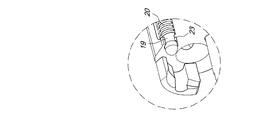
図3と4にさらにはっきり示すように、旋回せん子1に挿入された回復ばね案内ピン19は、回復ばね20を受けるせん子接触プレート13を通過する。
As more clearly shown in FIGS. 3 and 4, the recovery
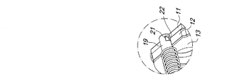
回復ばね案内ピン19は、ダンパー12を通過し、その後端21において、ばね案内ピン固定プレート11の凹部22によって、プレート11に係合する。
The recovery
図3と5にさらにはっきり示すように、回復ばね案内ピン19がその前部に有する突起23は、該ピンが凹部22に係合したときに、旋回せん子1の前部継手を構成する。この継手により、図2に示すように、ロックおよび再撃鉄起しアセンブリの全体が完全に集成される。
As more clearly shown in FIGS. 3 and 5, the
回復ばね案内ピン19の相対位置は、アセンブリが取りつけられたとき、その前部に備えられた平坦領域24が、該ピンを、薬きょうの排出前に、薬きょうのためのガイドとして、また持ち上げと発射室への挿入時の弾薬の上部接触点として、使用することを可能にする、ようになっている。
The relative position of the recovery
回復ばね案内ピン19は、旋回せん子1の開放および閉鎖行程の全体において、回転ロック3のためのガイドとしても作用する。
The recovery
発射ピン25が旋回せん子1に取りつけられ、対応するばね26に挿入され、回転ロックヘッド3、ヘッド回転ピボット4、およびせん子を通過している。発射ピン25は、留めピン27によって、せん子に強固に連結されている。
A
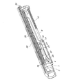
図2に明確に示すように、集成されたロックおよび再撃鉄起しアセンブリは、この特定のケースの外装または銃身延長部28では、武器の支持構造物内に取りつけられ、銃身延長部の内部に備えられたスロット30上のヘッド回転ピボット4のタブ29に係合して配向される。
As clearly shown in FIG. 2, the assembled lock and rehabilitation iron raising assembly is mounted within the support structure of the weapon at the exterior or
図6にはっきり示すように、撃鉄起しノブ31がアセンブリに挿入され、外装または銃身延長部28のスロット32を通って、旋回せん子1に取りつけられている。
As clearly shown in FIG. 6, a
スロット32は、せん子の開放行程超過位置(opening overtravel position)に備えられ、武器の正常動作時には、分解できないようになっている。
図6に明瞭に示すように、ロックおよび再撃鉄起しアセンブリの全体が外装または銃身延長部28に完全に取りつけられ、固定リング33によってそこに連結されると、回復ばね案内ピン19および蹴子ばね案内ピン9が、それぞれの前端34および10によって、外装または銃身延長部に形成された受け座35および36に係合し、ばね20および14と蹴子本体8の滑動のための二つの安定なガイドを構成し、かつ、外装または銃身延長部28の対応する受け座30に係合したヘッド回転ピボット4のタブ29に対する補助手段として、旋回せん子1の案内に寄与するようになっている(図2)。
As clearly shown in FIG. 6, when the entire lock and striker raising assembly is fully attached to the sheath or
図7を参照すると、旋回せん子1がロック位置にあるとき、また実質的な開放行程範囲においては、蹴子ばね14に荷重がかからず、蹴子本体8はせん子内に収容されている。
Referring to FIG. 7, when the
旋回せん子1の引込み行程の所定値から出発して、蹴子ばね14は、蹴子本体8にぶつかり、荷重を受けるようになり、蹴子本体8を前方に押して、該蹴子本体をロックヘッド3から突き出して(図8)、薬きょうを押し、薬きょうは外装または銃身延長部28から排出される。
Starting from a predetermined value of the retracting stroke of the
蹴子本体8の全行程は、旋回せん子1のスロット37内に係合し、旋回せん子1の回転を防止するタブ18によって定められ(図7)、その全工程において、蹴子本体8は、内部においては蹴子ばね案内ピン9によって案内され、外部においては、外装または銃身延長部28に作用するもう一つのタブ17によって案内される。
The entire stroke of the
開放行程時に、旋回せん子1は、対応するピン19によって案内される回復ばねを圧縮し、またある程度行程が進んだところから蹴子ばね14をも圧縮し、したがって図7および8に模式的に示すような後続のロックサイクルの実行に必要なエネルギーを蓄積する。
During the opening stroke, the
図8において、開放行程が終わると、旋回せん子1は、発射弾薬のエネルギーに応じて、大なり小なり激しく、固定リング33の内壁によって定められるその行程限界をたたき、衝撃エネルギーの一部をダンパー12に伝える。このダンパーは、せん子接触プレート13とばね案内ピン固定プレート11との間に配置されている。
In FIG. 8, when the opening stroke is completed, the
開放行程が終わると、せん子はその運動を逆転させ、回復ばね20と蹴子ばね14とによって偏倚され、閉鎖位置に戻り、新しい弾薬を持ち上げ、該弾薬は、蹴子ばね案内ピン9によって横方向に、回復ばね案内ピン19によって上方に案内され、発射室に挿入される。
At the end of the opening stroke, the spring reverses its movement and is biased by the
図9と10を参照すると、旋回せん子1のロック行程の最終段階において、閉鎖ヘッド3の回転が、その傾斜らせん面38が旋回せん子1に備えられた対応する傾斜らせん面39に接触することによって、起こる。
Referring to FIGS. 9 and 10, in the final stage of the locking stroke of the
この接触により、ヘッド3の回転とロックの完遂に必要なスピードが与えられ、またロック工程中に、蹴子ばね14の補助を受けつつ回復ばね20の推力によって得られたエネルギーの大部分が散逸する。
This contact gives the speed required to complete the rotation and locking of the
このように、ロックおよび再撃鉄起しアセンブリは、慣性作動武器システムに使用され、旋回せん子1は、その面40により、反跳ばね2を圧縮するには不十分なエネルギー、したがってロック時に旋回せん子1の反動および反跳運動を発生させるばねの弾性反作用が避けられるエネルギーで、反跳ばね2に接触する。
Thus, the lock and striker raising assembly is used in an inertially operated weapon system, and the
本発明による、旋回せん子および回転閉鎖ヘッドを有するロックおよび再撃鉄起しアセンブリは、再撃鉄起し、ロック、開放、薬きょう排出、および武器の正しい動作に必要なロックへの戻り、のサイクルに必要なすべての要素を、簡単かつコンパクトに、可動連結のみによって、単一のアセンブリにまとめるものである。 In accordance with the present invention, a lock and striker assembly with a swivel and rotary closure head is used to cycle a strike and release, lock, release, and return to lock required for proper weapon operation. All necessary elements are simply and compactly combined into a single assembly by a movable connection only.
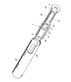
図1に模式的に示す分解と、図2に示す集成とは、可動連結のみによって相互連結されているので、道具の使用なしで手動で実行できる。 The disassembly shown schematically in FIG. 1 and the assembly shown in FIG. 2 are interconnected only by a movable connection and can therefore be performed manually without the use of tools.
実施においてわかったところでは、本発明は、ロック、開放、薬きょう抜取りと排出、再撃鉄起し、ロックへの戻りのすべての機能を、武器の外装または銃身延長部内に完全に集成される単一のロックおよび再撃鉄起しアセンブリにまとめるという、意図する包括的目的と個別目的とを達成するものである。 As found in practice, the present invention provides a single, fully assembled, all-encompassing function within the armor exterior or barrel extension for locking, opening, drug withdrawal and ejection, restrike and return to lock. To achieve the intended general purpose and individual purpose of bringing together the lock and re-strike assembly.
本発明のアセンブリの重要かつ利点のある特徴は、システムの慣性動作に必要なすべての質量が単一の旋回せん子本体にまとめられる、ということである。 An important and advantageous feature of the assembly of the present invention is that all the mass required for the inertial operation of the system is combined into a single swivel body.
本発明のロックおよび再撃鉄起しアセンブリのもう一つの利点は、対応するばねとばね案内ピンとを有する蹴子本体が旋回せん子に直接取りつけられ、したがってまた蹴子ばねが回復ばねとともにせん子のロック時の武器の再撃鉄起しにも寄与し、同時に、ばね案内ピンが持ち上げと武器の発射室への挿入時に弾薬に対する横方向ガイドとして作用する、ということである。 Another advantage of the lock and striker raising assembly of the present invention is that a kicker body having a corresponding spring and spring guide pin is attached directly to the swivel, so that the kicker spring together with the recovery spring is It also contributes to the re-strike of the weapon when locked, and at the same time, the spring guide pin acts as a lateral guide for ammunition when lifting and inserting the weapon into the firing chamber.
本発明のロックおよび再撃鉄起しアセンブリのもう一つの利点は、該アセンブリがせん子回復ばねと、旋回せん子に直接取りつけられた前記ばねに対応するばね案内ピンを有し、回復ばね案内ピンを、再撃鉄起しサイクル時の回転ロックヘッドのガイドとして、また武器の発射室への弾薬の挿入のための持ち上げと後続の案内時の弾薬の上部接触点として使用できるようになっている、ということである。 Another advantage of the lock and striker raising assembly of the present invention is that the assembly has a spring recovery spring and a spring guide pin corresponding to the spring mounted directly on the pivoting spring, the recovery spring guide pin Can be used as a guide for the rotary lockhead during re-strike cycles and as the upper contact point of ammunition for lifting and subsequent guidance for the insertion of ammunition into the weapon's firing chamber, That's what it means.
本発明のロックおよび再撃鉄起しアセンブリのもう一つの利点は、回転ロックヘッドと旋回せん子に備えられたらせん接触面によって、ロック時に回転ロックヘッドと旋回せん子との間に配置された慣性システムのばねに接触したときに、せん子の反跳が防がれる、ということである。 Another advantage of the lock and striker raising assembly of the present invention is that the helical contact surface provided on the rotary lock head and the swivel element allows inertia to be placed between the rotary lock head and the swivel element when locked. This means that the recoil of the transducer is prevented when it comes into contact with the spring of the system.
本発明のロックおよび再撃鉄起しアセンブリのもう一つの利点は、直接旋回せん子に連結されたダンパーによって、旋回せん子が開放行程限界に与える衝撃を弱めることができる、ということである。 Another advantage of the lock and striker assembly of the present invention is that a damper connected directly to the swivel can reduce the impact of the swivel on the open stroke limit.
実際、本発明のロックおよび再撃鉄起しアセンブリは、簡単かつコンパクトなシステムを提供し、該システムにおいては、武器に対する相対運動を行うすべての要素、すなわち慣性質量、反跳ばね、せん子回復ばね、蹴子、および対応するばねが、武器の外装または銃身延長部内に収容され、この外装または銃身延長部に対して軸方向に運動する。そのため、各種要素、たとえば連結機構およびベルト、ならびに旋回せん子を回復ばねに連結するのに必要なその他の細かい要素、を省いて簡単化することができる。それに反して、先行技術のシステムにおいては、これらの要素が、武器の銃床または案内ロッド内に配置されている。 In fact, the lock and striker raising assembly of the present invention provides a simple and compact system in which all elements that perform relative movement with respect to the weapon, ie, inertial mass, recoil spring, and spring recovery spring. , Kickers, and corresponding springs are housed within the armor or barrel extension and move axially relative to the armor or barrel extension. Therefore, various elements, such as the coupling mechanism and the belt, and other fine elements necessary for coupling the swivel element to the recovery spring can be omitted and simplified. On the other hand, in prior art systems, these elements are located in the stock or guide rod of the weapon.
本出願は、イタリア特許出願第MI2007A001474号(2007年7月20日出願)の優先権を主張するものである。同出願明細書の記載事項を参照されたい。 This application claims priority from Italian Patent Application No. MI2007A001474 (filed July 20, 2007). Please refer to the description of the application.
1 旋回せん子
2 せん子反跳ばね
3 回転ロックヘッド
4 回転ピボット
5 らせんカム
6 円筒シャンク
7 受け座
8 蹴子本体
9 案内ピン
10 配向ぎざぎざ
11 ばね案内ピン固定プレート
12 ダンパー
13 せん子接触プレート
14 蹴子ばね
15 8の前部接触部
16 凹部
17 タブ
18 タブ
19 回復ばね案内ピン
20 回復ばね
21 19の後端
22 凹部
23 突起
24 平坦領域
25 発射ピン
26 25に対応するばね
27 留めピン
28 外装または銃身延長部
29 タブ
30 スロット
31 撃鉄起しノブ
32 スロット
33 固定リング
34 前端
35 受け座
36 受け座
37 スロット
38 傾斜らせん面
39 傾斜らせん面
40 1の面
1 Swivel transducer
2 Spring recoil spring
3 Rotating lock head
4 Rotating pivot
5 Spiral cam
6 Cylindrical shank
7 Receiving seat
8 Kick body
9 Guide pin
10 Orientation Jagged
11 Spring guide pin fixing plate
12 Damper
13 Solder contact plate
14 Keg spring
15 8 front contacts
16 recess
17 tabs
18 tabs
19 Recovery spring guide pin
20 Recovery spring
21 19 Rear end
22 recess
23 Protrusion
24 Flat area
25 firing pin
Spring corresponding to 26 25
27 Fastening pin
28 Exterior or barrel extension
29 tabs
30 slots
31 hammering knob
32 slots
33 Retaining ring
34 Front end
35 cradle
36 cradle
37 slots
38 Inclined spiral surface
39 Inclined spiral surface
40 1 side
Claims (7)
携帯式武器の外装または銃身延長部に挿入される単一本体を有し、
該単一本体が、前記武器の発射室の安定閉鎖のための閉鎖手段、開放手段、薬きょうを排出する手段、およびロックに戻るときの再撃鉄起し手段、を有し、
前記単一本体が、前記武器の支持構造物たとえば前記武器の外装または銃身延長部、または銃尾内に完全に収容される、
ことを特徴とするロックおよび再撃鉄起しアセンブリ。 A lock and re-strike assembly with a swivel and rotating closure head, in particular for an inertial working weapon utilizing recoil kinetic energy,
Having a single body inserted into the exterior or barrel extension of a portable weapon;
The single body has closing means for stable closing of the weapon's firing chamber, opening means, means for discharging the cartridge, and means for raising a restrike when returning to the lock;
The single body is fully contained within a support structure of the weapon, such as an exterior or barrel extension of the weapon, or a breech;
Locking and re-strike assembly characterized by that.
Applications Claiming Priority (2)
| Application Number | Priority Date | Filing Date | Title |
|---|---|---|---|
| IT001474A ITMI20071474A1 (en) | 2007-07-20 | 2007-07-20 | CLOSING AND RESET UNIT WITH OSCILLATING SHUTTER AND ROTARY CLOSING HEAD, PARTICULARLY FOR WEAPONS WITH INERTIAL OPERATION USING THE KINETIC ENERGY OF RINCULO |
| ITMI2007A001474 | 2007-07-20 |
Publications (2)
| Publication Number | Publication Date |
|---|---|
| JP2009041902A true JP2009041902A (en) | 2009-02-26 |
| JP5334479B2 JP5334479B2 (en) | 2013-11-06 |
Family
ID=39865463
Family Applications (1)
| Application Number | Title | Priority Date | Filing Date |
|---|---|---|---|
| JP2008187632A Expired - Fee Related JP5334479B2 (en) | 2007-07-20 | 2008-07-18 | Lock and striker raising assembly with swivel and rotary lockhead, especially for inertial working weapons using recoil kinetic energy |
Country Status (10)
| Country | Link |
|---|---|
| US (1) | US7878107B2 (en) |
| EP (1) | EP2017565B1 (en) |
| JP (1) | JP5334479B2 (en) |
| CN (1) | CN101482380B (en) |
| BR (1) | BRPI0803524B1 (en) |
| EA (1) | EA014565B1 (en) |
| ES (1) | ES2698420T3 (en) |
| IL (1) | IL192753A (en) |
| IT (1) | ITMI20071474A1 (en) |
| MX (1) | MX2008009338A (en) |
Families Citing this family (17)
| Publication number | Priority date | Publication date | Assignee | Title |
|---|---|---|---|---|
| US8505227B2 (en) | 2009-03-24 | 2013-08-13 | Sturm, Ruger & Company, Inc. | Firearm with quick coupling barrel interlock system |
| US8490312B2 (en) | 2009-03-24 | 2013-07-23 | Sturm, Ruger & Company, Inc. | Quick coupling barrel system for firearm |
| US8479429B2 (en) | 2009-03-24 | 2013-07-09 | Sturm, Ruger & Company, Inc. | Firearm with quick coupling barrel system |
| US9057576B2 (en) | 2009-03-24 | 2015-06-16 | Sturm, Ruger & Company, Inc. | Firearm with quick coupling barrel system |
| US8356543B2 (en) | 2009-10-02 | 2013-01-22 | Defense Deisigns, LLC | Firearm firing mechanism |
| KR101147975B1 (en) | 2010-04-27 | 2012-05-24 | 태성정밀공업 주식회사 | Rope for carrying something anchor for musical instrument |
| US9488423B2 (en) | 2011-01-14 | 2016-11-08 | Arm West, Llc | Firearm systems and methods |
| AR104686A1 (en) * | 2015-05-22 | 2017-08-09 | Arm West Llc | FIREARM SYSTEMS AND METHODS |
| DE102015008797A1 (en) * | 2015-07-10 | 2017-01-12 | Rheinmetall Waffe Munition Gmbh | Case ejection device |
| US11569605B2 (en) | 2016-12-20 | 2023-01-31 | Te Connectivity Germany Gmbh | Contact device and contact system |
| WO2018117990A1 (en) * | 2016-12-23 | 2018-06-28 | Bahtiyar Tasyagan | Recoil-operated breech mechanism comprising a bolt carrier and rotatable bolt, and providing convenience in assembly-disassembly |
| US12085353B2 (en) * | 2017-01-06 | 2024-09-10 | F.M. Products Inc | Firearm |
| US12287167B2 (en) * | 2017-01-06 | 2025-04-29 | F.M. Products Inc | Firearm |
| US10677547B2 (en) | 2018-01-09 | 2020-06-09 | Sturm, Ruger & Company, Inc. | Pump action firearm with slide lock mechanism |
| US11098972B2 (en) * | 2018-03-20 | 2021-08-24 | Taylor. Weapons, Inc. | Recoil system for a self-loading firearm |
| US11549769B1 (en) * | 2019-07-31 | 2023-01-10 | Mark John Roth | Self-locking bolt system not requiring an external surface to lock to |
| CZ20214A3 (en) | 2021-01-08 | 2021-05-12 | Česká Zbrojovka A.S. | Assembly of the conclusion, the body of the conclusion and the ejector |
Citations (5)
| Publication number | Priority date | Publication date | Assignee | Title |
|---|---|---|---|---|
| JPS56500579A (en) * | 1979-04-11 | 1981-04-30 | ||
| US4279191A (en) * | 1979-04-11 | 1981-07-21 | Aimpoint Ab | Firearms |
| US6484430B1 (en) * | 1999-01-27 | 2002-11-26 | Zdf Import/Export, Inc. | Multi-lugged bolt carrier and barrel for rifles |
| US6971202B2 (en) * | 2003-01-27 | 2005-12-06 | Terrence Bender | Gas operated action for auto-loading firearms |
| US20060070288A1 (en) * | 2004-10-06 | 2006-04-06 | Fabbrica D'armi Pietro Beretta S.P.A. | Firearm with selection device for right or left-hand cartridge case ejection |
Family Cites Families (15)
| Publication number | Priority date | Publication date | Assignee | Title |
|---|---|---|---|---|
| US2645873A (en) * | 1950-01-31 | 1953-07-21 | Remington Arms Co Inc | Slide-actuated firearm with tilting locking block |
| US3447417A (en) * | 1966-03-09 | 1969-06-03 | Benelli Spa | Gun with a floating breech bolt |
| US3653140A (en) * | 1970-05-04 | 1972-04-04 | Remington Arms Co Inc | Firearm receiver mechanism with a roller detent pin for a telescopic breech-bolt |
| US3967403A (en) * | 1975-01-22 | 1976-07-06 | The United States Of America As Represented By The Secretary Of The Army | Manually-operated firearm with forward-moving barrel and automatic breech lock |
| US4615132A (en) * | 1983-03-28 | 1986-10-07 | Smith David E | Self loading pistol having a rear sight which secures a detachable breech block insert |
| IT1172795B (en) * | 1983-05-09 | 1987-06-18 | Benelli Armi Spa | CLOSURE WITH ROTARY HEAD AND SHUTTER FOR AUTOMATIC FIREARMS WITH INERTIAL OPERATION USING THE KINETIC ENERGY OF THE RECOIL |
| IT1210375B (en) * | 1987-03-12 | 1989-09-14 | Benelli Armi Spa | TUBULAR TANK CARTRIDGE FEEDING SYSTEM FOR RIFLES WITH SMOOTH BODY AND SEMI-AUTOMATIC MANUAL PUMP OPERATION OR CONVERTIBLE FROM ONE TO THE OTHER TYPE |
| EP0329797A1 (en) * | 1987-12-29 | 1989-08-30 | Renaud Kerbrat | Device for retarding the opening or locking action of a mobile firearm breech block |
| RU2066820C1 (en) * | 1993-06-28 | 1996-09-20 | Государственное предприятие "Ижевский механический завод" | Magazine gun bolt mechanism |
| US5651205A (en) * | 1996-03-29 | 1997-07-29 | Sturm, Ruger & Company, Inc. | Bolt and firing pin locking system for firearm |
| RO119094B1 (en) * | 1997-07-24 | 2004-03-30 | Izhmash Ojsc | Automatic weapon |
| US7107715B2 (en) * | 2003-05-23 | 2006-09-19 | Ra Brands, L.L.C. | Bolt assembly with locking system |
| DE60331785D1 (en) * | 2003-08-11 | 2010-04-29 | Meggitt Training Systems Inc | LOCK ARRANGEMENT FOR SHAFTS REFLECTIVE SIMULATOR |
| US7971379B2 (en) * | 2004-02-13 | 2011-07-05 | Rmdi, Llc | Firearm |
| BE1016821A3 (en) * | 2005-10-25 | 2007-07-03 | Browning Int Sa | IMPROVED SEMI-AUTOMATIC RIFLE |
-
2007
- 2007-07-20 IT IT001474A patent/ITMI20071474A1/en unknown
-
2008
- 2008-07-08 EP EP08012289.8A patent/EP2017565B1/en active Active
- 2008-07-08 ES ES08012289T patent/ES2698420T3/en active Active
- 2008-07-08 US US12/217,765 patent/US7878107B2/en active Active
- 2008-07-10 IL IL192753A patent/IL192753A/en active IP Right Grant
- 2008-07-18 EA EA200801578A patent/EA014565B1/en unknown
- 2008-07-18 JP JP2008187632A patent/JP5334479B2/en not_active Expired - Fee Related
- 2008-07-18 MX MX2008009338A patent/MX2008009338A/en active IP Right Grant
- 2008-07-18 CN CN2008101756631A patent/CN101482380B/en not_active Expired - Fee Related
- 2008-07-21 BR BRPI0803524-5A patent/BRPI0803524B1/en not_active IP Right Cessation
Patent Citations (5)
| Publication number | Priority date | Publication date | Assignee | Title |
|---|---|---|---|---|
| JPS56500579A (en) * | 1979-04-11 | 1981-04-30 | ||
| US4279191A (en) * | 1979-04-11 | 1981-07-21 | Aimpoint Ab | Firearms |
| US6484430B1 (en) * | 1999-01-27 | 2002-11-26 | Zdf Import/Export, Inc. | Multi-lugged bolt carrier and barrel for rifles |
| US6971202B2 (en) * | 2003-01-27 | 2005-12-06 | Terrence Bender | Gas operated action for auto-loading firearms |
| US20060070288A1 (en) * | 2004-10-06 | 2006-04-06 | Fabbrica D'armi Pietro Beretta S.P.A. | Firearm with selection device for right or left-hand cartridge case ejection |
Also Published As
| Publication number | Publication date |
|---|---|
| IL192753A (en) | 2012-03-29 |
| EA200801578A1 (en) | 2009-02-27 |
| MX2008009338A (en) | 2009-03-05 |
| JP5334479B2 (en) | 2013-11-06 |
| US7878107B2 (en) | 2011-02-01 |
| ITMI20071474A1 (en) | 2009-01-21 |
| EA014565B1 (en) | 2010-12-30 |
| EP2017565B1 (en) | 2018-08-29 |
| CN101482380B (en) | 2013-09-25 |
| EP2017565A3 (en) | 2015-04-08 |
| BRPI0803524B1 (en) | 2020-10-20 |
| US20090019754A1 (en) | 2009-01-22 |
| CN101482380A (en) | 2009-07-15 |
| EP2017565A2 (en) | 2009-01-21 |
| BRPI0803524A2 (en) | 2009-08-25 |
| ES2698420T3 (en) | 2019-02-04 |
| IL192753A0 (en) | 2009-08-03 |
Similar Documents
| Publication | Publication Date | Title |
|---|---|---|
| JP5334479B2 (en) | Lock and striker raising assembly with swivel and rotary lockhead, especially for inertial working weapons using recoil kinetic energy | |
| CN102245997B (en) | Delayed blowback firearms with novel mechanisms for control of recoil and muzzle climb | |
| EP3294691B1 (en) | Firing device | |
| EP2647946B1 (en) | Semiautomatic bullet firing mechanism for a compressed gas gun and toy gun using it | |
| US5736667A (en) | Automatic firearm arranged for high safety and rapid dismantling | |
| US5502914A (en) | Striker cocking and firing mechanism for a handgun | |
| US5939659A (en) | Gas operated forward actuating pistol | |
| WO2017117208A1 (en) | Firing control system for firearm | |
| JP2009041901A (en) | Modular portable weapons | |
| US7467581B2 (en) | Semi-automatic rifle | |
| US11774198B2 (en) | Rifle with recoil group | |
| US20090049730A1 (en) | Adaptable firing pin assembly for a bolt action firearm | |
| KR101079169B1 (en) | mechanical Revolver style tear gas bomb launcher | |
| RU2241941C2 (en) | Firearm | |
| ES2321929T3 (en) | SMALL FIREARM WITH LOCKED LOCK. | |
| RU2077690C1 (en) | Self-loading pistol | |
| KR102812247B1 (en) | Breach block assembly for firearms and related firearms | |
| US5808230A (en) | Breechlock for automatic or semi-automatic weapons | |
| HK1123350A (en) | Locking and recocking assembly with swivel breech-lock and rotating locking head, particularly for inertially-actuated weapons using the kinetic energy of recoil | |
| KR100726193B1 (en) | Rotary Key Lock Single Recoil Launcher | |
| HK1123350B (en) | Locking and recocking assembly with swivel breech-lock and rotating locking head, particularly for inertially-actuated weapons using the kinetic energy of recoil | |
| US20080120887A1 (en) | Hunting and Sporting Firearm | |
| KR101835196B1 (en) | System for percussion of cannonball of cannon | |
| AU2005266850B2 (en) | An adaptable firing pin asssembly for a bolt action firearm | |
| RU2069298C1 (en) | Multibarrel self-cocking pistol |
Legal Events
| Date | Code | Title | Description |
|---|---|---|---|
| A621 | Written request for application examination |
Free format text: JAPANESE INTERMEDIATE CODE: A621 Effective date: 20110407 |
|
| A977 | Report on retrieval |
Free format text: JAPANESE INTERMEDIATE CODE: A971007 Effective date: 20121031 |
|
| A131 | Notification of reasons for refusal |
Free format text: JAPANESE INTERMEDIATE CODE: A131 Effective date: 20121106 |
|
| A521 | Request for written amendment filed |
Free format text: JAPANESE INTERMEDIATE CODE: A523 Effective date: 20130128 |
|
| TRDD | Decision of grant or rejection written | ||
| A01 | Written decision to grant a patent or to grant a registration (utility model) |
Free format text: JAPANESE INTERMEDIATE CODE: A01 Effective date: 20130709 |
|
| A61 | First payment of annual fees (during grant procedure) |
Free format text: JAPANESE INTERMEDIATE CODE: A61 Effective date: 20130730 |
|
| R150 | Certificate of patent or registration of utility model |
Ref document number: 5334479 Country of ref document: JP Free format text: JAPANESE INTERMEDIATE CODE: R150 Free format text: JAPANESE INTERMEDIATE CODE: R150 |
|
| R250 | Receipt of annual fees |
Free format text: JAPANESE INTERMEDIATE CODE: R250 |
|
| R250 | Receipt of annual fees |
Free format text: JAPANESE INTERMEDIATE CODE: R250 |
|
| R250 | Receipt of annual fees |
Free format text: JAPANESE INTERMEDIATE CODE: R250 |
|
| R250 | Receipt of annual fees |
Free format text: JAPANESE INTERMEDIATE CODE: R250 |
|
| R250 | Receipt of annual fees |
Free format text: JAPANESE INTERMEDIATE CODE: R250 |
|
| R250 | Receipt of annual fees |
Free format text: JAPANESE INTERMEDIATE CODE: R250 |
|
| R250 | Receipt of annual fees |
Free format text: JAPANESE INTERMEDIATE CODE: R250 |
|
| R250 | Receipt of annual fees |
Free format text: JAPANESE INTERMEDIATE CODE: R250 |
|
| LAPS | Cancellation because of no payment of annual fees |