JP2009049999A - Common protocols and routing schemes for space data processing networks - Google Patents
Common protocols and routing schemes for space data processing networks Download PDFInfo
- Publication number
- JP2009049999A JP2009049999A JP2008207815A JP2008207815A JP2009049999A JP 2009049999 A JP2009049999 A JP 2009049999A JP 2008207815 A JP2008207815 A JP 2008207815A JP 2008207815 A JP2008207815 A JP 2008207815A JP 2009049999 A JP2009049999 A JP 2009049999A
- Authority
- JP
- Japan
- Prior art keywords
- endpoint
- protocol
- layer
- network
- switch
- Prior art date
- Legal status (The legal status is an assumption and is not a legal conclusion. Google has not performed a legal analysis and makes no representation as to the accuracy of the status listed.)
- Pending
Links
Images




Classifications
-
- G—PHYSICS
- G06—COMPUTING OR CALCULATING; COUNTING
- G06F—ELECTRIC DIGITAL DATA PROCESSING
- G06F13/00—Interconnection of, or transfer of information or other signals between, memories, input/output devices or central processing units
- G06F13/38—Information transfer, e.g. on bus
- G06F13/382—Information transfer, e.g. on bus using universal interface adapter
- G06F13/385—Information transfer, e.g. on bus using universal interface adapter for adaptation of a particular data processing system to different peripheral devices
-
- H—ELECTRICITY
- H04—ELECTRIC COMMUNICATION TECHNIQUE
- H04L—TRANSMISSION OF DIGITAL INFORMATION, e.g. TELEGRAPHIC COMMUNICATION
- H04L67/00—Network arrangements or protocols for supporting network services or applications
- H04L67/01—Protocols
- H04L67/12—Protocols specially adapted for proprietary or special-purpose networking environments, e.g. medical networks, sensor networks, networks in vehicles or remote metering networks
-
- H—ELECTRICITY
- H04—ELECTRIC COMMUNICATION TECHNIQUE
- H04L—TRANSMISSION OF DIGITAL INFORMATION, e.g. TELEGRAPHIC COMMUNICATION
- H04L69/00—Network arrangements, protocols or services independent of the application payload and not provided for in the other groups of this subclass
- H04L69/18—Multiprotocol handlers, e.g. single devices capable of handling multiple protocols
Landscapes
- Engineering & Computer Science (AREA)
- Theoretical Computer Science (AREA)
- Computer Networks & Wireless Communication (AREA)
- Signal Processing (AREA)
- General Health & Medical Sciences (AREA)
- Computing Systems (AREA)
- Health & Medical Sciences (AREA)
- Medical Informatics (AREA)
- Physics & Mathematics (AREA)
- General Engineering & Computer Science (AREA)
- General Physics & Mathematics (AREA)
- Computer Security & Cryptography (AREA)
- Communication Control (AREA)
- Data Exchanges In Wide-Area Networks (AREA)
Abstract
Description
本出願は、「VIRTUAL NETWORK ARCHITECTURE FOR SPACE DATA PROCESSING」(本明細書では「H0015888−5802出願」とも呼ばれる)という題名を有する米国特許出願第11/838,023号(整理番号H0015888−5802)に関する。 This application is related to US patent application Ser. No. 11 / 838,023 (reference number H0015888-5802) having the title “VIRTUAL NETWORK ARCHITECTURE FOR SPACE DATA PROCESSING” (also referred to herein as the “H0015888-5802 application”).
現在、新しいデータ処理アーキテクチャがスペース用途向けに開発されるとき、それぞれのデータ処理アーキテクチャは、極めて専門化され、個別のシステム相互接続技術にしばしば頼る。各顧客が様々なシステムレベルの性能要求を有するので、それぞれのシステム相互接続設計はゼロから始める。 Currently, as new data processing architectures are developed for space applications, each data processing architecture is highly specialized and often relies on individual system interconnection technologies. Since each customer has different system level performance requirements, each system interconnect design starts from scratch.
ありとあらゆる任務に対して新しい技術を採用するステップに関連した高いリスクがあり、ネットワーク技術は、技術が高くなるにつれてより高い性能へのパスを残さないと所与のプロトコルに対するサポートが廃れる可能性があるので陳腐化に対して脆弱である。さらに、1つのプロトコルの種類だけが各物理的ネットワークファブリック上で実行される可能性があり、複雑なスペースシステムがデータトラフィック、制御、および管理などの個別の機能のために個別の物理的ネットワークをしばしば必要とするステップを意味する。機能ごとの個別の物理的ネットワークの要求はシステムの複雑さ、サイズ、重さ、および電力をさらに増大する。 There is a high risk associated with adopting new technologies for every mission, and network technologies may lose support for a given protocol without leaving a path to higher performance as the technologies become higher So it is vulnerable to obsolescence. In addition, only one protocol type can be run on each physical network fabric, and complex space systems can use separate physical networks for individual functions such as data traffic, control, and management. Often means a necessary step. Individual physical network requirements for each function further increase system complexity, size, weight, and power.
第1の態様では、複数のネットワークプロトコルの種類をサポートするネットワーク要素を通信できるように結合する方法は、ネットワークエンドポイント内のエンドポイント・フレキシブル・インターフェース層でプロトコルスタックの上位レベルからの複数のネットワークプロトコルの種類を有する入力を受信するステップ、プロトコルスタックの上位レベルとプロトコルスタック内の共通の下位レベルとの間のエンドポイント・フレキシブル・インターフェース層で入力をマッピングするステップ、および物理層に複数のネットワークプロトコルの種類をインターフェースするために共通の下位レベルのプロトコル層を実現するステップを備え、その結果、ネットワークの少なくとも2つのエンドポイントが通信できるように結合される。 In a first aspect, a method for communicatively coupling network elements that support a plurality of network protocol types includes a plurality of networks from a higher level of the protocol stack at an endpoint flexible interface layer within the network endpoint. Receiving input having a protocol type, mapping input at an endpoint flexible interface layer between an upper level of the protocol stack and a common lower level in the protocol stack, and multiple networks in the physical layer Providing a common lower level protocol layer for interfacing protocol types, so that at least two endpoints of the network are coupled to communicate .
一般的方法により、様々な説明される特徴が、基準化するために書かれるのではなく本発明に関連する特徴を強調するために書かれている。参照文字は図およびテキスト中で同様の要素を示す。 In a general manner, the various described features are not written to scale, but rather to emphasize features relevant to the present invention. Reference characters indicate similar elements in figures and text.
下記の詳細な説明では、本明細書の一部を形成する添付図面が参照され、本発明が実施されることができる特定の例示の実施形態が説明のために示される。これらの実施形態は、当業者が本発明を実施するステップができるように十分に詳細に説明され、他の実施形態が使用されることができ、論理的、機械的、および電気的変更が本発明の範囲から逸脱するステップなくなされることは理解されるべきである。したがって、下記の詳細な説明は限定する意味にとられるべきではない。 In the following detailed description, reference is made to the accompanying drawings that form a part hereof, and in which is shown by way of illustration specific illustrative embodiments in which the invention may be practiced. These embodiments are described in sufficient detail to enable those skilled in the art to practice the invention, other embodiments may be used, and logical, mechanical, and electrical changes may be made to the present. It should be understood that this may be done without departing from the scope of the invention. The following detailed description is, therefore, not to be taken in a limiting sense.
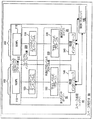
図1は、本発明によるそれぞれが通信できるように結合されたエンドポイント10および20内のプロトコルスタック100および200の1つの実施形態の構成図である。ネットワークエンドポイント10および20は、本明細書では「エンドポイント10および20」とも呼ばれる。スペース用途向けのデータ処理アーキテクチャは、宇宙飛行体50内に収容されたスペース処理システム40内で示される。スペース処理システム40は、本明細書では「ネットワーク40」と呼ばれる。スペース処理システム40は、本明細書では「第1のエンドポイント10および第2のエンドポイント20」とも呼ばれる複数のネットワーク要素10および20を含む。第1のエンドポイント10および第2のエンドポイント20は、物理層の各物理インターフェース140および240を介して互いに通信できるように結合されている。物理インターフェース140および240は、それぞれが複数のプロトコルを有する入力を受信するおよび/または送信するために複数の物理的相互接続を備える。本明細書で定義されるように、用語「入力」および「複数の入力」は、プロトコルスタックの層で受信され、プロトコルスタックの層から送信される1つのデータ、複数のデータ、信号、および/またはデータおよび/または信号を示す情報を表すために使用される。したがって、用語入力は入力信号および出力信号の全体を表す。
FIG. 1 is a block diagram of one embodiment of protocol stacks 100 and 200 within
管理プロセッサ190は、スペース処理システム40におけるネットワーク要素10および20を管理する。管理プロセッサ190は、第1のエンドポイント10および第2のエンドポイント20を管理するためにそれぞれの物理インターフェース140および240を介して第1のエンドポイント10および第2のエンドポイント20に通信できるように結合される。この実施形態の1つの実装形態では、管理プロセッサ190はスペース処理システム40におけるエンドポイントのうちの1つである。
The
各ネットワークエンドポイント10および20におけるプロトコルスタック100および200のそれぞれは、複数の下位レベルの相互接続プロトコル330(本明細書では「共通の下位レベルのプロトコル層330」とも呼ばれる)、複数の上位レベルのネットワークプロトコル310(本明細書ではネットワーク・プロトコル・スタックの上位レベル310とも呼ばれる)、および複数の下位レベルの相互接続プロトコルと複数の上位レベルのネットワークプロトコルと間に位置するフレキシブルインターフェース層320を含む。それぞれの上位レベルのネットワークプロトコルはそれぞれの種類のデータトラフィックと関連付けられている。図1に示すように、第1のエンドポイント10のプロトコルスタック100は、ネットワーク・プロトコル・スタック100の上位レベル310のアプリケーション層などの上位レベルのネットワークプロトコル層(ULNPL)110、フレキシブルインターフェース層320におけるエンドポイント・フレキシブル・インターフェース層(エンドポイントフレキシブルIL)120、共通の下位レベルのプロトコル層330における下位レベルのプロトコル130を含む。同様に、第2のエンドポイント20のプロトコルスタック200は、ネットワーク・プロトコル・スタック200の上位レベル310における上位レベルのネットワークプロトコル層210、フレキシブルインターフェース層320のエンドポイント・フレキシブル・インターフェース層220、および共通の下位レベルのプロトコル層330における下位レベルのプロトコル230を含む。この実施形態の1つの実装形態では、下位レベルのプロトコル130は下位レベルのシリアルプロトコル130である。
Each of the protocol stacks 100 and 200 at each
下位レベルのプロトコル130および230などの下位レベルの相互接続プロトコルは、スペース処理システム40の複数のネットワーク要素のそれぞれに共通である。したがって、下位レベルのプロトコル130および230は同一のプロトコルを含む。共通の下位レベルのプロトコル層330は、複数の上位レベルのネットワークプロトコルが共存するプラットフォームを提供する。
Lower level interconnection protocols, such as
フレキシブルインターフェース層は、フレキシブルインターフェース層320の複数の上位レベルのプロトコルを第1のエンドポイント10および第2のエンドポイント20などのネットワーク要素の共通の下位レベルのプロトコル層330における複数の下位レベルの相互接続プロトコルのうちの関連の1つにマッピングする。下位レベルのプロトコルは、物理トランスポート媒体および上位レベルのプロトコルと無関係である。この実施形態の1つの実装形態では、図1に示されるようにすべてのネットワーク要素がネットワークエンドポイントである。この実施形態の1つの実装形態では、スペース処理システム40におけるネットワーク要素は密結合の埋込みシステムを備える。この実施形態の他の実装形態ではネットワーク要素は、宇宙飛行体50におけるスペース処理システムではない処理システム内にある。この実施形態の他の実装形態では、ネットワーク要素はスペース処理システムではない密結合の埋込みシステムを備える。
The flexible interface layer converts the plurality of higher level protocols of the
図2Aおよび図2Bは、本発明によるエンドポイントおよびスイッチを通信できるように結合するプロトコルスタックの実施形態の構成図である。図2Aは、本発明によるスイッチ30におけるプロトコルスタック300を介して通信できるように結合された各ネットワークエンドポイント10および20内のプロトコルスタック100および200の1つの実施形態の構成図である。数字105によって全体的に表されるネットワーク要素の第1の部分は、それぞれがフレキシブルインターフェース層321においてエンドポイント・フレキシブル・インターフェース層120および220のそれぞれを有するネットワークエンドポイント10および20などのネットワークエンドポイントを含む。数字106によって全体的に表されるネットワーク要素の第2の部分は、スイッチ30などのスイッチを含む。各スイッチ30は、フレキシブルインターフェース層321におけるフレキシブルルーティング層(フレキシブルRL)160を有する。この実施形態の1つの実装形態では、ネットワーク要素10および20ならびにスイッチ30は宇宙飛行体50におけるスペース処理システムにある。
2A and 2B are block diagrams of an embodiment of a protocol stack that communicatively couples endpoints and switches according to the present invention. FIG. 2A is a block diagram of one embodiment of protocol stacks 100 and 200 within each
管理プロセッサ190は、ネットワークエンドポイント10および20ならびにスイッチ30などのネットワーク要素を管理する。管理プロセッサ190は、第1のエンドポイント10、スイッチ30、および第2のエンドポイント20を管理するために第1のエンドポイント10、スイッチ30、および第2のエンドポイント20の物理インターフェース140、180、および240に通信できるように結合されている。この実施形態の1つの実装形態では、管理プロセッサ190はスイッチ30の物理インターフェース180に通信できるように結合されており、管理プロセッサ190はスイッチ30を介して第1のエンドポイント10および第2のエンドポイント20を間接的に管理する。
図2Aに示されるように、スイッチ30のプロトコルスタック300は、フレキシブルインターフェース層321におけるフレキシブルルーティング層160および共通の下位レベルのプロトコル層331における下位レベルのプロトコル170を含む。各ネットワークエンドポイント10および20におけるプロトコルスタック100および200は、図1を参照して上述されている。第1のエンドポイント10および第2のエンドポイント20のそれぞれのプロトコルスタック100および200は、フレキシブルインターフェース層321にエンドポイント・フレキシブル・インターフェース層120および220、共通の下位レベルのプロトコル層331に下位レベルのプロトコル130および230を含む。
As shown in FIG. 2A, the
下位レベルのプロトコル130および230は、スイッチ30内の下位レベルのプロトコル170と共通した少なくとも1つのプロトコルを有するが、下位レベルのプロトコル130および230は互いに共通した何らかのプロトコルを有する必要はない。共通の下位レベルのプロトコル層331は、複数の上位レベルのネットワークプロトコルが共存するプラットフォームを提供する。この実施形態の1つの実装形態では、単一の標準的下位レベルのプロトコルが、システムが電源オンされるときに各プロトコルスタックの共通の下位レベルのプロトコル層上で実行される。
The
スイッチ30内のフレキシブルルーティング層160は、第1のエンドポイント10から第2のエンドポイント20に入力をルーティングする。スイッチ30内のフレキシブルルーティング層160は、受信された入力を第2のエンドポイントにマッピングし、マッピングに基づいてスイッチ30は、物理インターフェース180を介して入力を送信する。物理インターフェース180は、それぞれの複数のプロトコルで入力を受信するおよび/または送信するために少なくとも1つの物理的相互接続を備える。この実施形態の1つの実装形態では、同一の物理的相互接続が複数の上位レベルのプロトコルのために使用される。この実施形態の他の実装形態では、同一の物理的相互接続がまた、いくつかの下位レベルのプロトコルのために使用される。この実施形態の他の実装形態では、いくつかの下位レベルのプロトコルは他の下位レベルのプロトコルと異なる物理的相互接続を使用する。
A
図2Bは、本発明による第1のスイッチ30におけるプロトコルスタック300を介して第2のスイッチ32に通信できるように結合された各ネットワークエンドポイント10におけるプロトコルスタック100の1つの実施形態の構成図である。図2Bは、エンドポイント10が第1のスイッチ30とも呼ばれるスイッチ30を介して第2のスイッチ32と通信できるように結合されているという点で図2Aと異なる。第2のスイッチ32は、図2Aを参照して上述された第1のスイッチ30と構造上同様である。第2のスイッチ32の共通の下位レベルのプロトコル層331における下位レベルのプロトコル172は、第1のスイッチ30の共通の下位レベルのプロトコル層331における下位レベルのプロトコル170と同様である。同様に、第2のスイッチ32におけるフレキシブルルーティング層162は、第1のスイッチ30におけるフレキシブルルーティング層160と同様である。この実施形態の1つの実装形態では、第2のスイッチ32に送信される入力は、第3のスイッチまたは第2のエンドポイントなどの他のネットワーク要素に送信される。この実施形態の他の実装形態では、第2のスイッチ32に送信される入力は、第2のスイッチ32で格納されまたは実現され、他の任意のネットワーク要素に送信されない。
FIG. 2B is a block diagram of one embodiment of a
管理プロセッサ190は、ネットワークエンドポイント10ならびにスイッチ30および32などのネットワーク要素を管理する。管理プロセッサ190は、エンドポイント10、第1のスイッチ30、および第2のスイッチ32を直接管理するためにエンドポイント10、第1のスイッチ30、および第2のスイッチ32のそれぞれの物理インターフェース140、180、および182に通信できるように結合されている。この実施形態の1つの実装形態では、管理プロセッサ190は第1のスイッチ30の物理インターフェース180に通信できるように結合されており、管理プロセッサ190は第1のスイッチ30を介してエンドポイント10および第2のスイッチ32を間接的に管理する。この実施形態の1つの実装形態では、2つのスイッチは第3のスイッチを介して互いに通信できるように結合されている。
図3は、本発明によるエンドポイント・プロトコル・スタック101の1つの実施形態の構成図である。物理インターフェースは電気的インターフェース141である。プロトコルスタックの上位レベル310は、市版されているネットワークプロトコルRapidIO111、Gigibit Ethernet(GigE)112、SpaceWire113、およびInfiniBand Architecture(IBA)114を使用するアプリケーションを含む。図3の共通の下位レベルのプロトコル層331は、Interlaken131およびSystem Packet Interface−Scalable(SPI−S)132を含む市版されているプロトコルを含む。
FIG. 3 is a block diagram of one embodiment of an
図4は、本発明によるスイッチ・プロトコル・スタック301の1つの実施形態の構成図である。物理インターフェースは電気的インターフェース181である。フレキシブルルーティング層160の上方にスイッチ・プロトコル・スタック301のレベルがない。図3の共通の下位レベルのプロトコル層331はInterlaken131およびSPI−S132を含む市販されているプロトコルを含み、その結果、スイッチ・プロトコル・スタック301は、図3に示されるエンドポイント・プロトコル・スタック101と互換性がある。
FIG. 4 is a block diagram of one embodiment of a
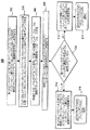
図5は、複数のネットワークプロトコルの種類をサポートするネットワーク要素を通信できるように結合するための方法500の1つの実施形態のフロー図である。方法500は図1および図2の例示のプロトコルスタック100、200、および300を参照して説明されているが、方法500が、この文書を読む当業者によって理解されることができる通信できるように結合されたプロトコルスタックの他の実施形態を使用して実現されることができることは理解されるべきである。
FIG. 5 is a flow diagram of one embodiment of a
ブロック502では、ネットワークエンドポイントは、ネットワークエンドポイント内のエンドポイント・フレキシブル・インターフェース層でプロトコルスタックの上位レベルからの複数のネットワークプロトコルの種類を有する入力を受信する。本明細書で定義されるように、複数のネットワークプロトコルの種類を有する入力は複数のネットワークプロトコルの種類を有する1つまたは複数の入力を含む。この実施形態の1つの実装形態では、ネットワークエンドポイント10におけるエンドポイント・フレキシブル・インターフェース層120がプロトコルスタック100の上位レベルのネットワークプロトコル層110から複数のネットワークプロトコルの種類を有する入力を受信する。例示の場合ではネットワークエンドポイント10は、RapidIO111、Gigibit Ethernet(GigE)112、SpaceWire113、およびInfiniBand Architecture(IBA)114(図3)をサポートするアプリケーションから入力を受信する。
In
ブロック504では、ネットワークエンドポイントにおけるエンドポイント・フレキシブル・インターフェース層が、プロトコルスタックの上位レベルとプロトコルスタックにおける共通の下位レベルとの間で入力をマッピングする。この実施形態の1つの実装形態では、第1のネットワークエンドポイント10におけるエンドポイント・フレキシブル・インターフェース層120は、プロトコルスタック100の上位レベル310とプロトコルスタック100内の共通の下位レベル331(図2A)との間で入力をマッピングする。ブロック506では、複数のネットワークプロトコルの種類が共通の下位レベルのプロトコル層を用いて物理層内の物理インターフェースにインターフェースされ、その結果、ネットワークの少なくとも2つのエンドポイントが通信できるように結合される。この実施形態の1つの実装形態では、共通の下位レベルのプロトコル層331が第1のネットワークエンドポイント10の物理インターフェース140に複数のネットワークプロトコルの種類をインターフェースするために実現され、その結果、第1のネットワークエンドポイント10は第2のネットワークエンドポイント20に通信できるように結合される。ブロック508では、エンドポイント・フレキシブル・インターフェース層から受信された入力は、第1の物理インターフェースを介してネットワーク要素から送信される。この実施形態の1つの実装形態では、エンドポイント・フレキシブル・インターフェース層120から受信された入力は、物理インターフェース140を介して第1のネットワーク要素10から送信される。この実施形態の1つの実装形態では、図1または図2の管理プロセッサ190は第1のエンドポイント10を第2のエンドポイント20に通信できるように結合するために命令を送信する。
At
ブロック510では、第1のエンドポイント10がスイッチに通信できるように結合されているか否かが決定される。この実施形態の1つの実装形態では、管理プロセッサ190は、ネットワークエンドポイントがスイッチに通信できるように結合されているか否かを把握する。ネットワークエンドポイントがスイッチに通信できるように結合されている場合、フローはブロック512に進む。ブロック512では、第1のエンドポイントから送信された入力が物理層におけるスイッチの物理インターフェースで受信される。この実施形態の1つの実装形態では、第1のエンドポイント100から送信された入力は、スイッチ30の物理インターフェース180(図2A)で受信される。ブロック514では、方法500のフローは図6の方法600のブロック602に導かれる。
At
ネットワークエンドポイントがスイッチに通信できるように結合されていない場合、ネットワークエンドポイントは他のネットワークエンドポイントに通信できるように直接結合されている。この場合、フローはブロック510からブロック516に進む。ブロック516では、第1のエンドポイント・フレキシブル・インターフェース層から送信された入力は、第2のエンドポイントの物理層における第2の物理インターフェースで受信される。この実施形態の1つの実装形態では、物理インターフェース140を介して第1のエンドポイント・フレキシブル・インターフェース層120から送信された入力は、第2のエンドポイント20の第2の物理インターフェース240(図1)で受信される。ブロック518では、方法500のフローは図7の方法700のブロック702に導かれる。この実施形態の1つの実装形態では、スイッチにおいてプロトコルスタックは図4に示されるプロトコルスタックである。
If the network endpoint is not coupled to communicate with the switch, the network endpoint is directly coupled to communicate with other network endpoints. In this case, flow proceeds from
図6は、本発明によるスイッチ・プロトコル・スタック内の共通の下位レベルのプロトコル層を実現するための方法600の1つの実施形態のフロー図である。方法600は、第1のエンドポイントがスイッチに通信できるように結合されるときにおよび第1のエンドポイントからの入力がスイッチで受信された後に実現される。方法600は、図2Aの例示のプロトコルスタック100、200、および300を参照して説明されているが、方法600が、この文書を読む当業者によって理解されることができる通信できるように結合されたネットワークエンドポイントおよびスイッチの他の実施形態を使用して実現されることができることは理解されるべきである。
FIG. 6 is a flow diagram of one embodiment of a
ブロック602では、スイッチは共通の下位のレベルのプロトコル層で物理インターフェースからの入力を受信する。この実施形態の1つの実装形態では、スイッチ30(本明細書では第1のスイッチ30とも呼ばれる)が、共通の下位レベルのプロトコル層331の下位レベルのプロトコル170で物理インターフェース180からの入力を受信する。
In
ブロック604では、スイッチはフレキシブルルーティング層で受信された入力のプロトコルのルーティング要求および機能を実現する。この実施形態の1つの実装形態では、第1のスイッチ30は、フレキシブルルーティング層160で受信された入力のプロトコルのルーティング要求および機能を実現する。
In
ブロック606ではスイッチは、第2のエンドポイントまたは第2のスイッチなどの他のネットワーク要素への受信された入力をスイッチのフレキシブルルーティング層でマッピングする。この実施形態の1つの実装形態では第1のスイッチ30は、第2のエンドポイント20への受信された入力をフレキシブルインターフェース層321のフレキシブルルーティング層160でマッピングする。この実施形態の他の実装形態では第1のスイッチ30は、第2のスイッチ32への受信された入力をフレキシブルインターフェース層321のフレキシブルルーティング層160でマッピングする。
At
ブロック608ではスイッチは、スイッチの物理インターフェースから入力を送信するステップによってフレキシブルルーティング層でのマッピングに基づいてプロトコルスタックの下位レベルを介して入力をルーティングする。この実施形態の1つの実装形態では第1のスイッチ30は、フレキシブルルーティング層160でのマッピングに基づいて共通の下位レベルのプロトコル層331における下位レベルのプロトコル170を介して入力をルーティングし、第1のスイッチ30の物理インターフェース180から入力を送信する。この実施形態の1つの実装形態では、入力は第2のエンドポイント20にルーティングされる。この実施形態の他の実装形態では、入力は第2のスイッチ32にルーティングされる。スイッチが、ネットワーク要素間の通信が双方向であるので第2のエンドポイント20(または図2Bに示される第2のスイッチ32)から受信された入力を第1のエンドポイント10にルーティングするステップができることは理解されるべきである。したがって、他の実施形態では、第1のエンドポイントおよび第2のエンドポイントの機能は交換される。
In
ブロック610では、第2のエンドポイントは第2の物理インターフェースでスイッチから送信された入力を受信する。この実施形態の1つの実装形態では、第2のエンドポイント20は第2の物理インターフェース240で第1のスイッチ30から送信された入力を受信する。ブロック612では、フローは図7の方法700のブロック702に進む。
In
図7は、本発明によるエンドポイント・プロトコル・スタック200における共通の下位レベルのプロトコル層331を実現するための方法700の1つの実施形態のフロー図である。方法700は、スペース処理システム40(図1)などのシステム内の通信できるように結合された第1のエンドポイントまたは通信できるように結合されたスイッチのいずれかからの入力が、第2のエンドポイントで受信されるときに実現される。方法700は、図1および図2Aの例示のプロトコルスタック100、200、および300を参照して説明されているが、方法700は、この文書を読む当業者によって理解されることができる通信できるように結合されたプロトコルスタックの他の実施形態を使用して実現されることができることは理解されるべきである。
FIG. 7 is a flow diagram of one embodiment of a
ブロック702では、第2のエンドポイントが共通の下位レベルのプロトコルで受信された入力に関連したプロトコルを実現する。第2のエンドポイントは、第1のエンドポイントから直接に(図5の方法500のブロック516を参照)またはスイッチを介して第1のエンドポイントから間接的に(図6の方法600のブロック610を参照)のいずれかで入力を受信している。この実施形態の1つの実装形態では第2のエンドポイント20が、共通の下位レベルのプロトコル331の下位レベルのプロトコル230で受信された入力に関連したプロトコルを実現する。ブロック704では、第2のエンドポイントが上位レベルのネットワークプロトコル層への受信された入力を第2のエンドポイント・フレキシブル・インターフェース層でマッピングする。この実施形態の1つの実装形態では、第2のエンドポイント20における第2のエンドポイント・フレキシブル・インターフェース層220が、上位レベルのネットワークプロトコル層210への受信された入力をマッピングする。ブロック706では、第2のエンドポイント・フレキシブル・インターフェース層でのマッピングに基づいて第2のエンドポイントは、第2のエンドポイントにおける第2のエンドポイント・フレキシブル・インターフェース層から上位レベルのネットワークプロトコル層に受信された入力を送信する。この実施形態の1つの実装形態では第2のエンドポイント20は、第2のエンドポイント20における第2のエンドポイント・フレキシブル・インターフェース層220から上位レベルのネットワークプロトコル層210に受信された入力を送信する。この実施形態の1つの実装形態では、第2のエンドポイントにおけるプロトコルスタックは図3に示されるプロトコルスタックである。
At
方法500、600および/または700の実装形態は、ネットワークにおける少なくとも1つのエンドポイントから上位レベルのプロトコルの種類の混合物を送信するおよび/または受信する方法を提供する。さらに、方法500、600および/または700の実装形態は、ネットワークにおける少なくとも1つのスイッチから上位レベルのプロトコルの種類の混合物を送信するおよび/または受信する方法を提供する。本明細書で定義されるように、「上位レベルのプロトコルの種類の混合物を送信するステップおよび/または受信するステップ」は、比較的短いタイムフレームにおける様々な種類の上位レベルのプロトコルを送信するステップおよび/または受信するステップを含む。例えば、この文書において説明されるアーキテクチャを有する例示のネットワークにおけるネットワーク要素は、RapidIO形式でデータを送信し、続いてSpaceWire形式でデータを送信し、続いてGigibit Ethernet形式でデータを送信し、続いてSpaceWire形式でデータを送信するステップができる。複数のプロトコルの種類が、データ、制御信号および管理信号を送信し受信するために単一の相互接続を使用してフレキシブルネットワークを介してほぼ同時に実行するステップができることが効果的である。
Implementations of
特定の実施形態が本明細書で示され説明されているが、同一の目的を達成するために計算される任意の構成が示される特定の実施形態の代わりに用いられることができることが当業者によって理解されるであろう。本出願は、本発明の任意の適応形態または変形形態を包含するものである。したがって、本発明は特許請求の範囲およびその均等物によってのみ限定されることが明白に意図されている。 Although particular embodiments have been shown and described herein, it will be appreciated by those skilled in the art that any configuration calculated to achieve the same purpose can be used in place of the particular embodiment shown. Will be understood. This application is intended to cover any adaptations or variations of the present invention. Therefore, it is manifestly intended that this invention be limited only by the claims and the equivalents thereof.
10 ネットワークエンドポイント
20 ネットワークエンドポイント
30 スイッチ
32 第2のスイッチ
40 スペース処理システム
50 宇宙飛行体
100 プロトコルスタック
101 エンドポイント・プロトコル・スタック
110 上位レベルのネットワークプロトコル層
120 エンドポイント・フレキシブル・インターフェース層
130 下位レベルのプロトコル
140 物理インターフェース
141 電気的インターフェース
160 フレキシブルルーティング層
162 フレキシブルルーティング層
170 下位レベルのプロトコル
172 下位レベルのプロトコル
180 物理インターフェース
181 電気的インターフェース
182 物理インターフェース
190 管理プロセッサ
200 プロトコルスタック
210 上位レベルのネットワークプロトコル層
220 エンドポイント・フレキシブル・インターフェース層
230 下位レベルのプロトコル
240 物理インターフェース
300 プロトコルスタック
301 スイッチ・プロトコル・スタック
310 上位レベルのネットワークプロトコル
320 フレキシブルインターフェース層
321 フレキシブルインターフェース層
330 下位レベルの相互接続プロトコル
331 共通の下位レベルのプロトコル層
DESCRIPTION OF
Claims (3)
前記プロトコルスタックの前記上位レベル(310)と前記プロトコルスタックにおける共通の下位レベル(330)との間の入力を前記エンドポイント・フレキシブル・インターフェース層にマッピングするステップと、
前記共通の下位レベルのプロトコルを用いて物理層(140)に前記複数のネットワークプロトコルの種類をインターフェースするステップと、を備え、
ネットワーク(40)の少なくとも2つのエンドポイントは通信できるように結合されており、前記複数のネットワークプロトコルの種類を前記物理層にインターフェースするステップは、物理インターフェース(140)を介して前記エンドポイント・フレキシブル・インターフェース層(120)から受信された前記入力を送信するステップを備え、前記送信するステップは前記上位レベル(310)と前記共通の下位レベル(330)との間の前記入力の前記マッピングに基づいている、
複数のネットワークプロトコルの種類をサポートするネットワーク要素(10)を通信できるように結合する方法。 Receiving input having a plurality of network protocol types from a higher level of the protocol stack (100) at the endpoint flexible interface layer (120) at the network endpoint (10);
Mapping inputs between the upper level (310) of the protocol stack and a common lower level (330) in the protocol stack to the endpoint flexible interface layer;
Interfacing the plurality of network protocol types to a physical layer (140) using the common lower level protocol;
At least two endpoints of the network (40) are communicatively coupled, and the step of interfacing the plurality of network protocol types to the physical layer includes the endpoint flexible via the physical interface (140). Transmitting the input received from the interface layer (120), the transmitting step being based on the mapping of the input between the upper level (310) and the common lower level (330) ing,
A method of communicatively coupling network elements (10) that support multiple network protocol types.
第2のエンドポイント(20)の第2の物理インターフェース(240)で前記第1のエンドポイントから送信された前記入力を受信するステップと、
前記共通の下位レベルのプロトコル層(330)で前記第1のエンドポイントから受信された前記入力に関連した前記プロトコルを実現するステップと、
第2のエンドポイント・フレキシブル・インターフェース層で上位レベルのネットワークプロトコル層(310)への前記受信された入力をマッピングするステップと、
前記第2のエンドポイント・フレキシブル・インターフェース層における前記マッピングするステップに基づいて前記第2のエンドポイント(20)において前記第2のエンドポイント・フレキシブル・インターフェース層(220)から前記上位レベルのネットワークプロトコル層(210)に前記受信された入力を送信するステップと、
をさらに備える、請求項1に記載の方法。 The endpoint is a first endpoint (10) comprising a first endpoint flexible interface layer (120) and a first physical interface (140);
Receiving the input transmitted from the first endpoint at a second physical interface (240) of a second endpoint (20);
Implementing the protocol associated with the input received from the first endpoint at the common lower level protocol layer (330);
Mapping the received input to a higher level network protocol layer (310) at a second endpoint flexible interface layer;
The higher level network protocol from the second endpoint flexible interface layer (220) at the second endpoint (20) based on the mapping step at the second endpoint flexible interface layer. Sending the received input to a layer (210);
The method of claim 1, further comprising:
前記物理インターフェース(140)を介して前記第1のエンドポイント・フレキシブル・インターフェース層から受信された前記入力を、前記マッピングするステップに基づいている送信するステップと、
第1のスイッチ(30)を介して前記第1のエンドポイントから第2のエンドポイント(20)および第2のスイッチ(32)のうちの1つに前記入力をルーティングするステップと、さらに備え、
前記第1のエンドポイントおよび前記第1のスイッチのそれぞれのフレキシブル層(321)において前記入力のマッピングするステップによって実現される、請求項1に記載の方法。 The endpoint is a first endpoint (10) and the endpoint flexible interface layer is a first endpoint flexible interface layer (120);
Transmitting the input received from the first endpoint flexible interface layer via the physical interface (140) based on the mapping step;
Routing the input from the first endpoint to one of a second endpoint (20) and a second switch (32) via a first switch (30); and
The method of claim 1, realized by the step of mapping the input at a flexible layer (321) of each of the first endpoint and the first switch.
Applications Claiming Priority (1)
| Application Number | Priority Date | Filing Date | Title |
|---|---|---|---|
| US11/838,013 US7720099B2 (en) | 2007-08-13 | 2007-08-13 | Common protocol and routing scheme for space data processing networks |
Publications (1)
| Publication Number | Publication Date |
|---|---|
| JP2009049999A true JP2009049999A (en) | 2009-03-05 |
Family
ID=40262709
Family Applications (1)
| Application Number | Title | Priority Date | Filing Date |
|---|---|---|---|
| JP2008207815A Pending JP2009049999A (en) | 2007-08-13 | 2008-08-12 | Common protocols and routing schemes for space data processing networks |
Country Status (3)
| Country | Link |
|---|---|
| US (1) | US7720099B2 (en) |
| EP (1) | EP2037371B1 (en) |
| JP (1) | JP2009049999A (en) |
Cited By (1)
| Publication number | Priority date | Publication date | Assignee | Title |
|---|---|---|---|---|
| JP2016100874A (en) * | 2014-11-26 | 2016-05-30 | Necスペーステクノロジー株式会社 | Routing table setting device and routing table setting method |
Families Citing this family (2)
| Publication number | Priority date | Publication date | Assignee | Title |
|---|---|---|---|---|
| US20120065813A1 (en) * | 2010-09-14 | 2012-03-15 | Nguyen Quang H | System and method for command and data handling in space flight electronics |
| US10320712B2 (en) | 2017-08-17 | 2019-06-11 | The Boeing Company | System and method for configuring a switch matrix on-board a vehicle based on network information |
Citations (10)
| Publication number | Priority date | Publication date | Assignee | Title |
|---|---|---|---|---|
| JPH03178245A (en) * | 1989-12-07 | 1991-08-02 | Nippon Telegr & Teleph Corp <Ntt> | Protocol processing system |
| JPH0563749A (en) * | 1991-09-02 | 1993-03-12 | Hitachi Ltd | Multi-protocol communication controller |
| JPH0614088A (en) * | 1992-06-25 | 1994-01-21 | Nippon Telegr & Teleph Corp <Ntt> | Communication control processor |
| JPH09179795A (en) * | 1995-12-26 | 1997-07-11 | Nec Corp | Protocol converter |
| JP2000035930A (en) * | 1998-07-17 | 2000-02-02 | Ricoh Co Ltd | Network system |
| JP2001156870A (en) * | 1999-11-30 | 2001-06-08 | Omron Corp | Management station, node, and communication method |
| JP2002368861A (en) * | 2001-06-06 | 2002-12-20 | Casio Comput Co Ltd | Mobile phone equipment |
| JP2004364299A (en) * | 2003-06-04 | 2004-12-24 | Samsung Electronics Co Ltd | Multi-protocol data frame transmission / reception method and apparatus |
| JP2005072759A (en) * | 2003-08-21 | 2005-03-17 | Sony Corp | Transmission device and method, reception device and method, communication device and method, and program |
| JP2005086373A (en) * | 2003-09-05 | 2005-03-31 | Ntt Docomo Inc | Node device and inter-layer control information exchange method in the device |
Family Cites Families (22)
| Publication number | Priority date | Publication date | Assignee | Title |
|---|---|---|---|---|
| US5446736A (en) * | 1993-10-07 | 1995-08-29 | Ast Research, Inc. | Method and apparatus for connecting a node to a wireless network using a standard protocol |
| US20040194101A1 (en) * | 1997-08-21 | 2004-09-30 | Glanzer David A. | Flexible function blocks |
| US6226680B1 (en) * | 1997-10-14 | 2001-05-01 | Alacritech, Inc. | Intelligent network interface system method for protocol processing |
| US7174393B2 (en) * | 2000-12-26 | 2007-02-06 | Alacritech, Inc. | TCP/IP offload network interface device |
| US6427173B1 (en) * | 1997-10-14 | 2002-07-30 | Alacritech, Inc. | Intelligent network interfaced device and system for accelerated communication |
| US6353594B1 (en) * | 1998-03-04 | 2002-03-05 | Alcatel Canada Inc. | Semi-permanent virtual paths for carrying virtual channels |
| US6331986B1 (en) * | 1998-04-24 | 2001-12-18 | Lucent Technologies Inc. | Method for resource allocation and routing in multi-service virtual private networks |
| US20020097725A1 (en) * | 1998-07-27 | 2002-07-25 | Nec Corporation | Resource and protocol management for virtual private networks within multiprocessor ATM switches |
| US7212543B1 (en) * | 1998-10-12 | 2007-05-01 | Teliasonera Ab | Method, system and device for establishing communication between different communication networks |
| US6611532B1 (en) | 1999-12-07 | 2003-08-26 | Telefonaktielbolaget Lm Ericsson (Publ) | Methods and apparatus for integrating signaling system number 7 networks with networks using multi-protocol label switching |
| US7197546B1 (en) * | 2000-03-07 | 2007-03-27 | Lucent Technologies Inc. | Inter-domain network management system for multi-layer networks |
| EP1346516A4 (en) * | 2000-11-30 | 2007-03-07 | George P Mattathil | Dynamic private network |
| US7068666B2 (en) * | 2001-04-27 | 2006-06-27 | The Boeing Company | Method and system for virtual addressing in a communications network |
| JP4460195B2 (en) * | 2001-08-06 | 2010-05-12 | 株式会社日立製作所 | Packet transfer device and routing control device |
| EP1522174B1 (en) * | 2002-07-16 | 2009-09-09 | Enterasys Networks, Inc. | Apparatus and method for a virtual hierarchial local area network |
| FR2854703B1 (en) * | 2003-05-07 | 2005-06-24 | Arteris | DEVICE FOR EMULATING ONE OR MORE INTEGRATED CIRCUIT CHIPS |
| US20040264503A1 (en) * | 2003-06-30 | 2004-12-30 | Microsoft Corporation | Method and system for providing a virtual protocol interlayer |
| US7792933B2 (en) * | 2003-07-03 | 2010-09-07 | Cadence Design Systems, Inc. | System and method for performing design verification |
| FR2857114B1 (en) | 2003-07-04 | 2005-09-30 | Arteris | SYSTEM AND METHOD FOR COMMUNICATION BETWEEN MODULES |
| US8249082B2 (en) * | 2004-04-05 | 2012-08-21 | Verizon Business Global Llc | System method for a communications access network |
| US8891519B2 (en) * | 2004-04-05 | 2014-11-18 | Verizon Patent And Licensing Inc. | System and method for monitoring, controlling and provisioning a telecommunications access network |
| US20060203747A1 (en) * | 2005-03-11 | 2006-09-14 | Nortel Networks Limited | Network topology systems and methods |
-
2007
- 2007-08-13 US US11/838,013 patent/US7720099B2/en active Active
-
2008
- 2008-08-06 EP EP08161955A patent/EP2037371B1/en not_active Ceased
- 2008-08-12 JP JP2008207815A patent/JP2009049999A/en active Pending
Patent Citations (10)
| Publication number | Priority date | Publication date | Assignee | Title |
|---|---|---|---|---|
| JPH03178245A (en) * | 1989-12-07 | 1991-08-02 | Nippon Telegr & Teleph Corp <Ntt> | Protocol processing system |
| JPH0563749A (en) * | 1991-09-02 | 1993-03-12 | Hitachi Ltd | Multi-protocol communication controller |
| JPH0614088A (en) * | 1992-06-25 | 1994-01-21 | Nippon Telegr & Teleph Corp <Ntt> | Communication control processor |
| JPH09179795A (en) * | 1995-12-26 | 1997-07-11 | Nec Corp | Protocol converter |
| JP2000035930A (en) * | 1998-07-17 | 2000-02-02 | Ricoh Co Ltd | Network system |
| JP2001156870A (en) * | 1999-11-30 | 2001-06-08 | Omron Corp | Management station, node, and communication method |
| JP2002368861A (en) * | 2001-06-06 | 2002-12-20 | Casio Comput Co Ltd | Mobile phone equipment |
| JP2004364299A (en) * | 2003-06-04 | 2004-12-24 | Samsung Electronics Co Ltd | Multi-protocol data frame transmission / reception method and apparatus |
| JP2005072759A (en) * | 2003-08-21 | 2005-03-17 | Sony Corp | Transmission device and method, reception device and method, communication device and method, and program |
| JP2005086373A (en) * | 2003-09-05 | 2005-03-31 | Ntt Docomo Inc | Node device and inter-layer control information exchange method in the device |
Cited By (1)
| Publication number | Priority date | Publication date | Assignee | Title |
|---|---|---|---|---|
| JP2016100874A (en) * | 2014-11-26 | 2016-05-30 | Necスペーステクノロジー株式会社 | Routing table setting device and routing table setting method |
Also Published As
| Publication number | Publication date |
|---|---|
| EP2037371A2 (en) | 2009-03-18 |
| US7720099B2 (en) | 2010-05-18 |
| EP2037371B1 (en) | 2012-01-25 |
| US20090046709A1 (en) | 2009-02-19 |
| EP2037371A3 (en) | 2009-08-12 |
Similar Documents
| Publication | Publication Date | Title |
|---|---|---|
| US7124234B2 (en) | Managing transmissions between devices | |
| US6996658B2 (en) | Multi-port system and method for routing a data element within an interconnection fabric | |
| US7694047B1 (en) | Method and system for sharing input/output devices | |
| US8774215B2 (en) | Fibre channel over Ethernet | |
| US20020116564A1 (en) | Fibre channel port adapter | |
| US7458075B2 (en) | Virtual USB port system and method | |
| US8250165B2 (en) | Method and system for communicating between memory regions | |
| US20030223416A1 (en) | Apparatus and methods for dynamic reallocation of virtual lane buffer space in an infiniband switch | |
| US20020133622A1 (en) | Switched fabric network and method of mapping nodes using batch requests | |
| US20070168499A1 (en) | Configurable Modular Networking System and Method Thereof | |
| EP1591908A1 (en) | Separating transactions into different virtual channels | |
| US20120002668A1 (en) | Methods and Systems for Providing a Logical Network Layer for Delivery of Input/Output Data | |
| JP2009508443A5 (en) | ||
| US20030161333A1 (en) | Broadband modem residential gateway with efficient network traffic processing | |
| TW201217983A (en) | Register access in distributed virtual bridge environment | |
| CN101207604A (en) | Virtual machine system and communication processing method thereof | |
| Pfister | Aspects of the InfiniBand architecture | |
| JP2000305856A5 (en) | ||
| US7710959B2 (en) | Private VLAN edge across multiple switch modules | |
| JP2009049999A (en) | Common protocols and routing schemes for space data processing networks | |
| CN101207569B (en) | Method and device for determining communication paths on computer networks | |
| US20090129262A1 (en) | Transmission device | |
| JPH118640A (en) | Communication system and data format used in the communication system | |
| US20180013671A1 (en) | Embedded communications network of a vehicle | |
| CN100433623C (en) | Serial advanced technology attachment (sata) switch |
Legal Events
| Date | Code | Title | Description |
|---|---|---|---|
| A621 | Written request for application examination |
Free format text: JAPANESE INTERMEDIATE CODE: A621 Effective date: 20110812 |
|
| A977 | Report on retrieval |
Free format text: JAPANESE INTERMEDIATE CODE: A971007 Effective date: 20120126 |
|
| A131 | Notification of reasons for refusal |
Free format text: JAPANESE INTERMEDIATE CODE: A131 Effective date: 20120130 |
|
| A521 | Request for written amendment filed |
Free format text: JAPANESE INTERMEDIATE CODE: A523 Effective date: 20120501 |
|
| A02 | Decision of refusal |
Free format text: JAPANESE INTERMEDIATE CODE: A02 Effective date: 20120629 |