JP2009050077A - Yaw rate control device and control method - Google Patents
Yaw rate control device and control method Download PDFInfo
- Publication number
- JP2009050077A JP2009050077A JP2007213185A JP2007213185A JP2009050077A JP 2009050077 A JP2009050077 A JP 2009050077A JP 2007213185 A JP2007213185 A JP 2007213185A JP 2007213185 A JP2007213185 A JP 2007213185A JP 2009050077 A JP2009050077 A JP 2009050077A
- Authority
- JP
- Japan
- Prior art keywords
- yaw rate
- slip ratio
- moment
- torque
- slip
- Prior art date
- Legal status (The legal status is an assumption and is not a legal conclusion. Google has not performed a legal analysis and makes no representation as to the accuracy of the status listed.)
- Granted
Links
- 238000000034 method Methods 0.000 title claims abstract description 28
- 238000006243 chemical reaction Methods 0.000 claims description 29
- 238000004364 calculation method Methods 0.000 claims description 15
- 230000001629 suppression Effects 0.000 claims description 12
- 238000009826 distribution Methods 0.000 claims description 10
- 238000001514 detection method Methods 0.000 claims description 5
- 230000006641 stabilisation Effects 0.000 abstract description 8
- 238000011105 stabilization Methods 0.000 abstract description 8
- 230000004044 response Effects 0.000 description 11
- 230000001133 acceleration Effects 0.000 description 8
- 238000010586 diagram Methods 0.000 description 7
- 238000004088 simulation Methods 0.000 description 7
- 238000002474 experimental method Methods 0.000 description 3
- 238000009987 spinning Methods 0.000 description 3
- 230000005611 electricity Effects 0.000 description 2
- 230000002411 adverse Effects 0.000 description 1
- XAGFODPZIPBFFR-UHFFFAOYSA-N aluminium Chemical compound [Al] XAGFODPZIPBFFR-UHFFFAOYSA-N 0.000 description 1
- 229910052782 aluminium Inorganic materials 0.000 description 1
- 238000002485 combustion reaction Methods 0.000 description 1
- 238000005094 computer simulation Methods 0.000 description 1
- 230000000694 effects Effects 0.000 description 1
- 230000005484 gravity Effects 0.000 description 1
- 230000004043 responsiveness Effects 0.000 description 1
- 238000005096 rolling process Methods 0.000 description 1
- 238000003860 storage Methods 0.000 description 1
Images






Landscapes
- Electric Propulsion And Braking For Vehicles (AREA)
- Arrangement And Driving Of Transmission Devices (AREA)
Abstract
【課題】ヨーレート制御のみでは車体の姿勢を制御できない路面においても安定に走行することが可能な、車輪速度制御に基づくスリップ率制御とヨーレート制御の協調制御を行うスリップ率制御に基づくヨーレート制御装置及びその方法を提供すること。
【解決手段】YMOを用いたヨーレート制御器を含む走行安定化制御系にスリップ率制御器を組み込み、上位のヨーレート制御系から与えられた駆動力指令を、低μ路のドライビングスティフネスを用いてスリップ率の指令値に換算し、下位のスリップ率制御系に与える。ドライビングスティフネスは、リアルタイムに推定しスリップ率制御に用いることにより、路面変化に対してよりロバストなスリップ率制御を行うことができる。
【選択図】図4A yaw rate control device based on slip rate control that performs coordinated control of slip rate control based on wheel speed control and yaw rate control, capable of stably traveling even on a road surface in which the posture of a vehicle body cannot be controlled only by yaw rate control, and Provide that method.
A slip rate controller is incorporated into a running stabilization control system including a yaw rate controller using YMO, and a driving force command given from a higher-order yaw rate control system is slipped using a driving stiffness of a low μ road. Converted to the command value of the rate and gives to the lower slip rate control system. The driving stiffness is estimated in real time and used for slip ratio control, so that the slip ratio can be controlled more robustly against changes in the road surface.
[Selection] Figure 4
Description
本発明は、スリップ率制御に基づくヨーレート制御装置および制御方法に関し、より詳細には、スリップ率を適切に保つことで車輪の空転を防ぎ、車両の旋回能力を高めるスリップ率制御に基づくヨーレート制御装置および制御方法に関する。 The present invention relates to a yaw rate control apparatus and control method based on slip ratio control, and more specifically, a yaw rate control apparatus based on slip ratio control that prevents slipping of a wheel by appropriately maintaining the slip ratio and increases turning ability of a vehicle. And a control method.
電気自動車(EV)の特徴はモータを動力とする点である。モータには内燃機関に比べて、トルク応答が速い、発生するトルクが正確に把握できる、小型軽量であるため分散配置して独立駆動できるなどの利点がある(非特許文献1参照)。これまでに、インホイールモータを持つ電気自動車に対して、低μ路において安定して走行するためのトラクション制御(アンチスリップコントロール:ASC)や、走行中のヨー外乱の影響を抑圧するヨーレート制御(ヨーモーメントオブザーバ:YMO)が提案され、シミュレーションや実験により、その有効性が確認されている(非特許文献2参照)。またYMOに基づいたコーナリングスティフネス推定法が提案され、さらにASCと組み合わせることで低μ路においても外乱の影響を抑えられることも確認されている(非特許文献3参照)。さらに、車両の前後輪のコーナリングスティフネスの独立推定に基づいた車体横滑り角推定法なども提案されている(非特許文献4参照)。 A feature of an electric vehicle (EV) is that a motor is used as power. The motor has advantages such as faster torque response than the internal combustion engine, accurate grasp of generated torque, and small size and light weight, so that it can be distributed and independently driven (see Non-Patent Document 1). Up to now, traction control (anti-slip control: ASC) for stable running on low μ roads for electric vehicles with in-wheel motors, and yaw rate control for suppressing the influence of yaw disturbance during running ( Yaw moment observer: YMO) has been proposed, and its effectiveness has been confirmed by simulations and experiments (see Non-Patent Document 2). Further, a cornering stiffness estimation method based on YMO has been proposed, and it has been confirmed that the influence of disturbance can be suppressed even in a low μ road by combining with ASC (see Non-Patent Document 3). Furthermore, a vehicle body side slip angle estimation method based on independent estimation of the cornering stiffness of the front and rear wheels of a vehicle has been proposed (see Non-Patent Document 4).
低μ路においては、車輪が空転しやすいため、YMOの要求するヨーモーメントが左右のインホイールモータの駆動力差により充分に発生できない状況が考えられ、このような時ではASCによる空転抑制が効果的となる。しかし空転の可能性の低い高μ路においては、ASCにより瞬発的な駆動力を削がれることで速やかなヨーモーメント生成を妨げ、ヨーレート制御に悪影響をもたらすことが考えられる。このように、YMOとASCを組み合わせた場合、YMOの要求する駆動力指令にASCが干渉する、すなわち、YMOの要求する駆動力に対してASCがスリップ防止のために駆動力を抑制することで、ヨーレート制御の性能が低下することについては、YMOとASCの干渉の影響を軽減する手法が提案されている(非特許文献5参照)。さらに、路面状況に応じてASCのゲインをチューニングし乾燥路でのヨーレート制御性能の低下を抑制する方法も提案されている(非特許文献6参照)。 On low μ roads, the wheels are likely to slip, so the YMO moment required by YMO may not be sufficiently generated due to the difference in driving force between the left and right in-wheel motors. It becomes the target. However, on high μ roads where the possibility of idling is low, it is conceivable that the instantaneous driving force is scraped off by ASC to prevent rapid yaw moment generation and adversely affect yaw rate control. In this way, when YMO and ASC are combined, ASC interferes with the driving force command required by YMO, that is, ASC suppresses the driving force to prevent slipping against the driving force required by YMO. Regarding a decrease in the performance of yaw rate control, a method for reducing the influence of interference between YMO and ASC has been proposed (see Non-Patent Document 5). Furthermore, a method has also been proposed in which the gain of the ASC is tuned according to the road surface condition to suppress a decrease in the yaw rate control performance on the dry road (see Non-Patent Document 6).
しかしながら、従来のASCでは低μ路におけるトラクション制御には限界があり、YMOとASCの干渉を軽減できてもヨーレート制御が大きく阻害されるという課題があった。 However, in the conventional ASC, there is a limit to the traction control on the low μ road, and there is a problem that the yaw rate control is greatly inhibited even if the interference between YMO and ASC can be reduced.
本発明は、このような課題に鑑みてなされたもので、その目的とするところは、ヨーレート制御のみでは車体の姿勢を制御できない路面においても安定に走行することが可能な、車輪速度制御に基づくスリップ率制御とヨーレート制御の協調制御を行うスリップ率制御に基づくヨーレート制御装置及びその方法を提供することにある。 The present invention has been made in view of such problems, and the object of the present invention is based on wheel speed control capable of stably traveling even on a road surface in which the posture of the vehicle body cannot be controlled only by yaw rate control. An object of the present invention is to provide a yaw rate control apparatus and method based on slip ratio control that performs cooperative control of slip ratio control and yaw rate control.
このような目的を達成するために、請求項1に記載の発明は、トルク指令に基づき第1および第2のモータを制御するモータ制御手段を有した、前記第1および第2モータで第1および第2の駆動輪をそれぞれ駆動する自動車のヨーレートを制御するスリップ率制御に基づくヨーレート制御装置において、所与の舵角から所定のヨーレート指令値を算出するヨーレート演算手段と、入力されたヨーレートからモーメントを算出するモーメント演算手段と、外乱を抑圧するヨーレートオブザーバ(YMO)であって、計測されたヨーレートと前記モーメントからヨー軸周りのモーメントである駆動力モーメントを生成するYMOと、前記駆動力モーメントと前記第1および第2の駆動輪に対する駆動力指令の和であるアクセル指令値とに基づいて第1の駆動輪に対応する第1の駆動力指令値と第2の駆動輪に対応する第2の駆動力指令値を算出するトルク分配演算手段と、前記第1および第2の各トルク指令値をそれぞれ第1および第2のスリップ率指令値に変換するトルク・スリップ率変換手段と、前記第1および第2のスリップ率指令値からスリップ率推定に基づいてスリップ率制御された第3および第2のトルク指令値を算出するスリップ率制御手段とを備え、前記YMOは、タイヤの横力が発生するコーナリングフォースによるモーメント及び横風などによる外乱モーメントを外乱として扱い、前記モータ制御手段は、前記第1のトルク指令値に基づいて前記第1の駆動輪の第1のモータを制御し、前記第2のトルク指令値に基づいて前記第2の駆動輪の第2のモータを制御することを特徴とする。 In order to achieve such an object, the first aspect of the present invention is the first and second motors having motor control means for controlling the first and second motors based on the torque command. And a yaw rate control device based on slip rate control for controlling the yaw rate of the vehicle that respectively drives the second drive wheels, and a yaw rate calculation means for calculating a predetermined yaw rate command value from a given steering angle, and an input yaw rate A moment calculating means for calculating a moment; a yaw rate observer (YMO) for suppressing disturbance; a YMO for generating a driving force moment that is a moment around the yaw axis from the measured yaw rate and the moment; and the driving force moment And an accelerator command value that is a sum of driving force commands for the first and second driving wheels. Torque distribution calculating means for calculating a first driving force command value corresponding to the first driving wheel and a second driving force command value corresponding to the second driving wheel; and the first and second torque commands. Torque / slip ratio conversion means for converting the values into first and second slip ratio command values, respectively, and third and third slip ratio controlled based on slip ratio estimation from the first and second slip ratio command values Slip rate control means for calculating a second torque command value, the YMO treats a moment by a cornering force that generates a lateral force of a tire and a disturbance moment by a side wind as disturbance, and the motor control means A first motor of the first drive wheel is controlled based on a first torque command value, and a second motor of the second drive wheel is controlled based on the second torque command value. It is characterized in.
請求項2に記載の発明は、請求項1に記載のスリップ率制御に基づくヨーレート制御装置において、前記トルク・スリップ率変換手段は、スリップ率を一定値として算出したドライビングスティフネスに基づいてトルク・スリップ率変換を行うことを特徴とする。 According to a second aspect of the present invention, in the yaw rate control device based on the slip ratio control according to the first aspect, the torque / slip ratio conversion means is configured to generate a torque / slip based on a driving stiffness calculated with the slip ratio as a constant value. It is characterized by performing rate conversion.
請求項3に記載の発明は、請求項1に記載のスリップ率制御に基づくヨーレート制御装置において、前記トルク・スリップ率変換手段は、前記スリップ率制御手段においてオンラインで推定されたスリップ率から算出されたドライビングスティフネスに基づいてトルク・スリップ率変換を行うことを特徴とする。 According to a third aspect of the present invention, in the yaw rate control device based on the slip ratio control according to the first aspect, the torque / slip ratio conversion means is calculated from a slip ratio estimated online by the slip ratio control means. Torque / slip rate conversion is performed based on the driving stiffness.
請求項4に記載の発明は、請求項2又は3に記載のスリップ率制御に基づくヨーレート制御装置において、前記トルク・スリップ率変換手段は、前記第1および第2の両駆動輪に対応するドライビングスティフネスを算出することを特徴とする。 According to a fourth aspect of the present invention, in the yaw rate control device based on the slip ratio control according to the second or third aspect, the torque / slip ratio conversion means is a driving corresponding to both the first and second drive wheels. Stiffness is calculated.
請求項5に記載の発明は、請求項2又は3に記載のスリップ率制御に基づくヨーレート制御装置において、前記トルク・スリップ率変換手段は、前記第1の駆動輪に対応する第1のドライビングスティフネスと前記第2の駆動輪に対応する第2のドライビングスティフネスとをそれぞれ算出することを特徴とする。 According to a fifth aspect of the present invention, in the yaw rate control device based on the slip ratio control according to the second or third aspect, the torque / slip ratio conversion means includes a first driving stiffness corresponding to the first drive wheel. And a second driving stiffness corresponding to the second driving wheel, respectively.
請求項6に記載の発明は、トルク指令に基づき第1および第2のモータを制御するモータ制御ステップを有した、前記第1および第2モータで第1および第2の駆動輪をそれぞれ駆動する自動車のヨーレートを制御するスリップ率制御に基づくヨーレート制御ステップにおいて、所与の舵角から所定のヨーレート指令値を算出するヨーレート演算ステップと、入力されたヨーレートからモーメントを算出するモーメント演算ステップと、ヨーレートオブザーバ(YMO)を構成して外乱を抑圧する外乱抑圧ステップであって、計測されたヨーレートと前記モーメントからヨー軸周りのモーメントである駆動力モーメントを生成する外乱抑圧ステップと、前記駆動力モーメントと前記第1および第2の駆動輪に対する駆動力指令の和であるアクセル指令値とに基づいて前記第1の駆動輪に対応する第1の駆動力指令値と前記第2の駆動輪に対応する第2の駆動力指令値を算出するトルク分配演算ステップと、前記第1および第2の各トルク指令値をそれぞれ第1および第2のスリップ率指令値に変換するトルク・スリップ率変換ステップと、前記第1および第2のスリップ率指令値からスリップ率推定に基づいてスリップ率制御された第3および第2のトルク指令値を算出するスリップ率制御ステップとを有し、前記外乱抑圧ステップは、タイヤの横力が発生するコーナリングフォースによるモーメント及び横風などによる外乱モーメントを外乱として扱い、前記モータ制御ステップは、前記第1のトルク指令値に基づいて前記第1の駆動輪の第1のモータを制御し、前記第2のトルク指令値に基づいて前記第2の駆動輪の第2のモータを制御することを特徴とする。 According to a sixth aspect of the present invention, the first and second motors drive the first and second drive wheels, respectively, having motor control steps for controlling the first and second motors based on the torque command. In a yaw rate control step based on slip rate control for controlling the yaw rate of an automobile, a yaw rate calculation step for calculating a predetermined yaw rate command value from a given steering angle, a moment calculation step for calculating a moment from the input yaw rate, and a yaw rate A disturbance suppression step of configuring an observer (YMO) to suppress disturbance, a disturbance suppression step for generating a driving force moment that is a moment around the yaw axis from the measured yaw rate and the moment, and the driving force moment; An actuator that is the sum of the driving force commands for the first and second driving wheels. A torque distribution calculation step for calculating a first driving force command value corresponding to the first driving wheel and a second driving force command value corresponding to the second driving wheel based on a command value; A torque / slip rate conversion step for converting the first and second torque command values into first and second slip rate command values, respectively, and slip rate estimation from the first and second slip rate command values. A slip ratio control step for calculating the third and second torque command values controlled by the slip ratio, and the disturbance suppression step includes a moment by a cornering force that generates a lateral force of a tire and a disturbance moment by a side wind or the like The motor control step controls the first motor of the first drive wheel based on the first torque command value, and the second torque And controlling the second motor of the second drive wheels based on the decree value.
請求項7に記載の発明は、請求項6に記載のスリップ率制御に基づくヨーレート制御方法において、前記トルク・スリップ率変換ステップは、スリップ率を一定値として算出したドライビングスティフネスに基づいてトルク・スリップ率変換を行うことを特徴とする。 According to a seventh aspect of the present invention, in the yaw rate control method based on the slip ratio control according to the sixth aspect, the torque / slip ratio conversion step includes a torque slip based on the driving stiffness calculated with the slip ratio as a constant value. It is characterized by performing rate conversion.
請求項8に記載の発明は、請求項6に記載のスリップ率制御に基づくヨーレート制御方法において、前記トルク・スリップ率変換ステップは、前記スリップ率制御手段においてオンラインで推定されたスリップ率から算出されたドライビングスティフネスに基づいてトルク・スリップ率変換を行うことを特徴とする。 According to an eighth aspect of the present invention, in the yaw rate control method based on the slip ratio control according to the sixth aspect, the torque / slip ratio conversion step is calculated from a slip ratio estimated online by the slip ratio control means. Torque / slip rate conversion is performed based on the driving stiffness.
請求項9に記載の発明は、請求項7又は8に記載のスリップ率制御に基づくヨーレート制御方法において、前記トルク・スリップ率変換ステップは、前記第1および第2の両駆動輪に対応するドライビングスティフネスを算出することを特徴とする。 According to a ninth aspect of the present invention, in the yaw rate control method based on the slip ratio control according to the seventh or eighth aspect, the torque / slip ratio conversion step corresponds to the driving corresponding to the first and second drive wheels. Stiffness is calculated.
請求項10に記載の発明は、請求項7又は8に記載のスリップ率制御に基づくヨーレート制御方法において、前記トルク・スリップ率変換ステップは、前記第1の駆動輪に対応する第1のドライビングスティフネスと前記第2の駆動輪に対応する第2のドライビングスティフネスとをそれぞれ算出することを特徴とする。 According to a tenth aspect of the present invention, in the yaw rate control method based on the slip ratio control according to the seventh or eighth aspect, the torque / slip ratio conversion step includes a first driving stiffness corresponding to the first drive wheel. And a second driving stiffness corresponding to the second driving wheel, respectively.
請求項11に記載の発明は、トルク指令に基づき第1から第4のモータを制御するモータ制御手段を有した、前記第1から第4モータで第1から第4の駆動輪をそれぞれ駆動する自動車のヨーレートを制御するスリップ率制御に基づくヨーレート制御装置において、所与の舵角から所定のヨーレート指令値を算出するヨーレート演算手段と、入力されたヨーレートからモーメントを算出するモーメント演算手段と、外乱を抑圧するヨーレートオブザーバ(YMO)であって、計測されたヨーレートと前記モーメントからヨー軸周りのモーメントである駆動力モーメントを生成するYMOと、前記駆動力モーメントと前記第1から第4の駆動輪に対する駆動力指令の和であるアクセル指令値とに基づいて第1から第4の駆動輪に対応する第1から第4の駆動力指令値を算出するトルク分配演算手段と、前記第1から第4の各駆動力指令値をそれぞれ第1から第4のスリップ率指令値に変換するトルク・スリップ率変換手段と、前記第1から第4のスリップ率指令値からスリップ率検出或いは推定に基づいてスリップ率制御された第1から第4のトルク指令値を算出するスリップ率制御手段とを備え、前記YMOは、タイヤの横力が発生するコーナリングフォースによるモーメント及び横風などによる外乱モーメントを外乱として扱い、前記モータ制御手段は、前記第1から第4のトルク指令値に基づいて前記第1から第4の駆動輪の第1から第4のモータを制御することを特徴とする。
The invention according to
請求項12に記載の発明は、トルク指令に基づき第1から第4のモータを制御するモータ制御ステップを有した、前記第1から第4モータで第1から第4の駆動輪をそれぞれ駆動する自動車のヨーレートを制御するスリップ率制御に基づくヨーレート制御ステップにおいて、所与の舵角から所定のヨーレート指令値を算出するヨーレート演算ステップと、入力されたヨーレートからモーメントを算出するモーメント演算ステップと、ヨーレートオブザーバ(YMO)を構成して外乱を抑圧する外乱抑圧ステップであって、計測されたヨーレートと前記モーメントからヨー軸周りのモーメントである駆動力モーメントを生成する外乱抑圧ステップと、前記駆動力モーメントと前記第1から第4の駆動輪に対する駆動力指令の和であるアクセル指令値とに基づいて前記第1から第4の駆動輪に対応する第1から第4の駆動力指令値を算出するトルク分配演算ステップと、前記第1から第4の各駆動力指令値をそれぞれ第1から第4のスリップ率指令値に変換するトルク・スリップ率変換ステップと、前記第1から第4のスリップ率指令値からスリップ率推定に基づいてスリップ率制御された第1から第4のトルク指令値を算出するスリップ率制御ステップとを有し、前記外乱抑圧ステップは、タイヤの横力が発生するコーナリングフォースによるモーメント及び横風などによる外乱モーメントを外乱として扱い、前記モータ制御ステップは、前記第1から第4のトルク指令値に基づいて前記第1から第4の駆動輪の第1から第4のモータを制御することを特徴とする。 The invention according to claim 12 has motor control steps for controlling the first to fourth motors based on the torque command, and drives the first to fourth drive wheels by the first to fourth motors, respectively. In a yaw rate control step based on slip rate control for controlling the yaw rate of an automobile, a yaw rate calculation step for calculating a predetermined yaw rate command value from a given steering angle, a moment calculation step for calculating a moment from the input yaw rate, and a yaw rate A disturbance suppression step of configuring an observer (YMO) to suppress disturbance, a disturbance suppression step for generating a driving force moment that is a moment around the yaw axis from the measured yaw rate and the moment, and the driving force moment; An accelerator finger that is a sum of driving force commands for the first to fourth driving wheels Torque distribution calculation step for calculating first to fourth driving force command values corresponding to the first to fourth driving wheels based on the values, and the first to fourth driving force command values, respectively. Torque / slip ratio conversion step for converting the first to fourth slip ratio command values, and the first to fourth slip ratio controlled based on the slip ratio estimation from the first to fourth slip ratio command values. A slip ratio control step for calculating a torque command value, wherein the disturbance suppression step treats a moment due to a cornering force that generates a lateral force of a tire and a disturbance moment due to a side wind as disturbance, and the motor control step includes the step The first to fourth motors of the first to fourth drive wheels are controlled based on the first to fourth torque command values.
本発明によれば、ヨーレート制御のみでは車体の姿勢を制御できない路面においても安定に走行することが可能になる。また、路面状況に応じてスリップ率制御することにより、高μ路においてもヨーレート制御の精度を高めることが可能になる。また、従来のASCに比べ、より応答性の良いトラクション制御が可能になる。 According to the present invention, it is possible to stably travel even on a road surface in which the posture of the vehicle body cannot be controlled only by yaw rate control. Further, by controlling the slip ratio according to the road surface condition, it is possible to improve the accuracy of yaw rate control even on a high μ road. Further, traction control with better responsiveness can be achieved as compared with the conventional ASC.
電気自動車は、駆動輪に接続されたモータの駆動力が駆動輪に伝達されて走行する。電源から出力された電流は、インバータを介してモータに供給される。モータは、制御手段としての電子制御ユニット(以下「ECU」と称す)にインバータを介して電気的に接続されており、モータの出力は、ECUからの指令に基づいてインバータによって制御される。ECUは、CPU、ROM、RAM、入出力ポート、および記憶装置等を含むものである。またECUには、モータの発生トルクを測定するトルク測定器、モータに装備された位置センサ、車体に生じる加速度を測定する加速度センサがインバータを介して電気的にそれぞれ接続されている。 The electric vehicle travels with the driving force of the motor connected to the drive wheels being transmitted to the drive wheels. The current output from the power supply is supplied to the motor via the inverter. The motor is electrically connected to an electronic control unit (hereinafter referred to as “ECU”) as a control means via an inverter, and the output of the motor is controlled by the inverter based on a command from the ECU. The ECU includes a CPU, a ROM, a RAM, an input / output port, a storage device, and the like. Further, the ECU is electrically connected with a torque measuring device for measuring the generated torque of the motor, a position sensor mounted on the motor, and an acceleration sensor for measuring the acceleration generated in the vehicle body via an inverter.
以下、図面を参照しながらECUに実装される本発明の実施形態について詳細に説明する。
1.ヨーモーメントオブザーバを用いた走行安定化制御
1.1車両運動方程式
図1に、車両モデルとして四輪を車軸に関して対象と仮定した二輪車モデルを示す。このように単純化した二輪車モデルを想定し、車体のローリングを無視し、一定速度で走行していると仮定する。この車両モデルの水平面内における運動方程式は次式で表される。
Hereinafter, embodiments of the present invention implemented in an ECU will be described in detail with reference to the drawings.
1. Travel Stabilization Control Using Yaw Moment Observer 1.1 Vehicle Equation of Motion FIG. 1 shows a two-wheeled vehicle model that assumes that four wheels are subject to an axle as a vehicle model. Assuming a motorcycle model simplified in this way, it is assumed that the vehicle is traveling at a constant speed, ignoring rolling of the vehicle body. The equation of motion in the horizontal plane of this vehicle model is expressed by the following equation.

ただし、Mは車体質量、Vは車体速度、βは車体横滑り角、γはヨーレート、Iはヨー軸周りの慣性モーメント、lf、lrはそれぞれ車体重心から前輪軸、後輪軸までの距離である。Yf、Yrは前輪、後輪のコーナリングフォースであり、タイヤの特性に依存する非線形変数である。 Where M is the vehicle body mass, V is the vehicle body speed, β is the vehicle body side slip angle, γ is the yaw rate, I is the moment of inertia around the yaw axis, and l f and l r are the distances from the center of gravity of the vehicle body to the front and rear wheel axes, respectively. is there. Y f and Y r are the cornering forces of the front wheels and the rear wheels, and are non-linear variables depending on the tire characteristics.
1.2ヨーレート制御法
上記のβやVを測定するには車体の実速度ベクトルが必要となる。また、コーナリングフォースについては非線形変数であるので測定や推定は困難である。本発明では、これらのパラメータによる影響を外乱モーメントと捉え外乱オブザーバによる一括補償を行う(非特許文献3参照)。
1.2 Yaw Rate Control Method In order to measure the above β and V, an actual vehicle speed vector is required. In addition, since the cornering force is a nonlinear variable, it is difficult to measure and estimate. In the present invention, the influence of these parameters is regarded as a disturbance moment, and collective compensation is performed by a disturbance observer (see Non-Patent Document 3).
図2に、YMOを用いた走行安定化制御ブロック図を示す。式(2)の右辺で表されるタイヤに発生するコーナリングフォースによるモーメントをNt、式(2)で考慮されていない路面状況の変化、横風などによる外乱モーメントをNd、実験機の後輪に装着されている二つのインホイールモータの駆動力差により生成できるヨー軸周りのモーメントをNzとする。ここでNdt=Nd−Ntとおくと、式(2)は、 FIG. 2 shows a block diagram of the running stabilization control using YMO. The moment due to the cornering force generated in the tire represented by the right side of Equation (2) is N t , the change in road surface conditions not considered in Equation (2), the disturbance moment due to cross wind, etc., N d , the rear wheel of the experimental aircraft Let N z be the moment about the yaw axis that can be generated by the difference in driving force between the two in-wheel motors mounted on the motor. Here, when N dt = N d −N t , Equation (2) is
と簡単化される。式(3)において、ヨーレートγを検出し、図2に示すYMOを構成すれば外乱モーメントは抑圧され、 And simplified. In equation (3), if the yaw rate γ is detected and the YMO shown in FIG. 2 is configured, the disturbance moment is suppressed,
とノミナル化される。本発明に係るシステムでは、生成した駆動力モーメントNzを以下の方法で左右の車輪に駆動力分配する。 And become nominal. In the system according to the present invention, the generated driving force moment N z is distributed to the left and right wheels by the following method.
ただし、F* acはアクセル指令、F* R、F* Lは右輪、左輪の駆動力指令、lpは各モータから車軸中心までの距離である。トルク分配則(TDL)である式(5)、(6)を解くことで、左右それぞれの駆動力を決定することができる。さらに Where F * ac is the accelerator command, F * R and F * L are the driving force commands for the right and left wheels, and l p is the distance from each motor to the axle center. Solving left and right driving forces can be determined by solving the equations (5) and (6), which are the torque distribution rules (TDL). further
として、各車輪駆動モータに対するトルク指令を決定する。ただし、rは車輪半径である。 The torque command for each wheel drive motor is determined. Where r is the wheel radius.
モータに出力トルクリミッタがある場合、NzとF* acが共に大きいと、式(5)、(6)の条件を満たせなくなることがある。その際に、本発明ではアクセル指令T* acを引き下げることで駆動力モーメントNzの生成を優先して確保するものとする。 If there is an output torque limiter in the motor, when N z and F * ac are both large, equation (5), and it may not satisfy the condition (6). At that time, in the present invention, generation of the driving force moment N z is preferentially secured by lowering the accelerator command T * ac .
2.スリップ率制御に基づくヨーレート制御
ヨーレート制御では左右の駆動力差によりヨーモーメントを発生し車体の姿勢を制御するが、低μ路などにおいては、駆動輪が空転することによってヨーレート制御コントローラの求めるヨーモーメントが得られなかったり、駆動輪のコーナリングフォースが著しく減少したりすることから、特に後輪駆動車の場合スピンし易くなる。
2. Yaw rate control based on slip ratio control In yaw rate control, the yaw moment is generated by the difference in driving force between the left and right sides, and the posture of the vehicle body is controlled. Is not obtained, and the cornering force of the driving wheel is remarkably reduced, so that it becomes easy to spin particularly in the case of a rear wheel drive vehicle.
乾燥路において車体速度がほぼ一定のヨーレート制御では、車輪角速度の変動 In yaw rate control where the vehicle speed is almost constant on a dry road, fluctuations in wheel angular speed
(ωdot)が充分に小さいため式(10)より式(7)、(8)も成り立つ。しかし、低μ路においては、加減速を伴う旋回を行うと車輪は容易に空転し、ωdotが大きな値を持つため式(7)、(8)は成立しない。このときヨーレート制御のために正確に駆動力を制御するにはスリップ率制御が有効である。 Since (ωdot) is sufficiently small, equations (7) and (8) are also established from equation (10). However, on a low μ road, if a turn with acceleration / deceleration is performed, the wheel easily slips and ωdot has a large value, so equations (7) and (8) do not hold. At this time, slip ratio control is effective for accurately controlling the driving force for yaw rate control.
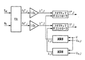
図3に、左右輪の駆動力指令値から左右輪のトルク指令値を生成するスリップ率制御器(SRC)のブロック図を示す。上位のヨーレート制御系から与えられた駆動力指令を、低μ路のドライビングスティフネスを用いてスリップ率の指令値に換算し、下位のスリップ率制御系に与えることでより正確な駆動力配分を実現する。 FIG. 3 is a block diagram of a slip ratio controller (SRC) that generates torque command values for left and right wheels from drive force command values for left and right wheels. The driving force command given from the upper yaw rate control system is converted into the slip ratio command value using the driving stiffness of the low μ road, and given to the lower slip ratio control system to achieve more accurate driving force distribution To do.
ただし、λ*はスリップ率指令値、F* dは駆動力指令値、Dsnはドライビングスティフネスノミナル値である。ドライビングスティフネスは、予め推定した値を用いても、リアルタイムに同定したオンライン値を用いてもよく、オンライン値を用いた場合は路面変化に対応したより正確な駆動力制御が可能となる。スリップ率指令値が過大となる場合は、適当な値でスリップ率指令値にリミッタを設ける。図4に、本発明の一実施形態に係るYMOを用いた走行安定化制御器にSRCを組み込んだスリップ率制御に基づくヨーレート制御ブロック図を示す。これによりヨーレート制御性能は抑制されるものの車輪の空転による車体のヨー軸回りのスピンを防ぐことができる。尚、図3、4には、車体速度からスリップ率を算出するスリップ率制御器のブロック図を示したが、本発明において用いるスリップ率制御としては、これに替えて車体速度検出不要なスリップ率推定に基づくスリップ率制御器(非特許文献7参照)としてもよい。 However, λ * is a slip ratio command value, F * d is a driving force command value, and D sn is a driving stiffness nominal value. The driving stiffness may be a pre-estimated value or an online value identified in real time. When the online value is used, more accurate driving force control corresponding to a road surface change is possible. When the slip ratio command value becomes excessive, a limiter is provided for the slip ratio command value with an appropriate value. FIG. 4 shows a yaw rate control block diagram based on slip ratio control in which SRC is incorporated in a travel stabilization controller using YMO according to an embodiment of the present invention. Thereby, although the yaw rate control performance is suppressed, spin around the yaw axis of the vehicle body due to idling of the wheel can be prevented. 3 and 4 are block diagrams of the slip ratio controller for calculating the slip ratio from the vehicle speed, but the slip ratio control used in the present invention is replaced with a slip ratio that does not require the vehicle speed detection. It is good also as a slip ratio controller based on estimation (refer nonpatent literature 7).
2.1スリップ率制御
2.1.1スリップ率推定
モータのトルク応答の時定数が非常に小さいと仮定するとき、車両の運動方程式は以下の式で表現できる。
2.1 Slip Rate Control 2.1.1 Slip Rate Estimation When it is assumed that the time constant of the motor torque response is very small, the equation of motion of the vehicle can be expressed by the following equation.
各変数は、モータの回転角速度ω、車体速度V、車輪速度Vω、モータトルクT、駆動力Fd、走行抵抗Fdrとする。各定数は、車体質量M、タイヤ半径r、車輪回転慣性モーメントJωとする。またスリップ率λは下記の式(13)で表されるが、本発明では駆動時のみ考えるものとしmax(Vω、V)=Vωとする。 The variables are the rotational angular speed ω of the motor, the vehicle body speed V, the wheel speed V ω , the motor torque T, the driving force F d , and the running resistance F dr . The constants are a vehicle body mass M, a tire radius r, and a wheel rotation inertia moment Jω . The slip ratio λ is expressed by the following formula (13). In the present invention, the slip ratio λ is considered only during driving, and max (V ω , V) = V ω .
この式(13)を両辺時間微分し、式(10)から(12)を式(13)に代入し、Vω、V、Fdを消去すると以下の式(14)を得ることが出来る。 The following equation (14) can be obtained by differentiating this equation (13) with respect to both sides, substituting equations (10) to (12) into equation (13), and eliminating V ω , V, and F d .
ただし、J(λ)は車輪と車体を合わせた回転部分の実際の慣性モーメントである。この式に基づいた以下のスリップ率推定器が提案されている(非特許文献7参照)。 However, J (λ) is the actual moment of inertia of the rotating part combining the wheel and the vehicle body. The following slip ratio estimators based on this equation have been proposed (see Non-Patent Document 7).
センサから得た車輪速度ωと推定して得られたスリップ率 Slip rate obtained by estimating the wheel speed ω obtained from the sensor
(λhut)から車体速度の推定値を得ることが出来る。そして車体速度と目標スリップ率から目標車輪速度ω*を計算することが出来る。 An estimated value of the vehicle body speed can be obtained from (λhut). The target wheel speed ω * can be calculated from the vehicle body speed and the target slip ratio.
これより、一般的に使用されているモータの電流制御ループの外側に速度ループを組んだ回転速度制御を用いることで、スリップ率制御を実現する。 Thus, slip ratio control is realized by using rotational speed control in which a speed loop is formed outside a current control loop of a motor that is generally used.
制御器はPI制御器を用いる。一般的に速度ループは車輪の慣性モーメントを用いて以下の式に基づいて極配置法により制御ゲインを決定する。 The controller uses a PI controller. In general, the speed loop determines the control gain by the pole placement method based on the following equation using the moment of inertia of the wheel.
しかし式(14)より車体全体の慣性モーメントはスリップ率に応じて変化するため車輪の慣性モーメントのみで制御器を設計すると、スリップ率の変化に応じて相対的に制御器の極が変化する。そこで式(14)のJ(λ)=Jω+r2M(1−λ)に対して極が一定になるように制御ゲインをオンラインチューニングする。 However, from equation (14), the inertia moment of the entire vehicle body changes according to the slip ratio. Therefore, when the controller is designed only with the inertia moment of the wheel, the pole of the controller relatively changes according to the change of the slip ratio. Therefore, the control gain is on-line tuned so that the pole becomes constant with respect to J (λ) = Jω + r 2 M (1−λ) in equation (14).
ここでは、スリップ率制御として一例を挙げたが、スリップ率制御であればこれに替えて他のスリップ率制御を用いてもよい。 Here, an example is given as the slip ratio control. However, if the slip ratio control is used, another slip ratio control may be used instead.
3.シミュレーション
低μ路において加速旋回する際のコンピュータシミュレーションを行った。車両モデルは車体質量480kg、ヨー慣性モーメント351Nms2、ホイールベース1.71m、トレッド0.815mである。時速16km/hで走行中に舵角を180deg(実舵角5.83degに相当)切って加速旋回する。駆動トルクは140Nm(片輪70Nm)とし、カットオフ周波数10rad/sのYMOを用いたヨーレート制御を行う。ヨーレート制御器はノミナルプラント1Insに対して閉ループ極を−5rad/sに配置した比例制御とした。スリップ率制御の極は−20rad/sとし、式(9)で使用するドライビングスティフネスはシミュレータ内の低μ路における値である4500とした。
3. Simulation A computer simulation was performed for accelerated turning on a low μ road. The vehicle model has a vehicle body mass of 480 kg, a yaw moment of inertia 351 Nms2, a wheelbase of 1.71 m, and a tread of 0.815 m. During traveling at a speed of 16 km / h, the steering angle is turned 180 deg (corresponding to an actual steering angle of 5.83 deg) and the vehicle turns at an accelerated speed. The drive torque is 140 Nm (single wheel 70 Nm), and yaw rate control using YMO with a cutoff frequency of 10 rad / s is performed. The yaw rate controller is a proportional control in which the closed loop pole is arranged at −5 rad / s with respect to the nominal plant 1Ins. The pole of the slip ratio control was −20 rad / s, and the driving stiffness used in the equation (9) was 4500, which is a value on a low μ road in the simulator.
なお本実施形態の車両シミュレータでは、2次元タイヤモデル/発生力計算プログラム2D−TireModel ver1.0を使用している(非特許文献8)。 In the vehicle simulator of this embodiment, a two-dimensional tire model / generated force calculation program 2D-TireModel ver1.0 is used (Non-Patent Document 8).
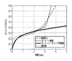
図5に、本発明の一実施形態に係るスリップ率制御に基づくヨーレート制御およびヨーレート制御のみの各場合と、制御なしの場合における車両の走行軌跡を示す。非制御時は旋回を始めると、ヨーモーメントによる姿勢制御が行われないため車体は外側に流れ、特に後輪駆動であるため後輪のコーナリングフォースが著しく減少しスピンし始めている。従来のヨーレート制御のみを行った場合でも、車体のスピンを抑える方向にヨーモーメントを発生させるため左右のモータに逆符号の過大なトルク指令が与えられ、両輪に大空転が発生しスピンに至っている。図6に、本発明の一実施形態に係るスリップ率制御に基づくヨーレート制御およびヨーレート制御のみの各場合の左右輪のスリップ率を示す。この図6からもスピンを抑える方向に駆動力を発生させて空転している様子が分かる。本発明に係るヨーレート制御にスリップ率制御を加えた場合では、スピンすることなく安定して旋回できている。図7に、本発明の一実施形態に係るスリップ率制御に基づくヨーレート制御およびヨーレート制御のみの各場合と、制御なしの場合と、ヨーレート指令値を示す。スリップ率制御に基づくヨーレート制御では、スリップ率を抑えることで車輪のコーナリングフォースで旋回できており、不足分をヨーモーメントで補うことで乾燥路と同等の旋回性能を得られている。 FIG. 5 shows a vehicle trajectory in each case of only yaw rate control and yaw rate control based on slip ratio control according to an embodiment of the present invention, and in the case of no control. When turning is started when the vehicle is not controlled, the vehicle body flows to the outside because posture control by the yaw moment is not performed. Especially, since the vehicle is driven by the rear wheels, the cornering force of the rear wheels is remarkably reduced and starts spinning. Even when only conventional yaw rate control is performed, excessive torque commands with opposite signs are given to the left and right motors in order to generate a yaw moment in a direction that suppresses the spin of the vehicle body, causing both wheels to run large and cause spin. . FIG. 6 shows the slip ratios of the left and right wheels in each case of only the yaw rate control and the yaw rate control based on the slip ratio control according to the embodiment of the present invention. It can be seen from FIG. 6 that the driving force is generated in the direction of suppressing the spin and the wheel is idling. When slip rate control is added to the yaw rate control according to the present invention, the vehicle can stably turn without spinning. FIG. 7 shows yaw rate control and yaw rate control based on slip rate control according to an embodiment of the present invention, no control, and yaw rate command values. In the yaw rate control based on the slip ratio control, the cornering force of the wheel can be turned by suppressing the slip ratio, and the turning performance equivalent to that of the dry road can be obtained by compensating the shortage with the yaw moment.
4.実験結果
小型の電気自動車を用いて走行実験を行った。実験環境は、アルミ製の板を並べて散水することでつくった低μ路面とした。実験条件はシミュレーションと同様とするが、スリップ率制御の極は−50rad/sとした。式(9)で使用するドライビングスティフネスは、実験環境において測定したスリップ率と駆動力オブザーバ(非特許文献9参照)から得た駆動力から約4000と求めた。なお、実験では簡単のため車体速度は推定値ではなくセンサより得た値を使用して制御を行っている。図8に、本発明の一実施形態に係るスリップ率制御に基づくヨーレート制御およびヨーレート制御のみの各場合と、制御なしの場合のヨーレート応答とヨーレート指令値を示す。ヨーレート指令値は乾燥路を同程度の車体速度、操舵角で走行した時のヨーレート応答を基に0.4rad/sとした。非制御の場合では後輪が空転しスピンしている。ヨーレート制御のみの場合でも初期は姿勢を維持しようとするが、ヨーモーメント発生のための駆動力により後輪が空転しスピンしている。ヨーレート制御にスリップ率制御を組み合わせた場合ではそのような空転によるスピンを回避し、乾燥路と同等な旋回が行えている。
4). Experimental results A driving experiment was conducted using a small electric vehicle. The experimental environment was a low-μ road surface made by sprinkling aluminum plates side by side. The experimental conditions are the same as in the simulation, but the pole of slip ratio control is -50 rad / s. The driving stiffness used in Equation (9) was found to be about 4000 from the slip ratio measured in the experimental environment and the driving force obtained from the driving force observer (see Non-Patent Document 9). For the sake of simplicity in the experiment, the vehicle speed is controlled using a value obtained from a sensor, not an estimated value. FIG. 8 shows yaw rate responses and yaw rate command values in the cases of only yaw rate control and yaw rate control based on slip rate control according to an embodiment of the present invention, and in the case of no control. The yaw rate command value was set to 0.4 rad / s based on the yaw rate response when the vehicle traveled on the dry road at the same vehicle speed and steering angle. In the case of non-control, the rear wheel is idle and spinning. Even in the case of only yaw rate control, the posture is initially maintained, but the rear wheel is idled and spun by the driving force for generating the yaw moment. When the slip rate control is combined with the yaw rate control, the spin caused by such idling is avoided, and the same turning as that of the dry road can be performed.
図9に、本発明の一実施形態に係るスリップ率制御に基づくヨーレート制御およびヨーレート制御のみの各場合における左輪のスリップ率応答を示す。ヨーレート制御のみではスリップ率が増大し空転してしまうが、スリップ率制御を組み合わせることで、適切な値に抑えられている。 FIG. 9 shows the slip ratio response of the left wheel in each case of only the yaw rate control and the yaw rate control based on the slip ratio control according to the embodiment of the present invention. Only the yaw rate control increases the slip ratio and causes idling, but it is suppressed to an appropriate value by combining the slip ratio control.
図10に、本発明の一実施形態に係るスリップ率制御に基づくヨーレート制御およびヨーレート制御のみの各場合と、制御なしの場合における横加速度応答を示す。非制御の場合では横加速度の絶対値が増大し車体が横滑りしていることが分かる。ヨーレート制御のみ行う場合ではヨーレート応答の改善に従い、横加速度応答も比較的改善されるが、スリップ率制御を組み合わせることにより更に改善されることが分かる。 FIG. 10 shows lateral acceleration response in each case of only yaw rate control and yaw rate control based on slip ratio control according to an embodiment of the present invention and in the case of no control. In the case of non-control, it can be seen that the absolute value of the lateral acceleration increases and the vehicle body skids. When only the yaw rate control is performed, the lateral acceleration response is relatively improved as the yaw rate response is improved. However, it can be seen that the improvement is further improved by combining the slip rate control.
以上のことから、スリップ率制御に基づいたヨーレート制御の優位性を低μ路において示す事ができた。現在定数としてスリップ率制御に用いているドライビングスティフネスをオンラインで推定し、その値を用いてスリップ率制御を行うことが出来れば、路面変動などに対し、より正確なヨーレート制御の実現が期待できる。 From the above, the superiority of the yaw rate control based on the slip ratio control could be shown in the low μ road. If the driving stiffness used for slip rate control as a current constant is estimated online and the slip rate control can be performed using the estimated value, it is possible to realize more accurate yaw rate control for road surface fluctuations and the like.
5.ドライビングスティフネス推定
前章で述べたように、路面の粘着状態を示す重要なパラメータであり時々刻々と変化するドライビングスティフネスを、定数からリアルタイムに推定しスリップ率制御に用いることにより、路面変化に対してよりロバストなスリップ率制御を行うことができる。以下でドライビングスティフネスの推定法と、路面状態が変化した時の効果をシミュレーションにより示す。
5). Driving stiffness estimation As mentioned in the previous chapter, the driving stiffness, which is an important parameter that indicates the adhesion state of the road surface and that changes from moment to moment, is estimated in real time from a constant value and used for slip ratio control. Robust slip ratio control can be performed. Below, the estimation method of driving stiffness and the effect when the road surface condition changes are shown by simulation.
5.1左右輪独立推定法
まず左右各輪のドライビングスティフネスを独立に推定する方法について述べる。車両の前後並進方向の運動方程式は以下のように表される。
5.1 Independent estimation method for left and right wheels First, a method for independently estimating the driving stiffness of the left and right wheels will be described. The equation of motion in the longitudinal translation direction of the vehicle is expressed as follows.
ただし、Mは車体質量、Vdotは車体加速度、DsR、DsLは左右駆動輪と路面間のドライビングスティフネス、λR、λLは左右駆動輪のスリップ率である。これを変形して次式を得る。 Where M is the vehicle body mass, Vdot is the vehicle body acceleration, D sR and D sL are the driving stiffness between the left and right drive wheels and the road surface, and λ R and λ L are the slip ratios of the left and right drive wheels. This is transformed to obtain the following formula.
上式のリグレッサ[ξ1、ξ2]と出力Vdotにより、未知パラメータであるドライビングスティフネス[DsR、DsL]を推定することを考える。リグレッサはスリップ率λを推定あるいは計測することで計算することが出来る。 It is assumed that the driving stiffness [D sR , D sL ], which is an unknown parameter, is estimated from the regressors [ξ 1 , ξ 2 ] and the output Vdot in the above equation. The regressor can be calculated by estimating or measuring the slip ratio λ.
この推定式に忘却係数λを用いた逐次形最小二乗法を用い、次式に基づき推定する。 A recursive least square method using a forgetting factor λ is used for this estimation formula, and estimation is performed based on the following formula.
つぎに簡単のために左右のドライビングスティフネスを等しいものと仮定(DsR=DsL=Ds)とすることにより推定パラメータを1個にする方法について述べる。すなわち式(18)を変形して次式を得る。 Next, for the sake of simplicity, a method of setting one estimation parameter by assuming that the left and right driving stiffnesses are equal (D sR = D sL = D s ) will be described. That is, the following equation is obtained by modifying the equation (18).
この推定式に忘却係数λを用いた逐次型最小二乗法を用いて推定する。 The estimation formula is estimated using a sequential least square method using a forgetting factor λ.
6.3シミュレーション
ドライビングスティフネスのリアルタイム推定を用いたスリップ率制御を用いた、ヨーレート制御のシミュレーションを行った。シミュレーション条件は前章のものと同様とするが、路面の摩擦係数の変化(低μ路(μ=0.25)から高μ路(μ=0.9)へ進入)を伴うものとする。路面の摩擦係数の変化はドライビングスティフネスに大きく影響するため、リアルタイムに路面状態を推定することでより正確なスリップ率制御が期待できる。
6.3 Simulation A simulation of yaw rate control using slip ratio control using real-time estimation of driving stiffness was performed. The simulation conditions are the same as those in the previous chapter, but with a change in the friction coefficient of the road surface (from a low μ road (μ = 0.25) to a high μ road (μ = 0.9)). Since the change in the friction coefficient of the road surface greatly affects the driving stiffness, more accurate slip ratio control can be expected by estimating the road surface state in real time.
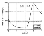
図11に、ドライビングスティフネスに定数値を用いたものと、推定値を用いたものの車両の走行軌跡を示す。推定値を用いることでスリップ率を適切に保つことができるため車輪の空転を防ぎ、より旋回能力を高めていることが分かる。図12に、そのときの本発明の一実施形態に係るスリップ率制御に基づくヨーレート制御において推定されたドライビングスティフネスを示す。高μ路に進入する2secからドライビングスティフネスが大きく増大している様子が分かる。以上からドライビングスティフネス推定値を用いることで路面変動に対してスリップ率制御のロバスト性を高めることが期待できる。 FIG. 11 shows the driving trajectory of a vehicle using a constant value for driving stiffness and an estimated value. It can be seen that the slip rate can be appropriately maintained by using the estimated value, so that the wheel slipping is prevented and the turning ability is further improved. FIG. 12 shows driving stiffness estimated in yaw rate control based on slip rate control according to an embodiment of the present invention at that time. It can be seen that the driving stiffness has greatly increased from 2 seconds entering the high μ road. From the above, it can be expected that the robustness of the slip ratio control is improved against the road surface fluctuation by using the estimated driving stiffness.
また、これまで2輪駆動車を対象として説明してきたが、本発明は4輪駆動車にも適用可能である。例えば、駆動力指令値F* R、F* Lを半分ずつ前後に割振ってスリップ率指令値に変換し、その指令値に基づいて各輪のスリップ率制御を行うようにすればよい。 Further, although the description has been made so far for the two-wheel drive vehicle, the present invention is also applicable to a four-wheel drive vehicle. For example, the driving force command values F * R and F * L may be divided back and forth by half and converted into slip rate command values, and the slip rate control of each wheel may be performed based on the command values.
Claims (12)
所与の舵角から所定のヨーレート指令値を算出するヨーレート演算手段と、
入力されたヨーレートからモーメントを算出するモーメント演算手段と、
外乱を抑圧するヨーレートオブザーバ(YMO)であって、計測されたヨーレートと前記モーメントからヨー軸周りのモーメントである駆動力モーメントを生成するYMOと、
前記駆動力モーメントと前記第1および第2の駆動輪に対する駆動力指令の和であるアクセル指令値とに基づいて第1の駆動輪に対応する第1の駆動力指令値と第2の駆動輪に対応する第2の駆動力指令値を算出するトルク分配演算手段と、
前記第1および第2の各駆動力指令値をそれぞれ第1および第2のスリップ率指令値に変換するトルク・スリップ率変換手段と、
前記第1および第2のスリップ率指令値からスリップ率検出或いは推定に基づいてスリップ率制御された第1および第2のトルク指令値を算出するスリップ率制御手段と
を備え、前記YMOは、タイヤの横力が発生するコーナリングフォースによるモーメント及び横風などによる外乱モーメントを外乱として扱い、前記モータ制御手段は、前記第1のトルク指令値に基づいて前記第1の駆動輪の第1のモータを制御し、前記第2のトルク指令値に基づいて前記第2の駆動輪の第2のモータを制御することを特徴とするスリップ率制御に基づくヨーレート制御装置。 Slip rate control for controlling the yaw rate of an automobile that drives the first and second drive wheels with the first and second motors, respectively, having motor control means for controlling the first and second motors based on a torque command. In the yaw rate control device based on
A yaw rate calculating means for calculating a predetermined yaw rate command value from a given rudder angle;
A moment calculation means for calculating a moment from the input yaw rate;
A yaw rate observer (YMO) that suppresses disturbance, and generates a driving force moment that is a moment around the yaw axis from the measured yaw rate and the moment;
A first driving force command value and a second driving wheel corresponding to the first driving wheel based on the driving force moment and an accelerator command value which is a sum of driving force commands for the first and second driving wheels. Torque distribution calculating means for calculating a second driving force command value corresponding to
Torque / slip ratio converting means for converting the first and second driving force command values into first and second slip ratio command values, respectively;
Slip ratio control means for calculating first and second torque command values that are slip ratio controlled based on slip ratio detection or estimation from the first and second slip ratio command values, wherein the YMO is a tire The moment by the cornering force that generates the lateral force and the disturbance moment by the side wind are treated as disturbances, and the motor control means controls the first motor of the first drive wheel based on the first torque command value. And a yaw rate control device based on slip ratio control, wherein the second motor of the second drive wheel is controlled based on the second torque command value.
所与の舵角から所定のヨーレート指令値を算出するヨーレート演算ステップと、
入力されたヨーレートからモーメントを算出するモーメント演算ステップと、
ヨーレートオブザーバ(YMO)を構成して外乱を抑圧する外乱抑圧ステップであって、計測されたヨーレートと前記モーメントからヨー軸周りのモーメントである駆動力モーメントを生成する外乱抑圧ステップと、
前記駆動力モーメントと前記第1および第2の駆動輪に対する駆動力指令の和であるアクセル指令値とに基づいて前記第1の駆動輪に対応する第1の駆動力指令値と前記第2の駆動輪に対応する第2の駆動力指令値を算出するトルク分配演算ステップと、
前記第1および第2の各駆動力指令値をそれぞれ第1および第2のスリップ率指令値に変換するトルク・スリップ率変換ステップと、
前記第1および第2のスリップ率指令値からスリップ率推定に基づいてスリップ率制御された第1および第2のトルク指令値を算出するスリップ率制御ステップと
を有し、前記外乱抑圧ステップは、タイヤの横力が発生するコーナリングフォースによるモーメント及び横風などによる外乱モーメントを外乱として扱い、前記モータ制御ステップは、前記第1のトルク指令値に基づいて前記第1の駆動輪の第1のモータを制御し、前記第2のトルク指令値に基づいて前記第2の駆動輪の第2のモータを制御することを特徴とするスリップ率制御に基づくヨーレート制御方法。 Slip rate control for controlling the yaw rate of an automobile that drives the first and second drive wheels with the first and second motors, respectively, having a motor control step for controlling the first and second motors based on a torque command. In the yaw rate control step based on
A yaw rate calculation step for calculating a predetermined yaw rate command value from a given rudder angle;
A moment calculation step for calculating a moment from the input yaw rate;
A disturbance suppression step of configuring a yaw rate observer (YMO) to suppress disturbance, and a disturbance suppression step of generating a driving force moment that is a moment around the yaw axis from the measured yaw rate and the moment;
Based on the driving force moment and an accelerator command value that is a sum of driving force commands for the first and second driving wheels, the first driving force command value corresponding to the first driving wheel and the second driving force command value A torque distribution calculation step for calculating a second driving force command value corresponding to the driving wheel;
A torque / slip ratio conversion step for converting the first and second driving force command values into first and second slip ratio command values, respectively;
A slip ratio control step of calculating first and second torque command values that are slip ratio controlled based on slip ratio estimation from the first and second slip ratio command values, and the disturbance suppression step includes: A moment by a cornering force that generates a lateral force of a tire and a disturbance moment by a side wind are treated as disturbances, and the motor control step uses the first motor of the first drive wheel based on the first torque command value. A yaw rate control method based on slip ratio control, comprising: controlling and controlling a second motor of the second drive wheel based on the second torque command value.
所与の舵角から所定のヨーレート指令値を算出するヨーレート演算手段と、
入力されたヨーレートからモーメントを算出するモーメント演算手段と、
外乱を抑圧するヨーレートオブザーバ(YMO)であって、計測されたヨーレートと前記モーメントからヨー軸周りのモーメントである駆動力モーメントを生成するYMOと、
前記駆動力モーメントと前記第1から第4の駆動輪に対する駆動力指令の和であるアクセル指令値とに基づいて第1から第4の駆動輪に対応する第1から第4の駆動力指令値を算出するトルク分配演算手段と、
前記第1から第4の各駆動力指令値をそれぞれ第1から第4のスリップ率指令値に変換するトルク・スリップ率変換手段と、
前記第1から第4のスリップ率指令値からスリップ率検出或いは推定に基づいてスリップ率制御された第1から第4のトルク指令値を算出するスリップ率制御手段と
を備え、前記YMOは、タイヤの横力が発生するコーナリングフォースによるモーメント及び横風などによる外乱モーメントを外乱として扱い、前記モータ制御手段は、前記第1から第4のトルク指令値に基づいて前記第1から第4の駆動輪の第1から第4のモータを制御することを特徴とするスリップ率制御に基づくヨーレート制御装置。 Slip rate control for controlling the yaw rate of an automobile that drives the first to fourth drive wheels with the first to fourth motors, respectively, having motor control means for controlling the first to fourth motors based on a torque command. In the yaw rate control device based on
A yaw rate calculating means for calculating a predetermined yaw rate command value from a given rudder angle;
A moment calculation means for calculating a moment from the input yaw rate;
A yaw rate observer (YMO) that suppresses disturbance, and generates a driving force moment that is a moment around the yaw axis from the measured yaw rate and the moment;
First to fourth driving force command values corresponding to the first to fourth driving wheels based on the driving force moment and an accelerator command value that is a sum of driving force commands for the first to fourth driving wheels. Torque distribution calculating means for calculating
Torque / slip ratio converting means for converting the first to fourth driving force command values into first to fourth slip ratio command values, respectively.
Slip ratio control means for calculating first to fourth torque command values that are slip ratio controlled based on slip ratio detection or estimation from the first to fourth slip ratio command values, wherein the YMO is a tire The moment due to the cornering force that generates the lateral force and the disturbance moment due to the side wind are treated as disturbances, and the motor control means is configured to control the first to fourth driving wheels based on the first to fourth torque command values. A yaw rate control device based on slip ratio control, wherein the first to fourth motors are controlled.
所与の舵角から所定のヨーレート指令値を算出するヨーレート演算ステップと、
入力されたヨーレートからモーメントを算出するモーメント演算ステップと、
ヨーレートオブザーバ(YMO)を構成して外乱を抑圧する外乱抑圧ステップであって、計測されたヨーレートと前記モーメントからヨー軸周りのモーメントである駆動力モーメントを生成する外乱抑圧ステップと、
前記駆動力モーメントと前記第1から第4の駆動輪に対する駆動力指令の和であるアクセル指令値とに基づいて前記第1から第4の駆動輪に対応する第1から第4の駆動力指令値を算出するトルク分配演算ステップと、
前記第1から第4の各駆動力指令値をそれぞれ第1から第4のスリップ率指令値に変換するトルク・スリップ率変換ステップと、
前記第1から第4のスリップ率指令値からスリップ率推定に基づいてスリップ率制御された第1から第4のトルク指令値を算出するスリップ率制御ステップと
を有し、前記外乱抑圧ステップは、タイヤの横力が発生するコーナリングフォースによるモーメント及び横風などによる外乱モーメントを外乱として扱い、前記モータ制御ステップは、前記第1から第4のトルク指令値に基づいて前記第1から第4の駆動輪の第1から第4のモータを制御することを特徴とするスリップ率制御に基づくヨーレート制御方法。 Slip rate control for controlling the yaw rate of an automobile that drives the first to fourth drive wheels with the first to fourth motors, respectively, having motor control steps for controlling the first to fourth motors based on a torque command. In the yaw rate control step based on
A yaw rate calculation step for calculating a predetermined yaw rate command value from a given rudder angle;
A moment calculation step for calculating a moment from the input yaw rate;
A disturbance suppression step of configuring a yaw rate observer (YMO) to suppress disturbance, and a disturbance suppression step of generating a driving force moment that is a moment around the yaw axis from the measured yaw rate and the moment;
First to fourth driving force commands corresponding to the first to fourth driving wheels based on the driving force moment and an accelerator command value that is the sum of the driving force commands for the first to fourth driving wheels. A torque distribution calculation step for calculating a value;
A torque / slip ratio conversion step for converting the first to fourth driving force command values into first to fourth slip ratio command values, respectively;
A slip ratio control step of calculating first to fourth torque command values that are slip ratio controlled based on slip ratio estimation from the first to fourth slip ratio command values, and the disturbance suppression step includes: A moment caused by a cornering force that generates a lateral force of a tire and a disturbance moment caused by a side wind or the like are treated as disturbances, and the motor control step includes the first to fourth drive wheels based on the first to fourth torque command values. A yaw rate control method based on slip ratio control, wherein the first to fourth motors are controlled.
Priority Applications (1)
| Application Number | Priority Date | Filing Date | Title |
|---|---|---|---|
| JP2007213185A JP4925455B2 (en) | 2007-08-17 | 2007-08-17 | Yaw rate control device and control method |
Applications Claiming Priority (1)
| Application Number | Priority Date | Filing Date | Title |
|---|---|---|---|
| JP2007213185A JP4925455B2 (en) | 2007-08-17 | 2007-08-17 | Yaw rate control device and control method |
Publications (2)
| Publication Number | Publication Date |
|---|---|
| JP2009050077A true JP2009050077A (en) | 2009-03-05 |
| JP4925455B2 JP4925455B2 (en) | 2012-04-25 |
Family
ID=40501767
Family Applications (1)
| Application Number | Title | Priority Date | Filing Date |
|---|---|---|---|
| JP2007213185A Expired - Fee Related JP4925455B2 (en) | 2007-08-17 | 2007-08-17 | Yaw rate control device and control method |
Country Status (1)
| Country | Link |
|---|---|
| JP (1) | JP4925455B2 (en) |
Cited By (3)
| Publication number | Priority date | Publication date | Assignee | Title |
|---|---|---|---|---|
| JP2016040968A (en) * | 2014-08-12 | 2016-03-24 | マツダ株式会社 | Electric vehicle slip ratio control device |
| JP2017046494A (en) * | 2015-08-27 | 2017-03-02 | 富士重工業株式会社 | Control device of vehicle and control method of vehicle |
| JP2017184615A (en) * | 2017-06-15 | 2017-10-05 | 株式会社Subaru | Vehicle control device and vehicle control method |
Citations (9)
| Publication number | Priority date | Publication date | Assignee | Title |
|---|---|---|---|---|
| JPH0781609A (en) * | 1993-09-09 | 1995-03-28 | Nissan Motor Co Ltd | Vehicle automatic travel control device |
| JP2003159966A (en) * | 2001-11-27 | 2003-06-03 | Toyota Motor Corp | Vehicle running control device |
| JP2003175749A (en) * | 2001-12-12 | 2003-06-24 | Toyota Motor Corp | Vehicle running control device |
| JP2005088726A (en) * | 2003-09-17 | 2005-04-07 | Advics:Kk | Tire pressure alarm device, tire monitored by this device, and method for managing tire characteristic values |
| JP2005160262A (en) * | 2003-11-28 | 2005-06-16 | Toyota Motor Corp | Vehicle driving force control device |
| JP2006034012A (en) * | 2004-07-16 | 2006-02-02 | Toyota Motor Corp | Wheel slip ratio calculation method and wheel braking / driving force control method |
| JP2007104892A (en) * | 2005-09-06 | 2007-04-19 | Nissan Motor Co Ltd | Vehicle slip control device |
| JP2007176260A (en) * | 2005-12-27 | 2007-07-12 | Hitachi Ltd | Brake control device and control method |
| WO2008029524A1 (en) * | 2006-09-07 | 2008-03-13 | Yokohama National University | Slip ratio estimating device and slip ratio control device |
-
2007
- 2007-08-17 JP JP2007213185A patent/JP4925455B2/en not_active Expired - Fee Related
Patent Citations (9)
| Publication number | Priority date | Publication date | Assignee | Title |
|---|---|---|---|---|
| JPH0781609A (en) * | 1993-09-09 | 1995-03-28 | Nissan Motor Co Ltd | Vehicle automatic travel control device |
| JP2003159966A (en) * | 2001-11-27 | 2003-06-03 | Toyota Motor Corp | Vehicle running control device |
| JP2003175749A (en) * | 2001-12-12 | 2003-06-24 | Toyota Motor Corp | Vehicle running control device |
| JP2005088726A (en) * | 2003-09-17 | 2005-04-07 | Advics:Kk | Tire pressure alarm device, tire monitored by this device, and method for managing tire characteristic values |
| JP2005160262A (en) * | 2003-11-28 | 2005-06-16 | Toyota Motor Corp | Vehicle driving force control device |
| JP2006034012A (en) * | 2004-07-16 | 2006-02-02 | Toyota Motor Corp | Wheel slip ratio calculation method and wheel braking / driving force control method |
| JP2007104892A (en) * | 2005-09-06 | 2007-04-19 | Nissan Motor Co Ltd | Vehicle slip control device |
| JP2007176260A (en) * | 2005-12-27 | 2007-07-12 | Hitachi Ltd | Brake control device and control method |
| WO2008029524A1 (en) * | 2006-09-07 | 2008-03-13 | Yokohama National University | Slip ratio estimating device and slip ratio control device |
Cited By (3)
| Publication number | Priority date | Publication date | Assignee | Title |
|---|---|---|---|---|
| JP2016040968A (en) * | 2014-08-12 | 2016-03-24 | マツダ株式会社 | Electric vehicle slip ratio control device |
| JP2017046494A (en) * | 2015-08-27 | 2017-03-02 | 富士重工業株式会社 | Control device of vehicle and control method of vehicle |
| JP2017184615A (en) * | 2017-06-15 | 2017-10-05 | 株式会社Subaru | Vehicle control device and vehicle control method |
Also Published As
| Publication number | Publication date |
|---|---|
| JP4925455B2 (en) | 2012-04-25 |
Similar Documents
| Publication | Publication Date | Title |
|---|---|---|
| JP4538642B2 (en) | Slip rate estimation device and slip rate control device | |
| CN109747434B (en) | Distributed driving electric vehicle torque vector distribution control method | |
| Sakai et al. | Motion control in an electric vehicle with four independently driven in-wheel motors | |
| Hori et al. | Traction control of electric vehicle: basic experimental results using the test EV" UOT electric march" | |
| JP6333917B2 (en) | Vehicle turning control device | |
| CN104245408B (en) | Electric-vehicle control device, and method for controlling electric vehicle | |
| CN109070763B (en) | Electric vehicle control method and electric vehicle control device | |
| JP6440971B2 (en) | Drive control device with traction control function for left and right independent drive vehicles | |
| CN113733929A (en) | Wheel torque coordination control method and device for wheel hub motor driven vehicle | |
| Sakai et al. | Dynamic driving/braking force distribution in electric vehicles with independently driven four wheels | |
| CN107848526A (en) | Turn inside diameter control device | |
| JP2017093003A (en) | Slip control device | |
| Kim et al. | Model predictive control for energy-efficient yaw-stabilizing torque vectoring in electric vehicles with four in-wheel motors | |
| KR20150062779A (en) | Enhancement of cornering stability of direct-drive electric vehicle | |
| JP6664885B2 (en) | Vehicle braking / driving torque control device | |
| Fujimoto et al. | Optimal yaw-rate control for electric vehicles with active front-rear steering and four-wheel driving-braking force distribution | |
| CN107179686A (en) | A kind of distributed-driving electric automobile lateral stability high-order variable structure control method based on gray prediction | |
| Zhang et al. | Novel electronic braking system design for EVS based on constrained nonlinear hierarchical control | |
| JP6267440B2 (en) | Vehicle control device | |
| JP4925455B2 (en) | Yaw rate control device and control method | |
| Vasiljevic et al. | Slip-based traction control system with an on-line road condition estimation for electric vehicles | |
| Mashadi et al. | Integrated AFS/DYC sliding mode controller for a hybrid electric vehicle | |
| JP2010076739A (en) | Apparatus and method for controlling vehicle attitude for automobile | |
| Fujimoto et al. | Advanced motion control of electric vehicle based on lateral force observer with active steering | |
| Wang et al. | A robust control method for lateral stability control of in‐wheel motored electric vehicle based on sideslip angle observer |
Legal Events
| Date | Code | Title | Description |
|---|---|---|---|
| A621 | Written request for application examination |
Free format text: JAPANESE INTERMEDIATE CODE: A621 Effective date: 20100524 |
|
| A977 | Report on retrieval |
Free format text: JAPANESE INTERMEDIATE CODE: A971007 Effective date: 20110805 |
|
| TRDD | Decision of grant or rejection written | ||
| A01 | Written decision to grant a patent or to grant a registration (utility model) |
Free format text: JAPANESE INTERMEDIATE CODE: A01 Effective date: 20120106 |
|
| A01 | Written decision to grant a patent or to grant a registration (utility model) |
Free format text: JAPANESE INTERMEDIATE CODE: A01 |
|
| A61 | First payment of annual fees (during grant procedure) |
Free format text: JAPANESE INTERMEDIATE CODE: A61 Effective date: 20120206 |
|
| FPAY | Renewal fee payment (event date is renewal date of database) |
Free format text: PAYMENT UNTIL: 20150217 Year of fee payment: 3 |
|
| R150 | Certificate of patent or registration of utility model |
Free format text: JAPANESE INTERMEDIATE CODE: R150 |
|
| R250 | Receipt of annual fees |
Free format text: JAPANESE INTERMEDIATE CODE: R250 |
|
| LAPS | Cancellation because of no payment of annual fees | ||
| S531 | Written request for registration of change of domicile |
Free format text: JAPANESE INTERMEDIATE CODE: R313531 |
|
| R350 | Written notification of registration of transfer |
Free format text: JAPANESE INTERMEDIATE CODE: R350 |